
Related Manuals for Azbil VDC


Summary of Contents for Azbil VDC
- Page 1 Diaphragm Control Valve Model: VDC, VAC, VST,VAA ANSI Class 600 or under User’s Manual OM2-8110-0300 13th edition...
- Page 2 In no event is Azbil Corporation liable to anyone for any indirect, special or consequential damages. This information and specifi- cations in this document are subject to change without notice.
-
Page 3: Safety Guide
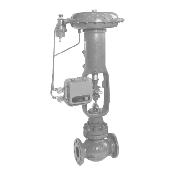
Safety Guide 1 : Nomenclature of parts Diagrams with the control valve terminologies and words used in this manual are shown below. Please familiarise yourself with these definitions before using the device. Diaphragm Actuator Yoke Bonnet Flange Valve body Figure S-1 Nomenclature of globe valve Actuator Body Link... -
Page 4: Safety Precautions
Safety Guide Azbil Corporation 2 : Safety precautions Please read this section before using the valve to ensure proper handling. WARNING If the stated procedures are not followed as specified, a potentially hazardous situation may arise, which could result in death or serious injury. - Page 5 Azbil Corporation Safety Guide Compliance with Regulations This product complies with the directive below. • Pressure Equipment Directive (PED) 2014/63/EU Requirements for workers (installation, operation, maintenance) To ensure safety, only specialists who are skilled in instrumentation work should carry out the installation, operation, and maintenance of this device.
-
Page 6: Installation
Safety Guide Azbil Corporation 4 : Installation 4-1 : Installation environments CAUTION • Ensure sufficient space for easy and Maintenance space safe operation and maintenance of the control valve. • Avoid installing the valve in a location where vibration or external stress may impair proper valve functions. - Page 7 Azbil Corporation Safety Guide Prior to installation work, follow the items of caution as described below: CAUTION • Check and confirm that there is no external damage to the valve (body, actuator, accessories). • Check and confirm that there is no damage on pipe connecting flanges or butt welding connections.
- Page 8 Safety Guide Azbil Corporation 4-2 : Installation work CAUTION • Ensure that centers of upstream and downstream pipes are aligned when pipe installation has been completed. Any mis-alignment of pipe will distort the valve and will cause leakage from the connections. (Gasket) •...
- Page 9 Azbil Corporation Safety Guide 4-3 : Pneumatic piping and electric work CATUTION • Pneumatic tubing should be sized so as not to cause dropping of air pressure when the control valve is in operation. Pneumatic tubing should have an allowance in bend (use specialized tool) and the parallel tubing should be clamped together.
-
Page 10: Caution On Disassembly And Reassembly
Safety Guide Azbil Corporation 5 : Caution on disassembly and reassembly 5-1 : Disassembly CATUTION Eye bolt Spring • When disassembling a spring- incorporated positioner, follow the prescribed procedure in removing bolts and nuts. Otherwise, the spring may pop out and could resulting in physical injury. -
Page 11: Assembly
Azbil Corporation Safety Guide 6 : Assembly CATUTION Follow assembly procedure • When assembling the spring loaded actuator, adhere to the order of assembly procedure; install bolts and nuts as instructed. Disregard of procedure may result in malfunction. • When installing a butterfly valve on a pipe line, fully close the valve (vane or disk). -
Page 12: Maintenance And Inspection
Safety Guide Azbil Corporation 7 : Maintenance and inspection Adhere to the following warnings and cautions while conducting maintenance or inspection. CAUTION If there is leakage from a valve, do not come close to the valve until safety is assured of. -
Page 13: Table Of Contents
6-1 : Replacement of Gland Packing ..............6-1 6-2 : Replacement of valve plug and Cage of VDC or VAC Control valve... 6-3 6-3 : Replacement of valve plug and seat ring of VST, VAA, or VAV Control Valve ... 6-4 6-4 : Diaphragm Replacement of Diaphragm Motor (See Figure 1-6, 1-7.) .. - Page 14 7-1 : Operation Method ..................7-1 7-2 : Installation ....................7-1 7-3 : Disassembly and Reassembly ..............7-1 Chapter 8 : Trouble shooting Chapter 9 : Recommended Spare parts 9-1 : Major replacement parts ................9-1 VDC, VAC, VST, VAA - Diaphragm Control Valve...
-
Page 15: Chapter 1 : General
Chapter 1 : General This manual covers the instruction for the Cage type Double Seated Control Valves (Model VDC), Cage type Angles (Model VAC), Top Guiding SIngle Seated Control Valves (Model VST) and Acorn type, Angle Control Valves (Model VAA). Model: VDC... -
Page 16: Specification Of Control Valves
(See Figure. 1-6, 1-7.) ~Note “Air- O-Motor” is Azbil Corporation's trade name for its diaphragm motors (Models VA1 to 5). VDC, VAC, VST, VAA - Diaphragm Control Valve... - Page 17 Azbil Corporation General Figure 1-2 Model: VDC Cage type Double Seated Control Valve (Rating: ANSI 600 lb. or less) Item no. Parts Item no. Parts Valve stem V Packing retainer Stud bolt V Packing spring Blind plug Packing flange Packing ring...
- Page 18 Blind plug Packing flange Packing ring Yoke nut Stud bolt Bonnet Gasket Gasket Valve plug Valve body Cage Drain plug Packing follower Lubricator V Packing Holder Latern ring V PTFE packing Packing VDC, VAC, VST, VAA - Diaphragm Control Valve...
- Page 19 Yoke nut Bonnet Valve plug Seat ring Guide bushing Valve body Gasket Drain plug Guide ring Lubricator Packing follower Lantern ring V packing holder Packing V PTFE packing Guide V packing retainer VDC, VAC, VST, VAA - Diaphragm Control Valve...
- Page 20 Yoke nut Bonnet Valve plug Seat ring Guide bushing Valve body Gasket Drain plug Guide ring Lubricator Packing follower Lantern ring V packing holder Packing V PTFE packing Guide V packing retainer VDC, VAC, VST, VAA - Diaphragm Control Valve...
- Page 21 Azbil Corporation General Figure 1-6 VDC, VAC, VST, VAA - Diaphragm Control Valve...
- Page 22 General Azbil Corporation Figure 1-7 Actuators (Air-0-Motor) VDC, VAC, VST, VAA - Diaphragm Control Valve...
-
Page 23: Chapter 2 : Installation Of A Control Valve
For details, see Chapter 5. “Disassembly and Reassembly of a Control Valve.” VDC, VAC, VST, VAA - Diaphragm Control Valve... - Page 24 Installation of a Control Valve Azbil Corporation VDC, VAC, VST, VAA - Diaphragm Control Valve...
-
Page 25: Chapter 3 : Inspection And Maintenance Of Control Valves
Check that there is no process fluid leak from the bonnet and flanges. • Check that the yoke clamp bolt is not loose. • Check that there is no air leak from the air piping of the actuator. VDC, VAC, VST, VAA - Diaphragm Control Valve... -
Page 26: Lubrication Of Gland Packing (For Valve With Asbestos Packing) (See Figure.3-1)
Be sure to securely tighten the lubricator handwheel when the lubrication work is finished. It is recommended to tighten slightly more the packing flange bolt slightly more after lubrication work is finished. Figure 3-1 Lubricator VDC, VAC, VST, VAA - Diaphragm Control Valve... -
Page 27: Chapter 4 : Control Valve Adjustment
Reduce the air pressure to the diaphragm chamber and verify if the valve lift is more than the rated lift range (min. 1 mm) and the valve seat and plug touch each other. Make sure that this contact takes place while in the SHUT position. VDC, VAC, VST, VAA - Diaphragm Control Valve... -
Page 28: Spring Compression Adjustment
Make this adjustment after both lift adjustment and spring tightening adjustment have been completed. CM2-AVP300-2001 Single acting electro/pneumatic valve positioner: Model: AVP300, 301 OM2-8310-0200 Single acting electro/pneumatic positioner: Model HTP OM2-8313-0100 Single acting electro/pneumatic valve positioner: Model HEP15, 16, 17 VDC, VAC, VST, VAA - Diaphragm Control Valve... - Page 29 Azbil Corporation Control Valve Adjustment Figure 4-1 Actuator (Reverse acting type) VDC, VAC, VST, VAA - Diaphragm Control Valve...
- Page 30 Control Valve Adjustment Azbil Corporation VDC, VAC, VST, VAA - Diaphragm Control Valve...
-
Page 31: Chapter 5 : Disassembly And Reassembly
Next, set the valve plug on the seat ring to which the valve stem has been assembled. Place gasket (lower), guide ring, and gasket (upper) in the due order. (2) For Model VDC or VAC valve, insert the spiral gasket at first. (Do not reuse the removed gasket. Always use a fresh gasket.) Next, place gasket (lower), cage, and gasket (upper) in the due order. -
Page 32: Disassembly And Reassembly Of Bellows-Sealed Valve
Make sure to hold the bellows seat with a wrench when tightening the hex nut of the bellows flange, lest unreasonably large force should not be applied to the bellows. VDC, VAC, VST, VAA - Diaphragm Control Valve... - Page 33 Azbil Corporation Disassembly and Reassembly Figure 5-1 Cross section of Control Valve (Model: VST for example) VDC, VAC, VST, VAA - Diaphragm Control Valve...
- Page 34 Disassembly and Reassembly Azbil Corporation Figure 5-2 Cross Section of Valve Body of Model VDC (unit-structure cage type) Figure 5-3 Cross Section of Valve Body of Model VDC (split cage type) VDC, VAC, VST, VAA - Diaphragm Control Valve...
- Page 35 Azbil Corporation Disassembly and Reassembly Figure 5-4 Cross section of bellows seal bonnet VDC, VAC, VST, VAA - Diaphragm Control Valve...
- Page 36 Disassembly and Reassembly Azbil Corporation VDC, VAC, VST, VAA - Diaphragm Control Valve...
-
Page 37: Chapter 6 : Parts Replacement
For reassembly of valve after packing replacement, follow the procedure explained in Chapter 4. “Disassembly and Reassembly“, Item (b) “Assembly,” Steps (5) and further. VDC, VAC, VST, VAA - Diaphragm Control Valve... - Page 38 Parts Replacement Azbil Corporation Figure 6-1 Yarn Packing Figure 6-2 “V“PTFE Packing VDC, VAC, VST, VAA - Diaphragm Control Valve...
-
Page 39: Replacement Of Valve Plug And Cage Of Vdc Or Vac Control Valve
Figure 6-3 Yarn and “V“PTFE, Combined Packing 6-2 : Replacement of valve plug and Cage of VDC or VAC Control valve. To replace the valve plug and cage of Model VDC or VAC control valve, follow the procedure explained in Chapter 4. “Disassembly and Reassembly“. -
Page 40: Replacement Of Valve Plug And Seat Ring Of Vst, Vaa, Or Vav Control Valve
Unite the valve seat at this stage so that the valve plug, gasket (lower) and guide ring are assembled together. Figure 6-6 VST Valve Body and Trim VDC, VAC, VST, VAA - Diaphragm Control Valve... -
Page 41: Diaphragm Replacement Of Diaphragm Motor (See Figure 1-6, 1-7.)
After replacing the diaphragm, assemble the actuator following the above procedure in the reverse order. Disconnect air connection. Remove hex clamp bolts of the diaphragm case assembly and then remove diaphragm case (upper). VDC, VAC, VST, VAA - Diaphragm Control Valve... -
Page 42: O-Ring Replacement Of Diaphragm Motor (See Figure 1-6, 1-7.)
To reassemble, follow the above procedure in the reverse order. After reassembly, adjust the spring compression. For adjustment, follow the procedure explained in Chapter 6. “Control Valve Adjustment”, Item (b) “Spring Compression Adjustment”. VDC, VAC, VST, VAA - Diaphragm Control Valve... -
Page 43: Disassembly And Assembly Of Model Psa6 Actuator
The tubing is connected to a single action positioner when used as a control valve. Refer to the following instruction manuals for details of single action positioners. Pneumatic positioner (Model HTP) No. OM2-8310-0200 Electro-pneumatic positioner (Model HEP) No. OM2-8310-0100 Electro-pneumatic positioner (Model AVP300/301) No. CM2-AVP300-2001 VDC, VAC, VST, VAA - Diaphragm Control Valve... - Page 44 Refer to Figure 6-8 for details of AUTO/MANUAL switchover of handwheel. With an actuator with AUTO/MANUAL switchover functions, switchover between automatic operation and manual operation by handwheel are available. AUTO/MANUAL switchover can be made at any optional moment during operation. VDC, VAC, VST, VAA - Diaphragm Control Valve...
- Page 45 Azbil Corporation Parts Replacement Figure 6-8 AUTO/MANUAL switchover scheme Figure 6-9 Operator’s instruction label VDC, VAC, VST, VAA - Diaphragm Control Valve...
- Page 46 Match mark on spring retainer on the top of actuator, lift stopper, cylinder and cylinder assembling yoke boss. Step 2) Wrap PVC tape on rod bushing to protect sealing parts, guide bushing. 6-10 VDC, VAC, VST, VAA - Diaphragm Control Valve...
- Page 47 (upper) 32, worm wheel 33, and single column angular bearing (lower) 32. Step 2) Loosen hexagon head bolts 12 (four), which fasten gear, case 30 and yoke and remove. VDC, VAC, VST, VAA - Diaphragm Control Valve 6-11...
- Page 48 Parts Replacement Azbil Corporation Figure 6-11 6-12 VDC, VAC, VST, VAA - Diaphragm Control Valve...
- Page 49 Scale plate Piston Truss screw, small Index Spring receptacle Stem connector Stopper Yoke Detent nut Gear case Spring washer Bearing holder O ring Single column angular bearing Figure 6-12 Spring Unit VDC, VAC, VST, VAA - Diaphragm Control Valve 6-13...
- Page 50 Loosen detent nut 61 and remove.Take advantage of double width of rod Step 3) Remove spring washer 62, O-ring 61.Exercise care so as not to damage O ring with rod's screw. Step 4) Separate rod 58 from piston 57. 6-14 VDC, VAC, VST, VAA - Diaphragm Control Valve...
- Page 51 Table 4-5. If the rod does not move smoothly, tap cylinder or gear case with plastic hammer and set the position. Figure 6-13 VDC, VAC, VST, VAA - Diaphragm Control Valve 6-15...
- Page 52 Rod seal “ “ O ring “ “ Tightening Torque of Actuator Assembly Table below shows the tightening torque of actuator assembly. Refer to Figure 6-14, tightening torque of actuator's threaded parts. 6-16 VDC, VAC, VST, VAA - Diaphragm Control Valve...
- Page 53 Size Tightening torque [N-m] {kgf/cm} 80-120 {800 – 1200} 270-360 {2700 – 3650} 300-410 {3050 – 4150} 80-120 {800 – 1200} 50-60 {500 – 600} Figure 6-14 Tightening Torque Actuator Thread. VDC, VAC, VST, VAA - Diaphragm Control Valve 6-17...
- Page 54 Parts Replacement Azbil Corporation 6-18 VDC, VAC, VST, VAA - Diaphragm Control Valve...
-
Page 55: Chapter 7 : Manual Handwheel (Side Handwheel Of Actuator)
VA5) which clamp the two levers. Remove the levers from the pointer base. (2) Remove the mounting bolts of the manual drive assembly and detach it from the Air-O-Motor. (3) Remove the handle lock nut and then remove the handwheel. VDC, VAC, VST, VAA - Diaphragm Control Valve... - Page 56 (5) Remove the stop ring (using a special tool) and the bearing. To assemble the manual drive assembly, follow the above disassembly procedure in the reverse order. Figure 7-1 Side Handwheel VDC, VAC, VST, VAA - Diaphragm Control Valve...
-
Page 57: Chapter 8 : Trouble Shooting
Valve operation sluggish Leakage on pneumatic pipe Valve fails to operate Air leakage from actuator Foreign matter adhering on plug’s guide Hardening of gland packing (Increased hysteresis) Faulty positioner (Try on other line’s positioner) VDC, VAC, VST, VAA - Diaphragm Control Valve... - Page 58 Apply supply air or atmospheric pressure to actuator. valve (Check air source and positioner) Is valve opening at true zero ? (Check lift) Corrosion or erosion on plug or seat ring Jamming on guide Replace parts as required. VDC, VAC, VST, VAA - Diaphragm Control Valve...
-
Page 59: Chapter 9 : Recommended Spare Parts
Once every five years * Seal Washer “ (or when disassembled) * Dust Seal “ (or when disassembled) * Rod Seal “ (or when disassembled) * O- ring “ (or when disassembled) VDC, VAC, VST, VAA - Diaphragm Control Valve... - Page 60 Recommended Spare parts Azbil Corporation VDC, VAC, VST, VAA - Diaphragm Control Valve...
- Page 62 1. Warranty period and warranty scope 1.1 Warranty period Azbil Corporation's products shall be warranted for one (1) year from the date of your purchase of the said products or the delivery of the said products to a place designated by you.
- Page 63 Although acceleration of the above situation varies depending on the conditions or environment of use of the products, you are required not to use any Azbil Corporation's products for a period exceeding ten (10) years unless otherwise stated in specifications or instruction manuals.
- Page 65 Document Number: OM2-8110-0300 Document Name: Diaphragm Control Valves Model: VDC, VAC, VST, VAA Rating; ANSI Class 600 or under User’s Manual Date: 13th edition: Apr. 2023 Issued/Edited by: Azbil Corporation...
Need help?
Do you have a question about the VDC and is the answer not in the manual?
Questions and answers