Table of Contents
Advertisement
Quick Links
No. CP-SP-1308E
Network Instrumentation Modules
Controller Module
Model NX-D15/25/35
User's Manual
for Functions
Thank you for purchasing this product.
This manual contains information for
ensuring the safe and correct use of the
product.
Those designing or maintaining
equipment that uses this product should
first read and understand this manual.
It also provides necessary information
for installation, maintenance, and
troubleshooting. Be sure to keep this
manual nearby for handy reference.
Advertisement
Table of Contents

Related Manuals for Azbil NX-D15


Summary of Contents for Azbil NX-D15
- Page 1 No. CP-SP-1308E Network Instrumentation Modules Controller Module Model NX-D15/25/35 User’s Manual for Functions Thank you for purchasing this product. This manual contains information for ensuring the safe and correct use of the product. Those designing or maintaining equipment that uses this product should first read and understand this manual.
- Page 2 Considerable effort has been made to ensure that this manual is complete and accurate, but if you should find an omission or error, please contact us. In no event is Azbil Corporation liable to anyone for any indirect, special, or consequential damages as a result of using this product.
- Page 3 Conventions Used in This Manual ■ The safety precautions explained below aim to prevent injury to you and others, and to prevent property damage. WARNING Warnings are indicated when mishandling this product may result in death or serious injury. CAUTION Cautions are indicated when mishandling this product may result in minor injury or property damage only.
-
Page 4: Safety Precautions
Incorrect wiring of this device may cause device failure and also lead to a dangerous accident. CAUTION To lock or unlock the DIN rail locking tab, use a tool such as a screwdriver. Do not disassemble the NX-D15/25/35. There is a danger of device failure. Do not block the ventilation holes. - Page 5 Otherwise, there is a danger of fire or device failure. The NX-D15/25/35 does not operate for about 10 seconds after the power has been turned ON, depending on the settings. Be careful if the output from the module is used as an interlock signal.
-
Page 6: The Role Of This Manual
Document No. CP-SP-1308E This manual. Personnel who are using the NX-D15/25/35 for the first time or who are in charge of hardware design and/or maintenance of a control panel containing the NX-D15/25/35 should read this manual thoroughly. This manual describes the hardware, surveys the NX-D15/25/35 and other products used with it, explains installation, wiring, and troubleshooting, and gives hardware specifications. - Page 7 Network Instrumentation Modules Digital Input/Pulse Input Module Model NX-DX1/2 User’s Manual for Installation Document No. CP-UM-5560JE This manual is supplied with the NX-DX1/DX2. Personnel in charge of design and/or manufacture of a system using the NX- DX1/DX2 should read this manual thoroughly. It describes safety precautions, installation, wiring, and primary specifications.
- Page 8 Network Instrumentation Modules Digital Output Module Model NX-DY1/2 User’s Manual for Functions Document No. CP-SP-1345E Personnel who are using the NX-DY1/2 for the first time or who are in charge of hardware design and/or maintenance of a control panel containing the NX-DY1/2 should read this manual thoroughly.
-
Page 9: Organization Of The Manual
Chapter 7. Functions Used As Required Setup of functions for convenient operation Chapter 8. CPL Communication Function Communication with a host device (PC, PLC, etc.) using Azbil’s standard CPL communication and RS-485 Chapter 9. Modbus Communication Function Communication with a host device (PC, PLC, etc.) using Modbus communication and RS-485 Chapter 10. - Page 10 Chapter 15. Maintenance, Inspection, and Disposal Maintenance, inspection and disposal Chapter 16. Specifications General specifications, performance specifications, and dimensions Appendix Functional block diagrams, standard bits, standard numbers, ROM version history, and explanation of terms used in the manual. viii...
-
Page 11: Table Of Contents
Contents Conventions Used in This Manual Safety Precautions The Role of This Manual Organization of the Manual Chapter 1. Overview 1 - 1 Overview and Features ■ Overview ■ Features 1 - 2 Model Selection Table ■ Controller module ■ Communication box ■... - Page 12 ■ Noise countermeasures ■ Power supply design 3-10 3 - 7 PV Input Connections 3-11 ■ PV input (PV1) 3-11 ■ PV input (PV2) 3-11 ■ PV input (PV3) 3-11 ■ PV input (PV4) 3-12 ■ MFB input (MFB1) 3-12 ■...
- Page 13 4 - 4 LSP Functions 4-11 ■ Number of SP groups 4-11 ■ LSP 4-11 ■ PID group definition 4-11 ■ SP group No. 4-11 ■ SP low and high limits 4-12 ■ LSP ramp 4-12 ■ RSP ramp 4-12 4 - 5 How to Set the Decimal Point Position 4-13...
- Page 14 ■ Settings bank and data fields (for MANUAL) ■ Settings bank and data fields (for READY) ■ Settings bank and data fields (for RSP) 5 - 3 How to Change the Control Mode and Parameters ■ Functional architecture of the SLP-NX ■...
- Page 15 6 - 3 How to Use Digital Output 6-15 ■ Setup data 6-15 ■ Example: Turning on DO1 if a PV1 high limit error occurs 6-15 ■ Output type 6-16 ■ Latch 6-16 6 - 4 How to Use Multiple SPs 6-17 ■...
- Page 16 7 - 2 MV When There Is a PV Error ■ Setup data ■ Example 7 - 3 MV Change Limit ■ Setup data ■ Example 7 - 4 MV Branching Output ■ Loop mode diagram ■ Setup data ■ Example 7 - 5 Energy-Saving Time Proportioning ■...
- Page 17 7 - 13 Start Delay at Power ON 7-27 ■ Settings bank and data fields 7-27 7 - 14 User-Defined Bits 7-28 ■ Example 7-28 7 - 15 User-Defined Number 7-29 ■ Example 7-29 7 - 16 Data Transfer Function between Modules 7-30 ■...
- Page 18 ■ Application layer 8 - 3 Description of Commands ■ Read fixed length continuous data command (RD command) ■ Write fixed length continuous data command (WD command) ■ Read fixed length random data command (RU command) ■ Write fixed length random data command (WU command) 8-10 ■...
- Page 19 ■ Settings 10-1 ■ Communication process 10-2 ■ Communication process for standard TCP/IP sockets 10-2 10 - 2 Message Structure 10-3 ■ Message structure 10-3 ■ Data link layer 10-3 ■ Application layer 10-6 10 - 3 Description of Commands 10-7 ■...
- Page 20 Chapter 13. List of Parameter Settings ■ Comments on the table 13-2 Chapter 14. Troubleshooting ■ Alarm codes and corrective actions 14-1 ■ If a touch panel, etc., does not respond after module replacement 14-3 ■ If the module can no longer communicate with host devices using the CPL/TCP or Modbus/TCP protocol 14-4 Chapter 15.
- Page 21 ■ Communication adapter 16-13 ■ Terminal adapter 16-14 Appendix App.-1 Appendix-1 Function Block Diagram App.-1 ■ NX-D15/25/35 basic function block diagram App.-1 ■ Processing procedure App.-1 ■ PV input process block diagram App.-2 ■ SP process block diagram App.-3 ■ SP process block diagram (internal cascade) App.-4...
-
Page 23: Chapter 1. Overview
Modules also create value through reduced environmental impact, superior product quality, and higher productivity. The NX-D15/25/35 is a distributed multi-channel controller that can execute PID control for up to 4 loops. ■ Features ●... - Page 24 Chapter 1. Overview ● Control functions • One module can execute PID control for up to 4 loops. • Full multi-range input provides multiple range selections for thermocouple, resistance temperature detector (RTD), DC, and DC voltage. • Cascade control (NX-D25/35) or heating/cooling control can be selected in control mode.
-
Page 25: Model Selection Table
4 digital inputs 4 digital outputs (for position proportional control)* None With inspection report *1. The NX-D15 cannot be used for multi-loop cooperative control. With traceability certificate *2. 2 channels are not available on the D15/25. Tropicalization treatment *3. Output types M, S, and G as well as option 4 are not available when Anti-sulfuration treatment there are four channels. -
Page 26: Names And Functions Of Parts
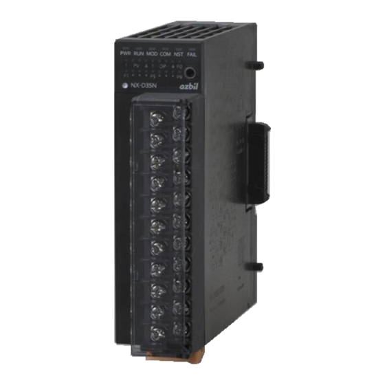
Chapter 1. Overview 1 - 3 Names and Functions of Parts ■ Controller module ● Main unit Indicators on the main unit vary depending on the model No. (functions). LED operation indicators PWR/RUN/MOD/COM/NST/FAIL PV1–4 operation indicator Loader jack OP1–4 operation indicator F0 operation indicator F1–9 operation indicator Push button... -
Page 27: Communication Box
For ring communications, use ports 3 and 4. * For internal use at Azbil. It is not possible to change the setting with the loader. ● Base ● NX-CB1_ _ _ _ _ _ ● NX-CB2_ _ _ _ _ _... -
Page 28: Communication Adapter
Chapter 1. Overview ■ Communication adapter ● For left side Ethernet port: Used to connect Ethernet cables. Side connector: Used for transmitting Ethernet signals. DIN rail locking tab: Used for locking on a DIN rail. ● For right side... -
Page 29: Terminal Adapter
Chapter 1. Overview ■ Terminal adapter ● For left side Loopback connector: Needed for chain connection ring communication. It is tted to the terminal adapter. Side connector: Used for transmitting Ethernet signals. DIN rail locking tab: Used for locking on a DIN rail. ●... -
Page 30: Operation Modes
Chapter 1. Overview 1 - 4 Operation Modes ■ Operation modes The following shows the state transitions in operation mode. Operation mode Hard failure IDLE RUN: All module functions are operating. IDLE: Module control has stopped. Hard failure: Hard failure of the module. Module control has stopped. ■... -
Page 31: Communication Availability In Each Operation Mode And Status
Chapter 1. Overview ■ Communication availability in each operation mode and status The following table lists communication availability in each operation mode and status. ROM version 3.00 [1_0_3] and later versions Available — Not Available ● Operation modes When an error occurs During AL53* AL54*... - Page 32 Chapter 1. Overview Note • 7 - 13, Start Delay at Power ON (page 7-27) (for more details on operation, including communication at power ON) • Table for ROM versions 2.02 [1_0_2] and earlier During Device operation Device operation startup mode: RUN mode: IDLE Host communications...
-
Page 33: Loop Modes
Chapter 1. Overview ■ Loop modes The following shows the state transitions in loop mode. RUN + AUTO mode READY + AUTO mode LSP mode RSP mode LSP mode RSP mode RUN/READY mode selection AT stopped AT stopped AT running AUTO/MANUAL AUTO/MANUAL mode selection... -
Page 35: Chapter 2. Installation
80 mm in front of it as space for air intake, removal, wiring, and maintenance. This device should be at least 100 mm away from other devices or rows of other NX-D15/25/35 devices. Do not install this device above heat-generating objects such as electric devices. -
Page 36: Terminal Block Installation And Removal
Chapter 2. Installation Do not install this product in a place with any of the following characteristics: • Temperature or humidity outside the specified high and low limits • Corrosive gases such as sulfide gas • Dust or soot • Airflow from a heating/cooling system or a fan •... - Page 37 Chapter 2. Installation ● Mounting method (1) Tilt the terminal block and insert the top of it into the groove in the case. (2) Next, push in the bottom of the terminal block. (3) Slide the lock lever to the right to lock the terminal block in place.
-
Page 38: Module Connection
Chapter 2. Installation ■ Module connection This unit can be connected to other modules with the left and right connectors on the base. Wiring can be kept to a minimum because connected modules share power and communications. The connection with the module on the right can be disabled using the RS-485 cutoff switch on the base. -
Page 39: Mounting Method
Chapter 2. Installation ■ Mounting method Modules must be installed on a DIN rail. After attaching the DIN rail, pull the locking tab out sufficiently and hook the base onto the DIN rail. Next, push the locking tab upwards until it clicks into place. Handling Precautions •... -
Page 40: Removing The Main Unit From The Base
Chapter 2. Installation ■ Removing the main unit from the base (1) Push the main unit in toward the base. (2) While pushing, press the tip of the lever on the top of the main unit. (3) While pressing the tip of the lever, rotate the main unit down to remove it. Handling Precautions •... -
Page 41: Chapter 3. Wiring
If there is a risk of a power surge caused by lightning, use a surge absorber (surge protector). Otherwise, there is a danger of fire or device failure. The NX-D15/25/35 does not operate for about 10 seconds after the power has been turned ON, depending on the settings. -
Page 42: Wiring Precautions
Before connecting this device to other instruments in parallel, check their conditions for connection carefully. • To ensure stable operation, the NX-D15/25/35 is designed not to operate for about ten seconds after the power is turned ON. • After wiring, check that there are no wiring mistakes before turning the power •... -
Page 43: Cables
Chapter 3. Wiring 3 - 2 Cables • For thermocouple input, connect the thermocouple wires to the terminals. If the wiring distance is long, or if a thermocouple has terminal connection, use compensating wires to extend the wiring. Be sure to use a compensating lead wire that is shielded. •... -
Page 44: Connecting Screw Terminals
Chapter 3. Wiring 3 - 3 Connecting Screw Terminals CAUTION Firmly tighten the terminal screws to the torque listed in the specifications. Insufficient tightening may cause fire. Do not use unused terminals as relay terminals. There is a danger of fire, electric shock, or device failure. Do not short out the output section. -
Page 45: Connecting Screwless Terminals
Chapter 3. Wiring 3 - 4 Connecting Screwless Terminals CAUTION Do not short out the output terminals. There is a danger of device failure. The method of connecting screwless terminals of the module is explained below. Handling Precautions • Do not install the screwless terminal block on a screw terminal block model. •... - Page 46 Chapter 3. Wiring ● Removing ferrules To remove a ferrule, press the button on the side of the hole for the ferrule with a screwdriver, and pull the ferrule out. Use a screwdriver with the following dimensions. Head width 2.0–3.5 mm, head thickness 0.4–0.6 mm...
-
Page 47: Terminal Wiring Diagram
Chapter 3. Wiring 3 - 5 Terminal Wiring Diagram Screw Screwless terminal terminal Terminal Terminal block block • Terminals A0 to AA Analog current/voltage Transistor output Isolated analog current/voltage (for position Transistor output output proportional control) output - - + -... -
Page 48: Power Wiring
Chapter 3. Wiring 3 - 6 Power Wiring ■ Power wiring WARNING Before removing, mounting, or wiring this device, be sure to turn off the power to this device and all connected devices. Otherwise, there is a danger of electric shock. CAUTION The total power consumption of all connected modules should be no more than 70 W. -
Page 49: Noise Countermeasures
Minimize the effect of electrical noise from the power supply. If there is a large amount of electrical noise from the power supply, use a line filter. (Azbil Corporation’s line filter model No.: 81442557-001) Use a CR filter for quick-rising noises such as impulse noise. -
Page 50: Power Supply Design
Chapter 3. Wiring ■ Power supply design The required power supply capacity depends on the system configuration. For this reason, the required power supply capacity must be calculated and checked. The procedure for power supply design is shown below. (1) Calculate the total power consumption of the modules that are used. (2) Determine the power supply capacity required, considering inrush current and derating. -
Page 51: Pv Input Connections
Chapter 3. Wiring 3 - 7 PV Input Connections Handling Precautions • Do not apply a voltage exceeding the rated power of this product. Excessive voltage could result in device failure. • Pay attention to the input polarity when wiring. •... -
Page 52: Pv Input (Pv4)
Chapter 3. Wiring ■ PV input (PV4) • Thermocouple • RTD • DC voltage (mV) • DC voltage (V) • DC current (mA) ■ MFB input (MFB1) CLOSE OPEN ■ MFB input (MFB2) CLOSE OPEN 3-12... -
Page 53: Transistor And Digital Output Connections
Chapter 3. Wiring 3 - 8 Transistor and Digital Output Connections Handling Precautions • If an inductive load (such as a motor or solenoid valve) is used, consider methods for absorbing surges, such as parallel connection of a diode. • Pay attention to the external power supply polarity when wiring. -
Page 54: Connection With A Solid-State Relay (Ssr)
2. Is the external power source within the SSR input voltage range and transistor output (digital output) allowable external power source voltage range for the module? ● Connection with Azbil Corporation PGM10F series Power: select a 5–24 V DC unit External... -
Page 55: Analog Current Output Connections
Chapter 3. Wiring 3 - 9 Analog Current Output Connections Handling Precautions • Do not connect or disconnect a load while power is being supplied to the module. Doing so might cause the module or load to fail. • The input impedance and wiring resistance of other modules must be within the allowable load resistance of the module. -
Page 56: Connection Example With The Avp300 (Output Type C)
The module can be connected to the AVP300 (input impedance: 300 Ω) if the following condition is satisfied. Maximum current × (load resistance + wiring resistance) < 6.6 V (because 300 Ω × 22 mA = 6.6 V) ● Connection with Azbil Corporation AVP300 Cable length: 100 m AVP300 Input impedance... -
Page 57: Analog Voltage Output Connections
Chapter 3. Wiring 3 - 10 Analog Voltage Output Connections Handling Precautions • Do not connect or disconnect a load while power is being supplied to the module. Doing so might cause the module or load to fail. • The input impedance of other modules must be within the allowable load resistance of the module. -
Page 58: Current Transformer Input Connections
Chapter 3. Wiring 3 - 11 Current Transformer Input Connections Handling Precautions • Do not connect or disconnect a load while power is being supplied to the module. Doing so might cause the module or load to fail. • Up to 2 crimp terminal lugs can be connected to the COM terminal of the module. -
Page 59: Digital Input (Di) Connections
Chapter 3. Wiring 3 - 12 Digital Input (DI) Connections Handling Precautions • The module’s digital inputs use a built-in power supply. Use dry (non-voltage) contacts for external contacts. • Use contacts that have sufficient switching capacity for terminal current when shorted and terminal voltage when open. -
Page 60: Ethernet Communication Connections
Chapter 3. Wiring 3 - 13 Ethernet Communication Connections Section 1-3, “Explanation of Module Features, ” and section 2, “Configuration of Ethernet Communications, ” in Network Instrumentation Module User’s Manual: Network Design Version, No. CP-SP-1313E (for Ethernet communication connections) 3-20... -
Page 61: Loader Cable Connections
Chapter 3. Wiring 3 - 14 Loader Cable Connections Loader jack Loader cable Plug Handling Precautions • Use a USB loader cable only. • Firmly insert the plug into the loader jack. • When removing or inserting the loader cable, hold the plug, not the cable. Do not pull the cable. -
Page 62: Communication Connections
Chapter 3. Wiring 3 - 15 RS-485 Communication Connections Do the wiring for CPL and Modbus RS-485 as shown below. This device DB (-) DA (+) RS-485 Handling Precautions • Attach terminating resistors (150 Ω ±5 %, ½ W min.) to both ends of the transmission line. - Page 63 • If the transmission line includes a device to which terminating resistors should not be connected (Azbil’s SDC15/25/26/35/36, DMC10, etc.), do not connect any terminating resistor to the external devices of the NX-D15/25/35 and communication lines. • This device does not have a frame ground (FG) terminal.
- Page 64 • If the transmission line includes a device to which terminating resistors should not be connected (Azbil’s SDC15/25/26/35/36, DMC10, etc.), do not connect any terminating resistor to the external devices of the NX-D15/25/35 and communication lines. • This device does not have a frame ground (FG) terminal.
-
Page 65: Electrical Noise Sources And Countermeasures
• High-voltage ignition devices The following are effective countermeasures for electrical noise. • CR filter for quick-rising noise Recommended CR filter Azbil model: 81446365-001 • Varistor for noise with high peak values Recommended varistor: Azbil model: 81446366-001 (for 100 V) -
Page 66: Input/Output Isolation
Chapter 3. Wiring 3 - 17 Input/Output Isolation A solid line indicates isolation from the rest of the circuit. • Output types other than S and G Power supply (including the side connectors)* Logic circuit Transistor output (channels 1–4)* Loader jack Analog current output (channels 1–4) RS-485 communications, Analog voltage output (channels 1–4) -
Page 67: Chapter 4. Functions Necessary For Control -1
Chapter 4. Functions Necessary for Control 4 - 1 How to Set the Loop Configuration First, select the basic loop configuration settings that directly affect PID control. Configure the following items. • Number of PID control loops • RSP (enable or disable) •... - Page 68 Heat/cool Position Cascade MV branching Compatible Loop type of loops control proportioning control output model No. — — — — NX-D15/25/35 — — — NX-D15/25/35 — NX-D15/25/35 NX-D35 — NX-D15/25/35 — — NX-D15/25/35 — NX-D25/35 NX-D25/35 Note 1: MFB input is available only for NX-D35 models with an output type of M (transistor output for position proportional control) or with option 4 (4 digital outputs for position proportional control).
-
Page 69: How To Set The Pv Input
Chapter 4. Functions Necessary for Control 4 - 2 How to Set the PV Input ■ Settings bank and data fields Folder name Bank name Item name Settings User level Input-output PV input Range type See the tables below Simple Standard Multi-function Decimal... -
Page 70: Valid Range Types
Chapter 4. Functions Necessary for Control ■ Valid range types Model No. Range type NX-D15 1–26 (thermocouple) ● ● ● ● NX-D25 41–52 (RTD) ● ● ● ● NX-D35 (4 channels) 81–91 (linear) ● ● ● ● 75–76 (MFB count value) —... -
Page 71: How To Set Range-Related Items
Chapter 4. Functions Necessary for Control 4 - 3 How to Set Range-Related Items Configure the settings that are appropriate for the range type that was set in section 4-2, “How to Set the PV Input” (page 4-3). ■ Settings bank and data fields Folder Bank name Item name... - Page 72 Chapter 4. Functions Necessary for Control Note • Aside from setting the range type as shown in 4 - 2, How to Set the PV Input (page 4-3), set range-related items as needed. Since settings are initialized automatically as in the examples shown below, re- setting is usually not necessary.
-
Page 73: How To Set Up Linear Scaling
Chapter 4. Functions Necessary for Control ■ How to set up linear scaling The linear scaling low limit and high limit are set when the range type is DC voltage or DC current. Set them to suit the output range (engineering range) of the connected module. -
Page 74: How To Set Up The Pv Filter
Chapter 4. Functions Necessary for Control ■ How to set up the PV filter The PV filter is a first-order lag filter used if the PV fluctuates sharply and repeatedly out of control or if it flutters due to noise, etc. The larger the setting is, the less frequently the PV changes. - Page 75 Chapter 4. Functions Necessary for Control Handling Precautions • If an alarm occurs at the alarm setting high/low limit, the target input value is clamped to the alarm setting high/low limit value. • Even if the alarm setting high and low limits are changed to values outside the alarm setting range that is determined by the range type, the alarm settings are not changed.
-
Page 76: How To Set The Pv Ratio And Pv Bias
Chapter 4. Functions Necessary for Control • Resistance temperature detector (RTD) Default alarm settings Range Sensor type type Low limit High limit Pt100 −200.0 °C 570.0 °C JPt100 −200.0 °C 570.0 °C Pt100 −200.0 °C 955.0 °C JPt100 −200.0 °C 640.0 °C Pt100 −140.0 °C... -
Page 77: Lsp Functions
Chapter 4. Functions Necessary for Control 4 - 4 LSP Functions Up to four SP groups can be selected for each loop. Additionally, the number of SP groups can be restricted by setting “Number of SP groups” in the setup bank. ■... -
Page 78: Sp Low And High Limits
Chapter 4. Functions Necessary for Control ■ SP low and high limits The SP high and low limits can be set for each loop in order to specify the SP range. Folder name Bank name Item name Settings User level SP low limit −19999 to +32000U Simple... -
Page 79: How To Set The Decimal Point Position
Chapter 4. Functions Necessary for Control 4 - 5 How to Set the Decimal Point Position The decimal point position in items related to the loop PV/SP can be set. ■ Settings bank and data fields Folder name Bank name Item name Settings User level... -
Page 80: How To Set The Loop Control Action
Chapter 4. Functions Necessary for Control 4 - 6 How to Set the Loop Control Action ■ Settings bank and data fields Folder name Bank name Item name Settings User level Simple Basic Loop control Control action 0: Reverse (heating) (basic) 1: Direct (cooling) Standard... - Page 81 Chapter 4. Functions Necessary for Control • Reverse (ON/OFF) ON/OFF control Di erential • Direct (ON/OFF) ON/OFF control Di erential ● Example: Heating and cooling MV assigned to output In this example, heating MV is assigned to analog current output 1 and cooling MV is assigned to analog current output 2 in loop 1 of an analog current output model.
-
Page 82: How To Set Outputs (Continuous Output And Time Proportional Output)
Chapter 4. Functions Necessary for Control 4 - 7 How to Set Outputs (continuous output and time proportional output) Setup items vary depending on the type of output and operation method. ■ Output types and applications Output type Application Transistor Time proportional output (MV) Digital output (DO) Analog current... - Page 83 Chapter 4. Functions Necessary for Control Each continuous output channel must be configured. Select the analog current and analog voltage ranges in Output range. Set the output type and loop/channel definition. In Output decimal point position, set the decimal point position for the output scaling low and high limits.
-
Page 84: Time Proportional Output Settings
Chapter 4. Functions Necessary for Control ■ Time proportional output settings Folder name Bank name Item name Settings User level Input- OUT/DO Output type* 1: Loop 1 MV Simple output output 2: Loop 1 heat MV (for heating/cooling control) Standard 3: Loop 1 cool MV (for heating/cooling control) Multi-function 4: Loop 2 MV... -
Page 85: On/Off Control Settings
Chapter 4. Functions Necessary for Control ■ ON/OFF control settings In the case of MV output for ON/OFF control, set as shown below. 5 - 13, ON/OFF Control (page 5-25) (for details) Folder name Bank name Item name Settings User level Input- OUT/DO Output type*... -
Page 86: How To Set Position Proportional Output
How to Set Position Proportional Output Handling Precautions • This function is not available on the NX-D15/25. If either of the following conditions is satisfied, up to 2 outputs for position proportioning can be used. • The model No. is NX-D35 and M (transistor output for position proportional control) was selected as the Output type when the product was ordered. -
Page 87: Position Proportioning Settings
Chapter 4. Functions Necessary for Control ■ Position proportioning settings Folder name Bank name Item name Settings User level Basic Position Output type 0: Stop time proportional control Simple proportioning 1: Loop 1 MV Standard 2: Loop 1 heat MV Multi-function 3: Loop 1 cool MV 4: Loop 2 MV... -
Page 88: Pv Channel Settings For Mfb
Chapter 4. Functions Necessary for Control ■ PV channel settings for MFB Folder name Bank name Item name Settings User level Input- PV input Range type 75: MFB 100–1000 Ω Simple output 76: MFB 1000–5000 Ω Standard Multi-function Decimal point position 0 (Do not change the default setting.) Temperature unit 0: Celsius (°C) (Do not change the default setting.) Alarm setting low limit −19999 (Do not change the default setting.) -
Page 89: Default Settings For Position Proportional Output Models
Chapter 4. Functions Necessary for Control ■ Default settings for position proportional output models ● Default setting for loop configuration Folder name Bank name Item name Default Basic Setup Loop type 1: 2 loops ● Default settings for position proportioning (position proportioning 1 and 2) Folder name Bank name Item name... -
Page 90: Settings
Chapter 4. Functions Necessary for Control ● Default settings for the NX-D35_ _ _ M_ _(position proportional control model) Folder name Bank name Item name Default Input- OUT/DO output OUT 1 output type 14: Opening output for position proportional output 1 output OUT 2 output type 13: Closing output for position proportional output 1... -
Page 91: Control Method Selection
Chapter 4. Functions Necessary for Control ■ Control method selection ● 0: MFB control + estimated position control If MFB input is normal, control the motor using the current MFB value. • If MFB input is abnormal, control the motor using the estimated MFB value. This is called estimated position control. -
Page 92: Dead Zone
Chapter 4. Functions Necessary for Control ● 2: MFB control + estimated position control • Estimated position control is always executed. Regardless of MFB wiring, this function controls the motor using the estimated MFB value. • If using this function, set the full opening time correctly. •... -
Page 93: Auto-Tuning
Chapter 4. Functions Necessary for Control ■ Auto-tuning If 0 (MFB control + estimated position control) or 1 (MFB control + close upon line break) is selected for Control method selection, be sure to set auto-tuning. Fully closed FB value, Fully open FB value, and Full opening time FB value are adjusted automatically. Adjustment is also supported by the SLP-NX. -
Page 94: Motor Wiring And Operation With Auto-Tuning
Chapter 4. Functions Necessary for Control Note • To stop tuning, write 0 (stop) to the auto-tuning using the Universal Monitor of the loader. • In the case of the following, each adjusted value returns to the previous (unadjusted) state and error AL22 (MFB1 adjustment error) or AL24 (MFB2 adjustment error) is generated. - Page 95 Chapter 4. Functions Necessary for Control Direct wiring Reverse wiring This device This device Open Close Open Close Motor Motor : Clockwise ( : Counterclockwise ( The module has a function to detect incorrect wiring of the motor and line breaks or short-circuits in the MFB.
- Page 96 Chapter 4. Functions Necessary for Control ● Operation during auto-tuning with normal direct wiring Operation Motor during OUT terminal status rotation Remarks (MFB count value) auto-tuning direction Closing OUT1 terminal status (OPEN) = OFF Becomes stable after If OUT2 terminal is ON and the OUT2 terminal status (CLOSE) = ON decreasing (4000 2000)
- Page 97 Chapter 4. Functions Necessary for Control ● Alarms due to incorrect wiring and their causes Operation Motor during OUT terminal status rotation Alarm display Cause (MFB count value) auto-tuning direction Closing OUT1 terminal status (OPEN) = OFF Becomes stable after AL22 G ...
-
Page 98: Input Errors And Line Breaks
Chapter 4. Functions Necessary for Control ■ Input errors and line breaks The following alarms are activated if an input error or line break occurs. G line break, Y line break, T line Input error break, multiline break MFB1 error High limit error: AL21 and AL05 AL21 and AL05 Low limit error: AL21 and AL06... -
Page 99: Wiring To A Motor
Chapter 4. Functions Necessary for Control ■ Wiring to a motor Wire correctly so that the valve starts opening when the terminal that sends signals for opening is energized. (Wire correctly so that the valve starts to close when the terminal that sends signals for closing is energized.) For details, refer to the user’s manual for the motor. -
Page 100: Connection Example With The Ecm3000
Chapter 4. Functions Necessary for Control ■ Connection example with the ECM3000 An example of wiring between ECM3000 and the module is shown below. If the NX-D35 has the default settings, wiring varies depending on the model number as shown below. For instrumentation with the ECM3000, be sure to see the user’s manual for the ECM3000. - Page 101 Chapter 4. Functions Necessary for Control ● Motor wiring for option 4 (4 digital outputs for position proportional control) Connection of position proportioning 1 2 3 4 5 6 7 ECM3000 OPEN CLOSE Connection of position proportioning 2 2 3 4 5 6 7 ECM3000 OPEN CLOSE...
- Page 102 -MEMO-...
-
Page 103: Chapter 5. Operation
Chapter 5. Operation 5 - 1 Operation Settings There are LED indicators and a button on the front of the main unit. The LEDs blink in 2 ways: fast blink (0.2 s cycle) and slow blink (1.4 s cycle). ■ PWR, RUN, MOD, COM, NST, FAIL Lighting patterns of the LEDs on the top are shown and described in the table. -
Page 104: Op1 To
Chapter 5. Operation ■ OP1 to 4 Lighting patterns of LEDs OP1–4 on the middle row are shown and described in the table below. LED name Color Lighting status Description Green Transistor output channel 1 ON Transistor output channel 1 OFF Analog current/voltage output channel 1 Green Transistor output channel 2 ON... -
Page 105: F0 To
Chapter 5. Operation ■ F0 to 9 It is possible to set the lighting conditions and pattern only for the normal lighting of LED F0 on the right end of the middle row and LEDs F1–9 on the bottom row. By default, the status of alarms and events is shown. -
Page 106: Display When Power Is Turned On
Chapter 5. Operation ■ Display when power is turned ON When the power comes on, LEDs are first lit as shown in the table below. Afterward, they indicate the state of operation. Lighting status of LED* Top LEDs Middle Bottom LEDs LEDs Order... - Page 107 Chapter 5. Operation ● ROM versions 2.02 [1_0_2] and earlier Lighting status of LED* Top LEDs Middle Bottom LEDs LEDs Status or process PV1–4 PWR RUN MOD COM NST FAIL OP1–4 F1–9 Module LED lighting function ...
-
Page 108: Restoring Base Eeprom Using The Button
Chapter 5. Operation ■ Restoring base EEPROM using the button Button operation can restore the base EEPROM and eliminate the mismatch between the main unit and base. At this time, the RS-485 and Ethernet communication settings stored on the base (except for the MAC address) are also set for the main unit. -
Page 109: Loop Modes
Chapter 5. Operation 5 - 2 Loop Modes The data settings related to the loop modes are shown in the table. 1 - 4, Operation Modes (page 1-8) (for an overview of the loop modes) ■ Settings bank and data fields (loop mode switchover) Folder name Bank name Item name... -
Page 110: How To Change The Control Mode And Parameters
Chapter 5. Operation 5 - 3 How to Change the Control Mode and Parameters To change control modes or parameters, use the SLP-NX (sold separately) or host communications. This section describes how to change control modes or parameters using the SLP-NX. ■... - Page 111 Chapter 5. Operation ● How to change settings Example: switching RUN to READY in PID control Note • The following method is an example. The same change can be performed with other operation methods. (1) Activate the SLP-NX. (2) Open the project stored in the PC as backup. (3) Connect the PC to the module.
-
Page 112: How To Manually Output The Mv (Auto/Manual)
Chapter 5. Operation 5 - 4 How to Manually Output the MV (AUTO/MANUAL) The MV can be manually output to each loop using the Universal Monitor. The procedure is as follows. (1) Display the desired loop using the Universal Monitor. (2) Switch AUTO to MANUAL in the [Setting] tab of the Numeric monitor. -
Page 113: How To Change To The Remote Sp (Rsp/Lsp)
Chapter 5. Operation 5 - 5 How to Change to the Remote SP (RSP/LSP) For a loop that already has an RSP, it is possible to switch the LSP to RSP or the reverse using the Universal Monitor. The procedure is as follows. (1) Display the desired loop using the Universal Monitor. -
Page 114: How To Stop Control By Switching Run To Ready
Chapter 5. Operation 5 - 6 How to Stop Control by Switching RUN to READY It is possible to switch RUN to READY or in reverse using the Universal Monitor. The procedure is as follows. (1) Display the desired loop using the Universal Monitor. (2) Switch RUN to READY in the [Setting] tab of the Numeric monitor. -
Page 115: How To Operate The Auto Tuning
Chapter 5. Operation 5 - 7 How to Operate the Auto Tuning It is possible to start/stop the auto-tuning (AT) using the Universal Monitor. The procedure is as follows. (1) Display the desired loop using the Universal Monitor. (2) Make sure that the PV is correct. Make sure that the control function is ready to use in both RUN and AUTO modes. -
Page 116: How To Change The Sp
Chapter 5. Operation 5 - 8 How to Change the SP There are several methods of changing the SP of any loop. ■ Changing the LSP used It is possible to change the SP of any loop using the Universal Monitor. The procedure is as follows. -
Page 117: How To Change The Pid
Chapter 5. Operation 5 - 9 How to Change the PID There are 2 methods of changing the PID constants: changing the PID settings and executing auto-tuning. ■ Changing the PID settings The PID constants can be changed using the Universal Monitor. The procedure is as follows. -
Page 118: How To Change The Event Action Point
Chapter 5. Operation 5 - 10 How to Change the Event Action Point The event action point is changed by using the SLP-NX. There are 2 event setting types: event main setting and event sub-setting. Some events have event main setting alone, and some have both types. -
Page 119: Pid Control
Chapter 5. Operation 5 - 11 PID Control If the control action is set to 0 (reverse action) or 1 (direct action), control is executed as follows. • When integral time ≠ 0 and derivative time ≠ 0, PID control is executed. •... -
Page 120: Pid Control Initialization
Chapter 5. Operation ■ PID control initialization • If the control method is not ON/OFF control, it can be displayed/set. • With the change in the PID group as a result of the SP value / SP group change, the manipulated variable (MV) may hover around the lower/upper limit or the PV may not change or overshoot. -
Page 121: Heating/Cooling Control
Chapter 5. Operation 5 - 12 Heating/Cooling Control If the control operation is set to 2 (Heating/cooling), heating and cooling are controlled. ■ Settings bank and data fields Folder Bank name Item name Settings User level name Basic Loop control Control action 0: Reverse (heating) Simple... -
Page 122: Heating/Cooling Control Calculation
Chapter 5. Operation ■ Heating/cooling control calculation Heat/cool control calculations are as follows. Heating Cooling PID group PID group Heat/cool selection PID constant Heating/cooling Heat MV PID calculation Limiter for MV high (reverse action control & low limits xed) Cool MV calculation (PID calculation results) -
Page 123: High And Low Limits For Heating Mv And Cooling Mv
Chapter 5. Operation ■ High and low limits for heating MV and cooling MV The MV high limit for cooling and MV low limit for cooling parameters are high and low limits for cooling output. The MV high limit for heating and MV low limit for heating parameters are high and low limits for heating output. - Page 124 Chapter 5. Operation Example: When the cooling MV does not reach the MV low limit for cooling Cool MV Heat MV 100.0 % MV high limit 100.0 % for cooling MV high limit for heating Actual low limit MV low limit MV low limit for heating for cooling...
- Page 125 Chapter 5. Operation Note • To prevent the cooling MV from being limited by the MV high limit, the approximation function in the NX-D25/35 can be used as shown below. Heating Cooling PID group PID group Heat/cool selection PID constant Heat MV Heat MV (after linearization)
- Page 126 Chapter 5. Operation Ex.: Use linearization table groups 1 and 2 to set high and low limits for the continuously output heating MV and cooling MV that are controlled by PID 1 Folder Bank name Item name Settings name (PID1) MV low limit 1 (PID1) MV high limit 1 100.0 (PID1) MV low limit for cooling 1...
-
Page 127: On/Off Control
Chapter 5. Operation 5 - 13 ON/OFF Control ON/OFF control action is set to 4 (reverse action (ON/OFF)) or 5 (direct action (ON/OFF)), ON/OFF control is executed as follows. The differential can be changed by switching PID groups. ■ Settings bank and data fields Folder Bank name Item name... -
Page 129: Chapter 6. Functions Often Used For Operations Other Than Control
Chapter 6. Functions Often Used for Operations Other Than Control 6 - 1 How to Use Events The ON/OFF status of the event is determined according to the conditions for each operation type. The ON/OFF result of the event can be output from the ON/OFF output terminals or digital output terminals. Additionally, the ON/OFF result status of the event can be used as internal contact input. -
Page 130: Example: Pv High Limit Alarm (Activated If An Error Occurs)
Chapter 6. Functions Often Used for Operations Other Than Control ■ Example: PV high limit alarm (activated if an error occurs) The following is an example where the OUT 1 output is turned ON if the PV of loop 1 exceeds 800 °C. In this example, the event function and output function are used. -
Page 131: Event Operation Type, Direct/Reverse, Hysteresis, Main Setting, And Sub-Setting
Chapter 6. Functions Often Used for Operations Other Than Control (3) Assign the ON/OFF status of event 1 to output 1. Configure the settings as shown below in the OUT/DO output bank setup. Folder Bank name Item name Settings User level name Input- OUT/DO output... - Page 132 Chapter 6. Functions Often Used for Operations Other Than Control Direct action Reverse action : ON/OFF switches at this value ●: ON/OFF changes at this value ● Operation type Setting : ON/OFF switches if this value is : ON/OFF switches if this value is ...
- Page 133 Chapter 6. Functions Often Used for Operations Other Than Control Direct action Reverse action : ON/OFF switches at this value ●: ON/OFF changes at this value ● Operation type Setting : ON/OFF switches if this value is : ON/OFF switches if this value is ...
- Page 134 Chapter 6. Functions Often Used for Operations Other Than Control Direct action Reverse action : ON/OFF switches at this value ●: ON/OFF changes at this value ● Operation type Setting : ON/OFF switches if this value is : ON/OFF switches if this value is ...
- Page 135 Chapter 6. Functions Often Used for Operations Other Than Control Direct action Reverse action : ON/OFF switches at this value ●: ON/OFF changes at this value ● Operation type Setting : ON/OFF switches if this value is : ON/OFF switches if this value is ...
-
Page 136: Loop/Channel Definition Setup
Chapter 6. Functions Often Used for Operations Other Than Control Direct action Reverse action : ON/OFF switches at this value ●: ON/OFF changes at this value ● Operation type Setting : ON/OFF switches if this value is : ON/OFF switches if this value is ... -
Page 137: Event Standby And Event State At Ready
Chapter 6. Functions Often Used for Operations Other Than Control ■ Event standby and EVENT state at READY Standby is a function by which, when this unit is turned ON or when READY mode is changed to RUN, the event does not turn ON even though the ON conditions are satisfied. -
Page 138: Event Decimal Point
Chapter 6. Functions Often Used for Operations Other Than Control SP changed (LSP or SP group) Hysteresis SP after change + event main setting SP before change + event main setting Event standby setting 0: No standby 1: Standby 2: Standby + standby when the SP is modi ed Handling Precautions •... -
Page 139: How To Use Internal Contact Input
Chapter 6. Functions Often Used for Operations Other Than Control 6 - 2 How to Use Internal Contact Input The internal contact input can take in ON/OFF data, such as a digital input (DI) that is specified for Input type, as internal contact input inside the instrument. -
Page 140: Example 2: Sp Group Selection Using Digital Input
Chapter 6. Functions Often Used for Operations Other Than Control ■ Example 2: SP group selection using digital input The following is an example where the multi-SP group (1–4) of loop 1 is selected using the DI 1 and DI 2 terminals. DI1 terminal Weighting = 1 DI2 terminal... -
Page 141: Operation Type
This function is compatible with ROM version 2.00 [1_0_1] and later versions of the NX-D25. This function is compatible with ROM version 2.00 [1_0_1] and later versions of the NX-D15. This function is compatible with ROM version 3.00 [1_0_3] and later versions of the NX-D25/35. -
Page 142: Input Type
Chapter 6. Functions Often Used for Operations Other Than Control ■ Input type Use this to specify the ON/OFF data that the internal contact input uses as input. This kind of ON/OFF data shows various kinds of instrument status and is called a standard bit. -
Page 143: How To Use Digital Output
Chapter 6. Functions Often Used for Operations Other Than Control 6 - 3 How to Use Digital Output ON/OFF data specified as the output type can be output from the digital output (DO) In addition, the ON or OFF status of the digital output can be latched. ■... -
Page 144: Output Type
Chapter 6. Functions Often Used for Operations Other Than Control ■ Output type Specify ON/OFF data to be output from the digital output. The ON/OFF data shows various instrument states and is called a standard bit. Set a standard bit code as an output type. Note •... -
Page 145: How To Use Multiple Sps
Chapter 6. Functions Often Used for Operations Other Than Control 6 - 4 How to Use Multiple SPs Multiple SPs can be set by combining an LSP value and a PID group definition for an SP group. Up to 4 SP groups per loop are provided. You can select one of these groups and use it for control. Loop 1 Loop 2 Loop 3... - Page 146 Chapter 6. Functions Often Used for Operations Other Than Control (3) Set data for the PID group. Configure the settings as shown below in the loop 1 PID bank. Folder Bank name Item name Settings User level name (Loop 1) Proportional band 1 Simple Standard (Loop 1) Integral time 1...
-
Page 147: How To Change The Lsp With A Constant Ramp
Chapter 6. Functions Often Used for Operations Other Than Control 6 - 5 How to Change the LSP with a Constant Ramp When changing the set value of the LSP or the SP group selection, it is possible to change the SP with a constant SP ramp. SP is changed Previous LSP New LSP... -
Page 148: How To Change The Rsp With A Constant Ramp
Chapter 6. Functions Often Used for Operations Other Than Control 6 - 6 How to Change the RSP with a Constant Ramp When the RSP is changed, the SP can be changed with a constant ramp. New RSP SP is changed Previous RSP RSP ramp-down Previous RSP... -
Page 149: Ct (Current Transformer) Input
Chapter 6. Functions Often Used for Operations Other Than Control 6 - 7 CT (Current Transformer) Input A module with the optional current transformer (CT) input can detect the status of a heater or actuator and measure (1) Heater burnout detection, overcurrent detection, and short-circuit detection (2) Current measurement using true RMS values (cycle can be set) Set CT operation for use of either of the above. - Page 150 Chapter 6. Functions Often Used for Operations Other Than Control Note • The current measurement range and the monitor data range are calculated using the formulas below. Low limit of the current measurement range (A) = Number of CT turns / (2000 × Number of CT power line passes) High limit of the current measurement range (A) = Number of CT turns / (16 ×...
-
Page 151: Settings Bank And Data Fields
Chapter 6. Functions Often Used for Operations Other Than Control ■ Settings bank and data fields Folder Bank name Item name Settings User level name Input- CT input CT operation 0: Continuous current measurement (clamp Simple output meter mode) Standard 1: Detection of heater burnout for terminal Multi- OUT1... -
Page 152: Ct Operation
Chapter 6. Functions Often Used for Operations Other Than Control ■ CT operation ● 0: Continuous current measurement (clamp meter mode) This function can detect current high limit errors using overcurrent detection and current low limit errors using heater burnout detection. Current is measured in the continuous current measurement cycle to update measured current when output ON. -
Page 153: Wait Time For Ct Measurement
Chapter 6. Functions Often Used for Operations Other Than Control Handling Precautions • If CT operation is set to one of settings 1–4 (Detection of heater burnout for terminal OUT1–4), heater burnout detection cannot measure time proportioning current at the OUT terminal used for S21 (Peak power suppression control). -
Page 154: Threshold Current For Determining Heater Burnout
Chapter 6. Functions Often Used for Operations Other Than Control ■ Threshold current for determining heater burnout If the measured current when output ON is below the setting, heater burnout is detected. If the setting is 0.0, detection is disabled. Note •... -
Page 155: Threshold Current For Determining A Short Circuit
Chapter 6. Functions Often Used for Operations Other Than Control ■ Threshold current for determining a short circuit If the measured current when output OFF exceeds the setting, a short-circuit is detected. If the setting is 0.0, detection is disabled. Note •... -
Page 156: Delay Time
Chapter 6. Functions Often Used for Operations Other Than Control ■ Delay time Set the same ON-delay time for heater burnout detection, overcurrent detection, and short-circuit detection. This delay timer is started and reset based on the conditions in the table below. Detection type Start condition Reset condition... -
Page 157: Condition For Restoring Status Before Measurement
Chapter 6. Functions Often Used for Operations Other Than Control ■ Condition for restoring status before measurement Set a standard bit code as the condition for restoring the status before current measurement. This function is used to abort burnout detection that continues while control has stopped after burnout is detected. -
Page 158: Timing For Updating Ct Current Measurement
Chapter 6. Functions Often Used for Operations Other Than Control Handling Precautions • The detection status of heater burnout, overcurrent, and short-circuit is reflected in the value of the standard bit. ■ Standard bit codes (page App.-11) • In the case of CTs connected to the output terminal (loop) of an analog current output model (Output type C in the model No.) or analog voltage output model (type D), even if CT operation is set for a setting from 1 to 4 (Detection of heater burnout for terminal OUT1–4), heater burnout and short circuit... -
Page 159: Continuous Current Measurement Cycle
Chapter 6. Functions Often Used for Operations Other Than Control Note • If CT operation is set to 1–4 (Detection of heater burnout for terminal OUT1–4), the update conditions for measured current are not satisfied if the control output is 0.0 % in READY mode or during heating. In this case, the previous value is retained as the current when the output is ON. -
Page 160: How To Detect Overcurrent
Chapter 6. Functions Often Used for Operations Other Than Control ■ How to detect overcurrent If the “Measured current when output ON” exceeds the setting, heater burnout is detected. Configure the following for overcurrent detection. • Set CT operation to a setting from 1 to 4 (Detection of heater burnout for terminal OUT1–4). -
Page 161: How To Measure The Current Of Time Proportional Output Of The Module Using A Solid-State Relay (Ssr)
Chapter 6. Functions Often Used for Operations Other Than Control ■ How to measure the current of time proportional output of the module using a solid- state relay (SSR) To measure current of time proportional output of the module using an SSR, configure the following. -
Page 163: Chapter 7. Functions Used As Required
7 - 1 Control Algorithm Handling Precautions • The NX-D15 does not support setting 2 (PID-B (PV derivative type)) for Control algorithm. • When using the module for cooperative control of the supervisor module, do not set “PID-B (PV derivative type). ”... -
Page 164: Mv When There Is A Pv Error
Chapter 7. Functions Used As Required 7 - 2 MV When There Is a PV Error The MV for PID calculation can be set so that it switches to any desired fixed value if a PV input error occurs when the mode is both RUN and AUTO. -
Page 165: Mv Change Limit
Chapter 7. Functions Used As Required 7 - 3 MV Change Limit Handling Precautions • This function is not available on the NX-D15. The amount of MV change per second can be limited by setting the MV change limit. ■ Setup data • Loop (extended) ■... -
Page 166: Mv Branching Output
Chapter 7. Functions Used As Required 7 - 4 MV Branching Output This function enables output to multiple loops by calculating ratio and bias for the output of the specified PID (the PID MV) and branching the output. ■ Loop mode diagram Loop 1 Loop 2 PID1... -
Page 167: Setup Data
Chapter 7. Functions Used As Required ■ Setup data • MV Branching Output ■ Example In the following example, loops 1–3 use ratios of 1.0, 0.9, and 0.8 and biases of 0.0, 2.0, and 3.0 respectively using PID MV1, while loop 4 independently uses a ratio of 0.7 and bias of 4.0 using PID MV4. - Page 168 Chapter 7. Functions Used As Required Example 1: RUN for all loops RUN/ Fixed value AUTO/ PID MV Loop MV Remarks READY output MANUAL Loop 1 Stopped Not used AUTO 50.0 % 50.0 % 50.0 % (PID MV1) × 1.0 + 0.0* Loop 2 Stopped Not used...
-
Page 169: Energy-Saving Time Proportioning
Chapter 7. Functions Used As Required 7 - 5 Energy-Saving Time Proportioning The energy-saving time proportional function can prevent multiple time proportional outputs from being generated at the same time. Example of operation when the energy-saving Example of operation when the energy-saving time proportional function is not used time proportional function is used Time proportional cycle... -
Page 170: Time Proportional Slave Channels
Chapter 7. Functions Used As Required ■ Time proportional slave channels Specify the slave output (the next output channel) for each output. For the last proportional slave channel in the group, assign its own number as its slave output. ■ Example The following tells how to create three energy-saving time proportioning groups and assign outputs 1–2, 4–6, and 7–8 to groups 1, 2, and 3 respectively. -
Page 171: Energy-Saving Delay Time
Chapter 7. Functions Used As Required ■ Energy-saving delay time Set the time after which the target channel starts output after the output from the previous channel is turned OFF. ( A in the figure) Use this delay so that the current output does not overlap that from the previous channel due to an operating delay of the actuator. -
Page 172: Phase Shift
Chapter 7. Functions Used As Required 7 - 6 Phase Shift This section explains the parameters of the phase shift function in the OUT/DO output bank. The phase shift function can be used to adjust the output phase for each time proportional output channel. This function can decrease the chances of simultaneous ON of time proportional outputs. -
Page 173: Approximation By Linearization Table
Handling Precautions • This function is not available on the NX-D15. Approximation by linearization can be used for PV inputs and outputs. There are eight linearization groups, each containing 20 points that can be set. (ROM versions 2.00 [1_0_1] and later) ■... -
Page 174: Example
Chapter 7. Functions Used As Required ■ Example In the following example, linear approximation for the PV1 input is done using linearization table 1. An input ranging from 0.0–100.0 is converted into 0.0–100.0 with a different characteristic. (1) Specify a group of the linearization table using the PV input. In the PV input bank, set as follows. -
Page 175: When The Breakpoint A Settings Are Not In Numerical Order By Size
Chapter 7. Functions Used As Required ■ When the breakpoint A settings are not in numerical order by size A line is constructed without the deviating points. It is possible not to use a breakpoint located in the middle. (Breakpoint 3 shown in the figure below.) It is possible not to use the excess breakpoints. -
Page 176: At (Auto-Tuning)
Chapter 7. Functions Used As Required 7 - 8 AT (Auto-tuning) When AT is executed, the type of AT can be selected to obtain results appropriate for the target control characteristics. One of the following three types of AT can be selected. 0: Normal (regular control characteristics) 1: Fast (response to disturbance) 2: Stable (priority on minimal up/down PV fluctuation) - Page 177 Chapter 7. Functions Used As Required When heat/cool control is used, execute AT with heating MV and cooling MV running. In the first half, the MV changes with the output low/high limit. In the second half, it changes in a somewhat narrow area. The following figure illustrates AT with the following settings: Heating/cooling control dead zone = 0.0 %, heat/cool control switchover point = 50.0 %, output low limit = 0.0 %, output high limit = 100.0 %...
-
Page 178: At Progress
Chapter 7. Functions Used As Required • If the loop or the instrument enters any of the following states while the AT is being activated, the AT is stopped with no change in the PID constant. • If the loop is in the following states: MANUAL mode, READY mode, after a PV high/low limit error, during fixed value output, or during MFB adjustment •... - Page 179 Chapter 7. Functions Used As Required ■ Example 2 The following describes how to configure loop 1 auto-tuning so that the AT result for derivative time is always 0.0. Set the AT adjustment factor. In the Loop (algorithm) bank, set as follows. Folder name Bank name Item name Settings...
-
Page 180: Zone Pid
Handling Precautions • This function is not available on the NX-D15. PID control can be performed using the Zone PID function. The zone PID is a function that selects a PID constant group from a group of 1–4 according to the value of the SP or PV. (ROM versions 2.00 [1_0_1] and later) -
Page 181: Example
Chapter 7. Functions Used As Required ■ Example The following example describes the zone PID function used with a PV starting from 100 °C in increments of 100 °C in loop 1. Configure the zones. Configure the settings as shown below in the loop (extended) setup. For zones 1–3, configure so that the values progressively increase. -
Page 182: Cold Junction Compensation
Chapter 7. Functions Used As Required 7 - 10 Cold Junction Compensation If the range type is thermocouple, the cold junction compensation method can be selected. ■ Settings bank and data fields Folder name Bank name Item name Settings User level Input- PV input Cold junction compensation... -
Page 183: Logical Operations
Chapter 7. Functions Used As Required 7 - 11 Logical Operations This unit can perform logical operations (0 and 1 Boolean operations) corresponding to various statuses and can use the logical operation results as ON/OFF outputs or internal contact inputs. 16 groups of logical operations are provided. -
Page 184: Settings Bank And Data Fields
Chapter 7. Functions Used As Required ■ Settings bank and data fields Folder name Bank name Item name Settings User level Standard Function Logical Calculation type 1: Calculation 1: (A and B) or (C and D) Operations 2: Calculation 2: (A or B) and (C or D) Multi-function 3: Calculation 3: (A or B or C or D) 4: Calculation 4: (A and B and C and D) -
Page 185: Input Assignments A-D
Chapter 7. Functions Used As Required (2) Assign the results of Logical operation 1 to digital output 1. Configure the settings as shown below in the OUT/DO output bank. Folder name Bank name Item name Settings User level Input- OUT/DO (OUT/DO output 1) Output type 1440: Logical operation 1 Simple... -
Page 186: Off-Delay Time
Chapter 7. Functions Used As Required ■ OFF-delay time Specify whether to use OFF delay for the calculation results. (The inverted results are used.) Results after inversion OFF-delay time ON-delay time (ms) Calculation results ON/OFF ■ Latch Select the latch operation for logical operations from the following. 0: No latch 1: Latch when ON 2: Latch when OFF (except OFF before power ON) -
Page 187: Ufled
Chapter 7. Functions Used As Required 7 - 12 UFLED The UFLED function assigns LED conditions (off, lit, blink) to 10 LED operation indicators (F0–F9). When the bit condition selected from the lighting condition changes to 1, the LED indicator is lit or blinks. ■... -
Page 188: Lighting Status
Chapter 7. Functions Used As Required ■ Lighting status 0: Off Always OFF 1: Lit Lit when lighting condition is ON. 2: Lit (reverse video) Lit when lighting condition is OFF. 3: Fast blink Fast blink when lighting condition is ON. 4: Fast blink (conditional reverse video) Fast blink when lighting condition is OFF. -
Page 189: Start Delay At Power On
Chapter 7. Functions Used As Required 7 - 13 Start Delay at Power ON The time between turning the power on and the start of operation can be extended to a maximum of 60 s. Operation starts once the total of the product-specific startup time required by this product (9 s), and the duration of this setting, has elapsed. -
Page 190: User-Defined Bits
Chapter 7. Functions Used As Required 7 - 14 User-Defined Bits User-defined bits are 32 ON/OFF variables that can be read and written using host or loader communication. ■ Example The following describes the settings required so that when User-defined bit 1 is turned ON or OFF the mode of loop 1 is switched to READY or RUN respectively. -
Page 191: User-Defined Number
Chapter 7. Functions Used As Required 7 - 15 User-Defined Number User-defined numbers are 16 numerical variables that can be read and written using host or loader communication. ■ Example The following is an example where the analog value from the host device is received via host communication and is then output. -
Page 192: Data Transfer Function Between Modules
Data Transfer Function between Modules Handling Precautions • This function is not available on the NX-D15. • This function is not available in any of the cooperative operation modes in the module to which multi-loop cooperative control is set. Do not set up the data transfer function between modules. - Page 193 Chapter 7. Functions Used As Required Handling Precautions • When configuring the data transfer function between modules, be sure to configure both the sending and the receiving module. If it is necessary to stop implementation of the data transfer function between modules on a module set up for its use, in order to use it for another purpose, clear all settings for the function and set an appropriate cycle period.
-
Page 194: Supported Functions
Chapter 7. Functions Used As Required Note • Chapter 5, “Function for Transmitting Data Between Modules, ” in Network Instrumentation Module User’s Manual: Network Design Version, CP-SP-1313E • "Setting Up the Inter-Module Data Transfer Function" in section 6-3, “Editing Parameters, ” in Network Instrumentation Module Smart Loader Package SLP-NX User’s Manual, CP-UM-5636E ■... -
Page 195: Reception Monitoring And Communication Timeout
Chapter 7. Functions Used As Required 7 - 17 Reception Monitoring and Communication Timeout This function monitors whether user-defined bits and user-defined values have been written normally through communications. Data Data Data Data Data writing writing writing writing writing Monitoring target (write data storage area) Timeout time Error occurrence Reception monitoring (standard bit) -
Page 196: Cycle Settings
Chapter 7. Functions Used As Required 7 - 18 Cycle Settings This section describes settings related to the control cycle (ROM versions 2.00 [1_0_1] and later) ■ Settings bank and data fields For the NX-D15 Folder name Bank name Item name Settings... -
Page 197: Input Assignment Function
0: Default 1: AI1. 2: AI2. 3: AI3. 4: AI4. 2048–3071: Standard numbers This function is available in ROM versions 2.00 [1_0_1] and later of the NX-D15. Note • 0 (Default) means that the same input channel as the loop number is used. -
Page 198: Just-Fitter
Chapter 7. Functions Used As Required 7 - 20 Just-FiTTER The Just-FiTTER function suppresses overshoot. ■ Settings bank and data fields Folder name Bank name Item name Settings User level Basic Loop control Just-FiTTER overshoot suppression 0–99 Multi-function (algorithm) factor Just-FiTTER settling band 0.00–10.00 ●... -
Page 199: Sp Lag
Chapter 7. Functions Used As Required 7 - 21 SP Lag SP lag suppresses the amount of MV change when the SP is changed. ■ Settings bank and data fields Folder name Bank name Item name Settings User level Basic Loop control SP lag factor 0.0–3200.0 s... -
Page 200: Internal Cascade Control
7 - 22 Internal Cascade Control Handling Precautions • This function is not available on the NX-D15. • This function is not available for multi-stage cascade controls that utilize three or more loops. Two sets of control loops can be used within a module to control master-slave cascades. Cascade control can be used for a maximum of two groups on 4 channels, and one group on 2 channels. -
Page 201: Scaling
Chapter 7. Functions Used As Required ■ Scaling This section explains the methods used to scale the master-side control loop MV setting to the slave-side control loop RSP. Scaling is updated for each cycle period according to the following formula. RSP = (MVm ÷... - Page 202 Chapter 7. Functions Used As Required ● Setting method This section explains the method for constructing a single loop internal cascade control on model NX-D25/35. Configure settings in the following order. (1) Set Loop type to 27 (1 Loop (RSP internal cascade)). (2) Set the scaling method for loop 1 (master side) in the Loop output (cascade) bank in the Basic folder.
-
Page 203: Idle/Sv Communication Error Operation
Chapter 7. Functions Used As Required 7 - 23 IDLE/SV Communication Error Operation “Signal to supervisor module timeout” determines the response to IDLE mode or a supervisor module communication error. In these two situations, the output terminals execute the set operation. This function is available for ROM version 3.00 [1_0_3] and later. - Page 204 Chapter 7. Functions Used As Required ● Output • For continuous output terminals or terminals where time proportional output is set as the output type, the output can be set in %. • Terminals for which the ON/OFF output type is set can be set to output ON/OFF. Handling Precautions •...
-
Page 205: Fixed Value Output
Fixed Value Output Handling Precautions • This function is not available on the NX-D15. • However, when the sum of the internal contact input weightings is 0 or when the fixed value group selection setting is not provided for internal contact input, fixed value output cannot be used. -
Page 206: Example
Chapter 7. Functions Used As Required ■ Example In the following example, digital inputs 1–4 are used to select fixed value outputs from 10.0 % to 70.0 % in steps of 10.0 in loop 1. (1) Set the fixed value output as follows. In the Loop output (MV) bank, set as follows. -
Page 207: Zener Barrier Adjustment And Wiring Resistance Correction
Chapter 7. Functions Used As Required 7 - 25 Zener Barrier Adjustment and Wiring Resistance Correction When using a zener barrier where PV input is a resistance temperature detector, be sure to adjust the zener barrier. This adjustment can be made even when not using a zener barrier, if the resistance of the three wires to the PV input terminals is different. -
Page 208: Setting Adjusted Values
Chapter 7. Functions Used As Required ■ Setting adjusted values (1) For Range type in the PV input bank, set the number of the resistance temperature detector (RTD). (2) Turn off the power to this device, and wire it in one of hard-wired states 1–3. When adjusting the zener barrier, use either wiring 1 or 2 as appropriate for the range type. - Page 209 Chapter 7. Functions Used As Required • The value written to “Command to store adjusted values” is not stored in nonvolatile memory. This value is 0 when the power is turned ON. • When undefined values are written to Command to store adjusted values, the adjusted value will not be stored.
-
Page 210: Rsp Tracking
Chapter 7. Functions Used As Required 7 - 26 RSP Tracking RSP tracking is a function to write the current RSP as the value of the LSP when RSP mode is switched to LSP mode. If multiple SP system groups are set, the number currently selected when the mode is changed is written to the LSP. Also, when the loop type is an internal cascade, the internal RSP is written as the slave LSP. -
Page 211: Chapter 8. Cpl Communication Function
■ Features The features of the module’s communication function are as follows. • Up to 31 NX-D15/25/35 units can be connected to a single master station (host device). • If the communication specification of the host unit is RS-232C, an RS-232C/RS- 485 communication converter (sold separately) is needed. -
Page 212: Communication Process
The communication process is as follows. (1) The host device (master station) sends an instruction message to one NX-D15/25/35 unit (slave station). (2) The slave station receives the instruction message and reads or writes according to the content of the message. -
Page 213: Message Structure
Chapter 8. CPL Communication Function 8 - 2 Message Structure ■ Message structure The following shows the structure of a message. Messages are broadly classified into two layers: the data link layer and the application layer. • Data link layer This layer contains the basic information required for communication (for example, the destination of the communication message and the information for checking that the message was accurately transmitted). - Page 214 Chapter 8. CPL Communication Function ● Definitions of data in the data link layer The following list gives definitions of the data in the data link layer. Number of Item Character code Meaning characters Start of message Station address 0 to 7FH are expressed as For identification of hexadecimal character codes.
- Page 215 Chapter 8. CPL Communication Function ● Checksum This value is for checking whether the message content was normally received without change due to some error (e.g., electrical noise). The checksum is expressed as two hexadecimal characters. • How to calculate the checksum (1) Add the character codes in the message from STX through ETX in single byte units.
-
Page 216: Application Layer
Chapter 8. CPL Communication Function ■ Application layer The table below shows the configuration of the application layer. Item Description Command RS (read decimal format data from consecutive addresses) WS (write decimal format data to consecutive addresses) RD (read hexadecimal format data from consecutive addresses) WD (write hexadecimal format data to consecutive addresses) RU (read hexadecimal format data from random addresses) WU (write hexadecimal format data to random addresses) -
Page 217: Description Of Commands
Chapter 8. CPL Communication Function 8 - 3 Description of Commands ■ Read fixed length continuous data command (RD command) Data in continuous data addresses is read in hexadecimal format. ● Instruction message Specifies the starting data address and the number of data items. The structure of the application layer in the instruction message is as follows. -
Page 218: Write Fixed Length Continuous Data Command (Wd Command)
Chapter 8. CPL Communication Function ■ Write fixed length continuous data command (WD command) Data is written in hexadecimal format to continuous data addresses. ● Instruction message Specifies the starting data address and at least one data item. The structure of the application layer in the instruction message is as follows. -
Page 219: Read Fixed Length Random Data Command (Ru Command)
Chapter 8. CPL Communication Function ■ Read fixed length random data command (RU command) Data is read from random (discrete) data addresses in hexadecimal format. ● Instruction message Specifies at least one data address. The structure of the application layer in the instruction message is as follows. -
Page 220: Write Fixed Length Random Data Command (Wu Command)
Chapter 8. CPL Communication Function ■ Write fixed length random data command (WU command) Data is written in hexadecimal format to random (discrete) data addresses. ● Instruction message Groups data addresses with data, and specifies at least one set. The structure of the application layer in the instruction message is as follows. -
Page 221: Read Continuous Data Command (Rs Command)
Chapter 8. CPL Communication Function ■ Read continuous data command (RS command) Data in continuous data addresses is read in a decimal format. ● Instruction message Specifies the starting data address and the number of data items. The structure of the application layer in the instruction message is as follows. -
Page 222: Write Continuous Data Command (Ws Command)
Chapter 8. CPL Communication Function ■ Write continuous data command (WS command) Data is written in decimal format to continuous data addresses. ● Instruction message Specifies the starting address and at least one data item. The structure of the application layer in the instruction message is as follows. (2) (4) (2) (1) Command (2) Data delimiter... -
Page 223: Data Address Definition
Chapter 8. CPL Communication Function 8 - 4 Data Address Definition ■ RAM and EEPROM areas of data addresses Data addresses are categorized as follows. Data address Item Remarks Hexadecimal Decimal 100 to FFF 256 to EEPROM access Data is written to both RAM and EEPROM, 4095 data address but it is read only from RAM. -
Page 224: Numerical Representation In The Application Layer
Chapter 8. CPL Communication Function 8 - 5 Numerical Representation in the Application Layer The numeric values in the application layer include the data address, number of data items, and data values. Depending on the command, hexadecimal or decimal notation is used. This same method of notation is shared by the instruction message and the response message. -
Page 225: Decimal
Chapter 8. CPL Communication Function ■ Decimal The decimal specifications are shown in the table below. In the data address, a capital letter W (57H) is added immediately after the decimal number. If the message does not follow the specifications, the module does not process the instruction message and instead returns an error response. -
Page 226: End Codes
Chapter 8. CPL Communication Function 8 - 6 End Codes The result of the application layer process for the instruction message can be understood from the end code of the response message. There are two levels of result other than “Normal. ” An “Error” occurs when nothing was processed, and a “Warning” occurs when there is a possibility that some kind of processing was done. -
Page 227: Reception And Transmission Timing
Chapter 8. CPL Communication Function 8 - 7 Reception and Transmission Timing ■ Timing specifications for instruction and response messages For the timing of instruction message transmission from the master station and response message transmission from the slave station, take the following into account. -
Page 229: Chapter 9. Modbus Communication Function
■ Features The features of the module’s communication function are as follows: • Up to 31 NX-D15/25/35 units can be connected to a single master station (host device). • If the communication specification of the host unit is RS-232C, an RS-232C/RS- 485 communication converter (sold separately) is needed. -
Page 230: Settings
The communication process is as follows: (1) The host device (master station) sends an instruction message to one NX-D15/25/35 unit (slave station). (2) The slave station receives the instruction message and reads or writes according to the content of the message. -
Page 231: Message Structure
Chapter 9. Modbus Communication Function 9 - 2 Message Structure ■ Message structure The following shows the structure of a message. ● Modbus/ASCII Messages other than the start code and end code all use hexadecimal ASCII codes. A MODBUS/ASCII message consists of (1) to (5) below. The command (content sent from the master station) and the response (content returned from the slave station) are stored in (3). - Page 232 Chapter 9. Modbus Communication Function ● End code (CR/LF) This indicates the end of the message. Immediately after LF is received, the device enters a state in which it is allowed to process the received message. Note • The following is an example of the check code (LRC) calculation. Message example 3AH (start of the message) 30H (first byte of the station address)
- Page 233 Chapter 9. Modbus Communication Function ● Station address Of the messages that this controller receives, it responds only to those that mention its station address. Station addresses in the messages are one byte. However, if the station address is set to 0, the module does not respond even if 0 is its station address.
-
Page 234: Command Type
Chapter 9. Modbus Communication Function ● Determining the end of one frame The end of the message (end of 1 frame) is determined when the period of time during which no character is received exceeds the time specified for the transmission speed. - Page 235 Chapter 9. Modbus Communication Function Note • For details on the specifications for Modbus communication, refer to the following. Modicon Modbus Protocol Reference Guide (PI-MBUS-300 Rev. J) by Modicon, Inc. OPEN Modbus/TCP SPECIFICATION Release 1.0) by Schneider Electric...
-
Page 236: Description Of Commands
Chapter 9. Modbus Communication Function 9 - 3 Description of Commands ■ Read multiple data items command (03H) Data in continuous data addresses is read in hexadecimal format. ● Instruction message Specifies the starting data address and the number of data items. The structure of this message is as follows. - Page 237 Chapter 9. Modbus Communication Function ● Response message The structure of this message is as follows. Modbus/ASCII • Normal example 3AH 30H 41H 30H 33H 30H 34H 30H 33H 30H 31H 30H 30H 30H 33H 45H 38H 0DH 0AH CR LF (1) Start code (2) Station address (3) Function code...
-
Page 238: Write Multiple Data Items Command (10H)
Chapter 9. Modbus Communication Function ■ Write multiple data items command (10H) Writing is performed in hexadecimal format to data in continuous data addresses. ● Instruction message Specifies the starting data address and at least one data item. The structure of this message is as follows. -
Page 239: Write 1 Data Item Command (06H)
Chapter 9. Modbus Communication Function Note • The response message in the case of an error is the same as for the Read multiple data items command. ■ Write 1 data item command (06H) Data is written to a data address in hexadecimal notation. ●... -
Page 240: Numeric Value Expression
Chapter 9. Modbus Communication Function 9 - 4 Numeric Value Expression Data addresses, the number of data items, and data values are expressed using hexadecimal notation. The numeric representation varies depending on whether the communication type is Modbus ASCII or Modbus RTU. The same notation method is shared by the instruction message and the response message. - Page 241 Chapter 9. Modbus Communication Function Handling Precautions • In Modbus communication, numeric values are expressed in order from the high-order to the low-order bit (big endian). 9-13...
-
Page 242: Specifications Common With Cpl Communication Function
Chapter 9. Modbus Communication Function 9 - 5 Specifications Common with CPL Communication Function ■ RAM and EEPROM areas of data addresses 8 - 4, Data Address Definition (page 8-13) ■ Specifications of RS-485 driver control timing 8 - 7, Reception and Transmission Timing (page 8-17) 9-14... -
Page 243: Chapter 10. Cpl/Tcp Communication Function
Chapter 10. CPL/TCP Communication Function 10 - 1 Overview of Communication The module can communicate with a host device using the CPL/TCP protocol, which is compliant with Ethernet TCP/IP. This function is available for ROM version 3.00 [1_0_3] and later. ■... -
Page 244: Communication Process
Chapter 10. CPL/TCP Communication Function ■ Communication process With CPL/TCP, the TCP/IP socket interface is used for communications. The TCP/ IP socket interface is used in different ways depending on the host device, but this section will explain the method for an ordinary computer. (1) A TCP/IP socket connection is established from the host device (master station) to one unit (slave station). -
Page 245: Message Structure
Chapter 10. CPL/TCP Communication Function 10 - 2 Message Structure ■ Message structure The following shows the message structure. Messages are broadly classified into two layers: the data link layer and the application layer. • Data link layer This layer contains the basic information required for communication (for example, the destination of the communication message and the information for checking that the message was accurately transmitted). - Page 246 Chapter 10. CPL/TCP Communication Function ● Definitions of data in the data link layer The following list gives definitions of the data in the data link layer. Number of Item Character code Meaning characters Start of message Station address 0 to 7FH are expressed as For identification of hexadecimal character codes.
- Page 247 Chapter 10. CPL/TCP Communication Function ● Checksum This value is for checking whether the message content was normally received without change due to some error (e.g., electrical noise). The checksum is expressed as two hexadecimal characters. • How to calculate the checksum (1) Add the character codes in the message from STX through ETX in single byte units.
-
Page 248: Application Layer
Chapter 10. CPL/TCP Communication Function ■ Application layer The table below shows the configuration of the application layer. Item Description Command RS (read decimal format data from consecutive addresses) WS (write decimal format data to consecutive addresses) RD (read hexadecimal format data from consecutive addresses) WD (write hexadecimal format data to consecutive addresses) RU (read hexadecimal format data from random addresses) WU (write hexadecimal format data to random addresses) -
Page 249: Description Of Commands
Chapter 10. CPL/TCP Communication Function 10 - 3 Description of Commands ■ Read fixed length continuous data command (RD command) Data in continuous data addresses is read in hexadecimal format. ● Instruction message Specifies the starting data address and the number of data items. The structure of the application layer in the instruction message is as follows. -
Page 250: Write Fixed Length Continuous Data Command (Wd Command)
Chapter 10. CPL/TCP Communication Function ■ Write fixed length continuous data command (WD command) Data is written in hexadecimal format to continuous data addresses. ● Instruction message Specifies the starting data address and at least one data item. The structure of the application layer in the instruction message is as follows. -
Page 251: Read Fixed Length Random Data Command (Ru Command)
Chapter 10. CPL/TCP Communication Function ■ Read fixed length random data command (RU command) Data is read from random (discrete) data addresses in hexadecimal format. ● Instruction message Specifies at least one data address. The structure of the application layer in the instruction message is as follows. -
Page 252: Write Fixed Length Random Data Command (Wu Command)
Chapter 10. CPL/TCP Communication Function ■ Write fixed length random data command (WU command) Data is written in hexadecimal format to random (discrete) data addresses. ● Instruction message Groups data addresses with data, and specifies at least one set. The structure of the application layer in the instruction message is as follows. -
Page 253: Read Continuous Data Command (Rs Command)
Chapter 10. CPL/TCP Communication Function ■ Read continuous data command (RS command) Data in continuous data addresses is read in a decimal format. ● Instruction message Specifies the starting data address and the number of data items. The structure of the application layer in the instruction message is as follows. -
Page 254: Write Continuous Data Command (Ws Command)
Chapter 10. CPL/TCP Communication Function ■ Write continuous data command (WS command) Data is written in decimal format to continuous data addresses. ● Instruction message Specifies the starting address and at least one data item. The structure of the application layer in the instruction message is as follows. (2) (4) (2) (1) Command (2) Data delimiter... -
Page 255: Data Address Definition
Chapter 10. CPL/TCP Communication Function 10 - 4 Data Address Definition ■ RAM and EEPROM areas of data addresses Data addresses are categorized as follows. Data address Item Remarks Hexadecimal Decimal 100 to FFF 256 to EEPROM access data Data is written to both RAM and EEPROM, 4095 address but it is read only from RAM. -
Page 256: Numerical Representation In The Application Layer
Chapter 10. CPL/TCP Communication Function 10 - 5 Numerical Representation in the Application Layer The numeric values in the application layer include the data address, number of data items, and data values. Depending on the command, hexadecimal or decimal notation is used. The same method of notation method is shared by the instruction message and the response message. -
Page 257: Decimal
Chapter 10. CPL/TCP Communication Function ■ Decimal The decimal specifications are shown in the table below. In the data address, a capital letter W (57H) is added immediately after the decimal number. If the message does not follow the specifications, the module does not process the instruction message and instead returns an error response. -
Page 258: End Codes
Chapter 10. CPL/TCP Communication Function 10 - 6 End Codes The result of the application layer process for the instruction message can be understood from the end code of the response message. There are two levels of result other than “Normal. ” An “Error” occurs when nothing was processed, and a “Warning” occurs when there is a possibility that some kind of processing was done. -
Page 259: Chapter 11. Modbus/Tcp Communication Function
Chapter 11. Modbus/TCP Communication Function 11 - 1 Overview of Communication The module can communicate with a host device using the Modbus/TCP protocol, which is compliant with Ethernet TCP/IP. ■ Features The features of the module’s communication function are as follows. •... -
Page 260: Communication Process
Chapter 11. Modbus/TCP Communication Function ■ Communication process Modbus TCP uses the TCP/IP socket interface for communication. The TCP/IP socket interface is used in different ways depending on the host device, but this section will explain the method for an ordinary computer. (1) A TCP/IP socket connection is established from the host device (master station) to one unit (slave station). -
Page 261: Message Structure
Chapter 11. Modbus/TCP Communication Function 11 - 2 Message Structure ■ Message structure A TCP/IP frame is used. A Modbus/TCP message is shown in the TCP data section. ● Modbus/TCP (4) (5) (1) Transaction Identifier (2 bytes) No special definition (2) Protocol Identifier (2 bytes) 0000H for Modbus protocol (3) Length (2 bytes) -
Page 262: Exception Code
Chapter 11. Modbus/TCP Communication Function ■ Exception code When a response message has an error, the exception code shown below is put after the function code. Error type Exception code Description Illegal function code 01 (2 bytes) Function code not supported by this device Illegal data address 02 (2 bytes) Data address that cannot be read/written... -
Page 263: Description Of Commands
Chapter 11. Modbus/TCP Communication Function 11 - 3 Description of Commands ■ Application section The following notation indicates 1 byte of data in hexadecimal notation (high is nibble on the left). ■ Read multiple data items command (03H) ● For one data item •... -
Page 264: Write Multiple Data Items Command (10H)
Chapter 11. Modbus/TCP Communication Function ■ Write multiple data items command (10H) ● For one data item • Request (1) Function code (Write Multiple Registers) (2) Starting data address (3) Number of read records (= 1) (4) Number of bytes (= number of data items × 2) (5) Write data •... -
Page 265: Write 1 Data Item Command (06H)
Chapter 11. Modbus/TCP Communication Function ■ Write 1 data item command (06H) • Request (1) Function code (Write Single Register) (2) Write address (3) Write data • Normal response (1) Function code (Write Single Register) (2) Write address (3) Write data (echoed back) •... -
Page 267: Chapter 12. List Of Communication Data -1
Chapter 12. List of Communication Data Comments on the table 12-2 Monitor/Communications Profile 12-3 Monitor/Loop Mode 12-5 Monitor/Monitor 12-6 Monitor/Remaining Delay Time 12-8 Monitor/Computation Result 12-9 Monitor/User-defined Bit 12-10 Monitor/User-defined Number 12-11 Standard Bit/Standard Bit 12-12 Standard Numerical Code/Standard Numerical Code 12-17 Communications/Ethernet Communications 12-20... - Page 268 Chapter 12. List of Communication Data ■ Comments on the table ● The meaning of the symbols in the RAM/EEPROM Read/Write columns is as follows. No symbol: Possible ×: Not possible Handling Precautions • When reading the EEPROM address, data in the RAM is read in the same manner as the reading of the RAM address.
- Page 269 Chapter 12. List of Communication Data Monitor/Communications Profile RAM address EEPROM address EEPROM Decimal Folder name Bank name Code Item point Notes Decimal Decimal Read Write Read Write info. Monitor Comm. (device) RUN/READY 14352 3810 30736 7810 × × — Monitor Comm.
- Page 270 Chapter 12. List of Communication Data Monitor/Communications Profile RAM address EEPROM address EEPROM Decimal Folder name Bank name Code Item point Notes Decimal Decimal Read Write Read Write info. Monitor Comm. (current PID) Current proportional band 14848 3A00 31232 7A00 Monitor Comm.
- Page 271 Chapter 12. List of Communication Data Monitor/Loop Mode RAM address EEPROM address EEPROM Decimal Folder name Bank name Code Item point Notes Decimal Decimal Read Write Read Write info. Monitor Loop mode RUN/READY 6960 1B30 23344 5B30 — Monitor Loop mode AUTO/MANUAL 6961 1B31...
- Page 272 Chapter 12. List of Communication Data Monitor/Monitor RAM address EEPROM address EEPROM Decimal Folder name Bank name Code Item point Notes Decimal Decimal Read Write Read Write info. Monitor Alarm Alarm information 1 10288 2830 26672 6830 × × — ●...
- Page 273 Chapter 12. List of Communication Data Monitor/Monitor RAM address EEPROM address EEPROM Decimal Folder name Bank name Code Item point Notes Decimal Decimal Read Write Read Write info. Monitor AO percent AO percent data 10453 28D5 26837 68D5 × × Monitor AO percent AO percent data...
- Page 274 Chapter 12. List of Communication Data Monitor/Remaining Delay Time RAM address EEPROM address EEPROM Decimal Folder name Bank name Code Item point Notes Decimal Decimal Read Write Read Write info. Monitor Remaining delay time Remaining delay time 10512 2910 26896 6910 ×...
- Page 275 Chapter 12. List of Communication Data Monitor/Computation Result RAM address EEPROM address EEPROM Decimal Folder name Bank name Code Item point Notes Decimal Decimal Read Write Read Write info. Monitor Computation result Instrument internal 10608 2970 26992 6970 × × —...
- Page 276 Chapter 12. List of Communication Data Monitor/User-defined Bit RAM address EEPROM address EEPROM Decimal Folder name Bank name Code Item point Notes Decimal Decimal Read Write Read Write info. Monitor User-defined bit User-defined bits 1 to 16 10080 2760 26464 6760 —...
- Page 277 Chapter 12. List of Communication Data Monitor/User-defined Number RAM address EEPROM address EEPROM Decimal Folder name Bank name Code Item point Notes Decimal Decimal Read Write Read Write info. Monitor User-defined number User-defined number 1 12224 2FC0 28608 6FC0 — Monitor User-defined number User-defined number 2...
- Page 278 Chapter 12. List of Communication Data Standard Bit/Standard Bit RAM address EEPROM address EEPROM Decimal Folder name Bank name Code Item point Notes Decimal Decimal Read Write Read Write info. Standard bit code Standard bit code (1024 to 1151) Always 0 (Off ) 17664 4500 —...
- Page 279 Chapter 12. List of Communication Data Standard Bit/Standard Bit RAM address EEPROM address EEPROM Decimal Folder name Bank name Code Item point Notes Decimal Decimal Read Write Read Write info. Standard bit code Standard bit code (1408 to 1535) User-defined bit 1 18048 4680 —...
- Page 280 Chapter 12. List of Communication Data Standard Bit/Standard Bit RAM address EEPROM address EEPROM Decimal Folder name Bank name Code Item point Notes Decimal Decimal Read Write Read Write info. Standard bit code Standard bit code (1536 to 1663) RS-485 status 18185 4709 —...
- Page 281 Chapter 12. List of Communication Data Standard Bit/Standard Bit RAM address EEPROM address EEPROM Decimal Folder name Bank name Code Item point Notes Decimal Decimal Read Write Read Write info. Standard bit code Standard bit code (1792 to 1919) MFB1 T/multiline break 18516 4854 —...
- Page 282 Chapter 12. List of Communication Data Standard Bit/Standard Bit RAM address EEPROM address EEPROM Decimal Folder name Bank name Code Item point Notes Decimal Decimal Read Write Read Write info. Standard bit code Standard bit code (1920 to 2047) Transmission timeout 18620 48BC —...
- Page 283 Chapter 12. List of Communication Data Standard Numerical Code/Standard Numerical Code RAM address EEPROM address EEPROM Decimal Folder name Bank name Code Item point Notes Decimal Decimal Read Write Read Write info. Standard numerical Standard numerical code (2048 Always 0.0 18688 4900 —...
- Page 284 Chapter 12. List of Communication Data Standard Numerical Code/Standard Numerical Code RAM address EEPROM address EEPROM Decimal Folder name Bank name Code Item point Notes Decimal Decimal Read Write Read Write info. Standard numerical Standard numerical code (2304 Loop 2 SP (in use) 18977 4A21 —...
- Page 285 Chapter 12. List of Communication Data Standard Numerical Code/Standard Numerical Code RAM address EEPROM address EEPROM Decimal Folder name Bank name Code Item point Notes Decimal Decimal Read Write Read Write info. Standard numerical Standard numerical code (2432 Loop 2 deviation (PV - SP) 19169 4AE1 —...
- Page 286 Chapter 12. List of Communication Data Communications/Ethernet Communications RAM address EEPROM address EEPROM Decimal Folder name Bank name Code Item point Notes Decimal Decimal Read Write Read Write info. Communication Ethernet communications MAC address 1 — — 0320 × × ×...
- Page 287 Chapter 12. List of Communication Data Communications/RS-485 Communications RAM address EEPROM address EEPROM Decimal Folder name Bank name Code Item point Notes Decimal Decimal Read Write Read Write info. Communication RS-485 communication Communications type — — 26624 6800 — Communication RS-485 communication Station address —...
- Page 288 Chapter 12. List of Communication Data Basic/Setup RAM address EEPROM address EEPROM Decimal Folder name Bank name Code Item point Notes Decimal Decimal Read Write Read Write info. Basic Setup SP system group 8818 2272 25202 6272 — Basic Setup Start delay at power ON 8820 2274...
- Page 289 Chapter 12. List of Communication Data Basic/Loop (Input) RAM address EEPROM address EEPROM Decimal Folder name Bank name Code Item point Notes Decimal Decimal Read Write Read Write info. Basic Loop (input) Assigned PV 10704 29D0 27088 69D0 — Basic Loop (input) Assigned RSP 10705...
- Page 290 Chapter 12. List of Communication Data Basic/Loop RAM address EEPROM address EEPROM Decimal Folder name Bank name Code Item point Notes Decimal Decimal Read Write Read Write info. Basic Loop control (basic) Loop PV/SP decimal point 8048 1F70 24432 5F70 —...
- Page 291 5FF3 Not available for 2 channels Basic Loop (extended) MV increase change limit 8180 1FF4 24564 5FF4 Not available on NX-D15 or for 2 channels Basic Loop (extended) MV decrease change limit 8181 1FF5 24565 5FF5 Not available on NX-D15 or for...
- Page 292 Chapter 12. List of Communication Data Basic/Loop RAM address EEPROM address EEPROM Decimal Folder name Bank name Code Item point Notes Decimal Decimal Read Write Read Write info. Basic Loop (algorithm) AT adjustment factor, 8240 2030 24624 6030 proportional band Basic Loop (algorithm) AT adjustment factor,...
- Page 293 60D4 Not available for 2 channels Basic Loop output (MV) Fixed value output 1 8405 20D5 24789 60D5 Not available on NX-D15 or for 2 channels Basic Loop output (MV) Fixed value output 2 8406 20D6 24790 60D6 Not available on NX-D15 or for...
- Page 294 6ADC Not available on NX-D15 Basic Loop output (cascade) SP scaling method 10976 2AE0 27360 6AE0 — Not available on NX-D15 or for 2 channels Basic Loop output (cascade) Output scaling low limit 10977 2AE1 27361 6AE1 PID_PV Not available on NX-D15 or for...
- Page 295 Chapter 12. List of Communication Data Basic/IDLE/SV com error op RAM address EEPROM address EEPROM Decimal Folder name Bank name Code Item point Notes Decimal Decimal Read Write Read Write info. Basic IDLE/SV com error op Output type 12000 2EE0 28384 6EE0 —...
- Page 296 Chapter 12. List of Communication Data Basic/Position Proportioning RAM address EEPROM address EEPROM Decimal Folder name Bank name Code Item point Notes Decimal Decimal Read Write Read Write info. Basic Position proportioning Output type 12080 2F30 28464 6F30 — Only with NX-D35 (position proportional control) Basic Position proportioning...
- Page 297 Chapter 12. List of Communication Data Basic/Position Proportioning Adjustment RAM address EEPROM address EEPROM Decimal Folder name Bank name Code Item point Notes Decimal Decimal Read Write Read Write info. Basic Position proportioning Auto-tuning 10816 2A40 27200 6A40 — Only with NX-D35 (position adjustment proportional control) Basic...
- Page 298 Chapter 12. List of Communication Data Input-output/PV Input RAM address EEPROM address EEPROM Decimal Folder name Bank name Code Item point Notes Decimal Decimal Read Write Read Write info. Input-output PV input Range type 9024 2340 25408 6340 — Input-output PV input Decimal point position 9025 2341...
- Page 299 Chapter 12. List of Communication Data Input-output/Continuous Output RAM address EEPROM address EEPROM Decimal Folder name Bank name Code Item point Notes Decimal Decimal Read Write Read Write info. Input-output Continuous output Output range 9216 2400 25600 6400 — Input-output Continuous output Output type 9217 2401...
- Page 300 Chapter 12. List of Communication Data Input-output / OUT/DO Output RAM address EEPROM address EEPROM Decimal Folder name Bank name Code Item point Notes Decimal Decimal Read Write Read Write info. Input-output OUT/DO output Output type 9328 2470 25712 6470 —...
- Page 301 Chapter 12. List of Communication Data Input-output/Zener Barrier Adjustment RAM address EEPROM address EEPROM Decimal Folder name Bank name Code Item point Notes Decimal Decimal Read Write Read Write info. Input-output Zener barrier adjst. Command to store adjusted values 10848 2A60 27232 6A60...
- Page 302 Chapter 12. List of Communication Data Input-output/CT Input RAM address EEPROM address EEPROM Decimal Folder name Bank name Code Item point Notes Decimal Decimal Read Write Read Write info. Input-output CT input CT operation 11152 2B90 27536 6B90 — Input-output CT input Wait time for CT measurement 11153 2B91...
- Page 303 Chapter 12. List of Communication Data SP/SP Group Selection RAM address EEPROM address EEPROM Decimal Folder name Bank name Code Item point Notes Decimal Decimal Read Write Read Write info. SP group selection SP group selection 4096 1000 20480 5000 —...
- Page 304 Chapter 12. List of Communication Data SP/LSP RAM address EEPROM address EEPROM Decimal Folder name Bank name Code Item point Notes Decimal Decimal Read Write Read Write info. LSP1 4112 1010 20496 5010 PID_PV PID group definition 1 (for LSP) 4113 1011 20497...
- Page 305 Chapter 12. List of Communication Data SP/RSP RAM address EEPROM address EEPROM Decimal Folder name Bank name Code Item point Notes Decimal Decimal Read Write Read Write info. 4240 1090 20624 5090 × × PID_PV PID group definition 4241 1091 20625 5091 −...
- Page 306 Chapter 12. List of Communication Data SP/SP Configuration RAM address EEPROM address EEPROM Decimal Folder name Bank name Code Item point Notes Decimal Decimal Read Write Read Write info. SP configuration SP low limit 4256 10A0 20640 50A0 PID_PV SP configuration SP high limit 4257 10A1...
- Page 307 Chapter 12. List of Communication Data Event/Event Settings (Operating Points) RAM address EEPROM address EEPROM Decimal Folder name Bank name Code Item point Notes Decimal Decimal Read Write Read Write info. Event Event setting (operating point) Event main setting 4336 10F0 20720 50F0...
- Page 308 Chapter 12. List of Communication Data Event/Event Configuration RAM address EEPROM address EEPROM Decimal Folder name Bank name Code Item point Notes Decimal Decimal Read Write Read Write info. Event Event config. Operation type 4400 1130 20784 5130 — Event Event config.
- Page 309 Chapter 12. List of Communication Data Event/Event Configuration RAM address EEPROM address EEPROM Decimal Folder name Bank name Code Item point Notes Decimal Decimal Read Write Read Write info. Event Event config. Operation type 4496 1190 20880 5190 — Event Event config.
- Page 310 Chapter 12. List of Communication Data Event/Event Configuration RAM address EEPROM address EEPROM Decimal Folder name Bank name Code Item point Notes Decimal Decimal Read Write Read Write info. Event Event config. 13 Operation type 4592 11F0 20976 51F0 — Event Event config.
- Page 311 Chapter 12. List of Communication Data Event/Event Configuration RAM address EEPROM address EEPROM Decimal Folder name Bank name Code Item point Notes Decimal Decimal Read Write Read Write info. Event Event config. 19 Operation type 4688 1250 21072 5250 — Event Event config.
- Page 312 Chapter 12. List of Communication Data PID/PID RAM address EEPROM address EEPROM Decimal Folder name Bank name Code Item point Notes Decimal Decimal Read Write Read Write info. Proportional band 1 7024 1B70 23408 5B70 Integral time 1 7025 1B71 23409 5B71 Derivative time 1...
- Page 313 Chapter 12. List of Communication Data PID/PID RAM address EEPROM address EEPROM Decimal Folder name Bank name Code Item point Notes Decimal Decimal Read Write Read Write info. Proportional band 1 7280 1C70 23664 5C70 Integral time 1 7281 1C71 23665 5C71 Derivative time 1...
- Page 314 Chapter 12. List of Communication Data PID/PID RAM address EEPROM address EEPROM Decimal Folder name Bank name Code Item point Notes Decimal Decimal Read Write Read Write info. Proportional band 1 7536 1D70 23920 5D70 Not available for 2 channels Integral time 1 7537 1D71...
- Page 315 Chapter 12. List of Communication Data PID/PID RAM address EEPROM address EEPROM Decimal Folder name Bank name Code Item point Notes Decimal Decimal Read Write Read Write info. Proportional band 1 7792 1E70 24176 5E70 Not available for 2 channels Integral time 1 7793 1E71...
- Page 316 Decimal Decimal Read Write Read Write info. Function Linearization table Breakpoint decimal point 8432 20F0 24816 60F0 — Not available on NX-D15 position Function Linearization table Breakpoint A1 8433 20F1 24817 60F1 Not available on NX-D15 Function Linearization table Breakpoint A2...
- Page 317 Decimal Decimal Read Write Read Write info. Function Linearization table Breakpoint decimal point 8480 2120 24864 6120 — Not available on NX-D15 position Function Linearization table Breakpoint A1 8481 2121 24865 6121 Not available on NX-D15 Function Linearization table Breakpoint A2...
- Page 318 Decimal Decimal Read Write Read Write info. Function Linearization table Breakpoint decimal point 8528 2150 24912 6150 — Not available on NX-D15 position Function Linearization table Breakpoint A1 8529 2151 24913 6151 Not available on NX-D15 Function Linearization table Breakpoint A2...
- Page 319 Decimal Decimal Read Write Read Write info. Function Linearization table Breakpoint decimal point 8576 2180 24960 6180 — Not available on NX-D15 position Function Linearization table Breakpoint A1 8577 2181 24961 6181 Not available on NX-D15 Function Linearization table Breakpoint A2...
- Page 320 Decimal Decimal Read Write Read Write info. Function Linearization table Breakpoint decimal point 8624 21B0 25008 61B0 − Not available on NX-D15 position Function Linearization table Breakpoint A1 8625 21B1 25009 61B1 Not available on NX-D15 Function Linearization table Breakpoint A2...
- Page 321 Decimal Decimal Read Write Read Write info. Function Linearization table Breakpoint decimal point 8672 21E0 25056 61E0 — Not available on NX-D15 position Function Linearization table Breakpoint A1 8673 21E1 25057 61E1 Not available on NX-D15 Function Linearization table Breakpoint A2...
- Page 322 Decimal Decimal Read Write Read Write info. Function Linearization table Breakpoint decimal point 8720 2210 25104 6210 — Not available on NX-D15 position Function Linearization table Breakpoint A1 8721 2211 25105 6211 Not available on NX-D15 Function Linearization table Breakpoint A2...
- Page 323 Decimal Decimal Read Write Read Write info. Function Linearization table Breakpoint decimal point 8768 2240 25152 6240 — Not available on NX-D15 position Function Linearization table Breakpoint A1 8769 2241 25153 6241 Not available on NX-D15 Function Linearization table Breakpoint A2...
- Page 324 Chapter 12. List of Communication Data Function/Internal Contact IN RAM address EEPROM address EEPROM Decimal Folder name Bank name Code Item point Notes Decimal Decimal Read Write Read Write info. Function Internal contact IN Operation type 9472 2500 25856 6500 —...
- Page 325 Chapter 12. List of Communication Data Function/Logical Operation RAM address EEPROM address EEPROM Decimal Folder name Bank name Code Item point Notes Decimal Decimal Read Write Read Write info. Function Logical operation Calculation type 9824 2660 26208 6660 — Function Logical operation Input assignment A 9825...
- Page 326 Chapter 12. List of Communication Data Function/Logical Operation RAM address EEPROM address EEPROM Decimal Folder name Bank name Code Item point Notes Decimal Decimal Read Write Read Write info. Function Logical operation Calculation type 9888 26A0 26272 66A0 — Function Logical operation Input assignment A 9889...
- Page 327 Chapter 12. List of Communication Data Function/Logical Operation RAM address EEPROM address EEPROM Decimal Folder name Bank name Code Item point Notes Decimal Decimal Read Write Read Write info. Function Logical operation Calculation type 9952 26E0 26336 66E0 — Function Logical operation Input assignment A 9953...
- Page 328 Chapter 12. List of Communication Data Function/Logical Operation RAM address EEPROM address EEPROM Decimal Folder name Bank name Code Item point Notes Decimal Decimal Read Write Read Write info. Function Logical operation 13 Calculation type 10016 2720 26400 6720 — Function Logical operation 13 Input assignment A...
- Page 329 Chapter 12. List of Communication Data Function/Energy Conservation RAM address EEPROM address EEPROM Decimal Folder name Bank name Code Item point Notes Decimal Decimal Read Write Read Write info. Function Energy conservation time proportioning Energy conservation time 11536 2D10 27920 6D10 —...
- Page 330 Chapter 12. List of Communication Data Function/MV Branching Output RAM address EEPROM address EEPROM Decimal Folder name Bank name Code Item point Notes Decimal Decimal Read Write Read Write info. Function MV branching output Loop definition 11776 2E00 28160 6E00 —...
- Page 331 Chapter 12. List of Communication Data Function/Reception Monitoring RAM address EEPROM address EEPROM Decimal Folder name Bank name Code Item point Notes Decimal Decimal Read Write Read Write info. Function Reception monitoring Address (l) — — 3840 0F00 × × —...
- Page 332 Chapter 12. List of Communication Data Function/Reception Monitoring RAM address EEPROM address EEPROM Decimal Folder name Bank name Code Item point Notes Decimal Decimal Read Write Read Write info. Function Reception monitoring Address (l) — — 3888 0F30 × × —...
- Page 333 Chapter 12. List of Communication Data Function/Reception Monitoring RAM address EEPROM address EEPROM Decimal Folder name Bank name Code Item point Notes Decimal Decimal Read Write Read Write info. Function Reception monitoring 13 Address (l) — — 3936 0F60 × ×...
- Page 334 Chapter 12. List of Communication Data Other/UFLED Settings RAM address EEPROM address EEPROM Decimal Folder name Bank name Code Item point Notes Decimal Decimal Read Write Read Write info. Other UFLED settings Lighting condition 10160 27B0 26544 67B0 — Other UFLED settings Lighting status 10161...
- Page 335 Chapter 12. List of Communication Data Other/Instrument Information RAM address EEPROM address EEPROM Decimal Folder name Bank name Code Item point Notes Decimal Decimal Read Write Read Write info. Other Instrument info. F/W ROM ID 10768 2A10 27152 6A10 × ×...
- Page 336 Chapter 12. List of Communication Data Other/PV Tag Name RAM address EEPROM address EEPROM Decimal Folder name Bank name Code Item point Notes Decimal Decimal Read Write Read Write info. Other PV tag name Tag name 1 6640 19F0 23024 59F0 —...
- Page 337 Chapter 12. List of Communication Data Other/OUT Tag Name RAM address EEPROM address EEPROM Decimal Folder name Bank name Code Item point Notes Decimal Decimal Read Write Read Write info. Other OUT tag name Tag name 1 6704 1A30 23088 5A30 —...
- Page 338 Chapter 12. List of Communication Data Other/Option Tag Name RAM address EEPROM address EEPROM Decimal Folder name Bank name Code Item point Notes Decimal Decimal Read Write Read Write info. Other Option tag name Tag name 1 6768 1A70 23152 5A70 —...
- Page 339 Chapter 12. List of Communication Data Other/Tag for All Loops RAM address EEPROM address EEPROM Decimal Folder name Bank name Code Item point Notes Decimal Decimal Read Write Read Write info. Other Tag for all loops Tag name 1 6832 1AB0 23216 5AB0...
- Page 340 Chapter 12. List of Communication Data Bitmap assignment ■ Alarm information ● Alarm information 1 RAM address: 10288 (2830H) EEPROM address: 26672 (6830H) 16 15 14 13 12 11 10 1: PV1 high limit error (Soft failure) AL01 2: PV1 low limit error (Soft failure) AL02 3: PV2 high limit error (Soft failure) AL03...
- Page 341 Chapter 12. List of Communication Data ● Alarm information 3 RAM address: 10290 (2832H) EEPROM address: 26674 (6832H) 16 15 14 13 12 11 10 1: Base EEPROM read write error (Hard failure) AL87 2: Base EEPROM error (Soft failure) AL88 3: Base/module communication setting mismatch (Soft failure) AL53 4: Base/module No.
- Page 342 Chapter 12. List of Communication Data ■ Instrument internal computation result ● Internal computation result 1 RAM address: 10608 (2970H) EEPROM address: 26992 (6970H) 16 15 14 13 12 11 10 1: Internal event status 1 EV01 2: Internal event status 2 EV02 3: Internal event status 3 EV03 4: Internal event status 4 EV04 5: Internal event status 5 EV05...
- Page 343 Chapter 12. List of Communication Data ● Internal computation result 3 RAM address: 10610 (2972H) EEPROM address: 26994 (6972H) 16 15 14 13 12 11 10 1: Heater burnout detection CT1 2: Heater burnout detection CT2 3: Heater burnout detection CT3 4: Heater burnout detection CT4 5: Overcurrent detection CT1 6: Overcurrent detection CT2...
- Page 344 Chapter 12. List of Communication Data ● Internal computation result 21 RAM address: 10628 (2984H) EEPROM address: 27012 (6984H) 16 15 14 13 12 11 10 1: Result of logical operation 1 2: Result of logical operation 2 3: Result of logical operation 3 4: Result of logical operation 4 5: Result of logical operation 5 6: Result of logical operation 6...
- Page 345 Chapter 12. List of Communication Data ● Internal computation result 43 (ROM version 3.00 [1_0_3] or later) RAM address: 10650 (299AH) EEPROM address: 27034 (699AH) 16 15 14 13 12 11 10 1: MFB1 is under adjustment 2: MFB2 is under adjustment 3: Undefined 4: Undefined 5: MFB1 estimation in progress...
- Page 346 Chapter 12. List of Communication Data ● Internal computation result 54 (ROM version 3.00 [1_0_3] or later) RAM address: 10661 (29A5H) EEPROM address: 27045 (69A5H) 16 15 14 13 12 11 10 1: Undefined 2: Undefined 3: Adjacent ring disconnection AL38 4: Non-adjacent ring disconnection 5: Undefined...
- Page 347 Chapter 12. List of Communication Data ■ User-defined bit ● User-defined bits 1 to 16 RAM address: 10080 (2760H) EEPROM address: 26464 (6760H) 16 15 14 13 12 11 10 1: User-defined bit 1 2: User-defined bit 2 3: User-defined bit 3 4: User-defined bit 4 5: User-defined bit 5 6: User-defined bit 6...
- Page 349 Chapter 13. List of Parameter Settings Comments on the table 13-2 Monitor/Communications Profile 13-3 Monitor/Loop Mode 13-6 Monitor/Monitor 13-7 Monitor/Remaining Delay Time 13-9 Monitor/Computation Result 13-10 Monitor/User-defined Bit 13-11 Monitor/User-defined Number 13-12 Standard Bit/Standard Bit 13-13 Standard Numerical Code/Standard Numerical Code 13-18 Communications/Ethernet Communications 13-21...
- Page 350 0: Displayed on simple, standard, and multi-function levels 1: Displayed on standard and multi-function levels 2: Displayed on multi-function level ● NX-D15, NX-D25, NX-D35 No symbol: Available on some models ×: Not available ● Meaning of the decimal point position (DPP) notation in the Notes field PID_PV: DPP is determined by the settings for loops 1–4 in the Loop control (basic) bank (Loop...
- Page 351 Chapter 13. List of Parameter Settings Monitor/Communications Profile Display Folder name Bank name Code Item Setting range Default Unit Notes Level Monitor Comm. (device) RUN/READY 0: RUN 1: READY Monitor Comm. (device) AUTO/MANUAL 0: AUTO 1: MANUAL Monitor Comm. (device) AT cancel/execute 0: AT stopped 1: AT running Monitor...
- Page 352 Chapter 13. List of Parameter Settings Monitor/Communications Profile Display Folder name Bank name Code Item Setting range Default Unit Notes Level Monitor Comm. (current PID) Current 0.1 to 3200.0 % proportional band Monitor Comm. (current PID) Current integral 0–32000 s, 0.0–3200.0 s DPP = PID time or 0.00–320.00 s (no integral...
- Page 353 Chapter 13. List of Parameter Settings Monitor/Communications Profile Display Folder name Bank name Code Item Setting range Default Unit Notes Level Monitor Comm. (current PID) Current 0.1 to 3200.0 % proportional band Monitor Comm. (current PID) Current integral 0–32000 s, 0.0–3200.0 s DPP = PID time or 0.00–320.00 s (no integral...
- Page 354 Chapter 13. List of Parameter Settings Monitor/Loop Mode Display Folder name Bank name Code Item Setting range Default Unit Notes Level Monitor Loop mode RUN/READY 0: RUN 1: READY Monitor Loop mode AUTO/MANUAL 0: AUTO 1: MANUAL Monitor Loop mode AT stop/start 0: AT stopped 1: AT running Monitor...
- Page 355 Chapter 13. List of Parameter Settings Monitor/Monitor Display Folder name Bank name Code Item Setting range Default Unit Notes Level Monitor Alarm Alarm information 1 — ● Alarm information 1 (page 12-74) Monitor Alarm Alarm information 2 — ● Alarm information 2 (page 12-74) Monitor Alarm Alarm information 3...
- Page 356 Chapter 13. List of Parameter Settings Monitor/Monitor Display Folder name Bank name Code Item Setting range Default Unit Notes Level Monitor Monitor (CT) CT1 measured current — when output ON Monitor Monitor (CT) CT1 measured current — when output OFF Monitor Monitor (CT) CT2 measured current...
- Page 357 Chapter 13. List of Parameter Settings Monitor/Remaining Delay Time Display Folder name Bank name Code Item Setting range Default Unit Notes Level Monitor Remaining delay time Remaining delay — time Monitor Remaining delay time Remaining delay — time Monitor Remaining delay time Remaining delay —...
- Page 358 Chapter 13. List of Parameter Settings Monitor/Computation Result Display Folder name Bank name Code Item Setting range Default Unit Notes Level Monitor Computation result Instrument internal — ● Internal computation computation result 1 result 1 (page 12-76) (bitmap) Monitor Computation result Instrument internal —...
- Page 359 Chapter 13. List of Parameter Settings Monitor/User-defined Bit Display Folder name Bank name Code Item Setting range Default Unit Notes Level Monitor User-defined bit User-defined bits ● User-defined bits 1 to 16 1 to 16 (page 12-81) Monitor User-defined bit User-defined bit 1 0: OFF 1: ON Monitor...
- Page 360 Chapter 13. List of Parameter Settings Monitor/User-defined Number Display Folder name Bank name Code Item Setting range Default Unit Notes Level Monitor User-defined number User-defined Single-precision floating-point range number 1 Monitor User-defined number User-defined Single-precision floating-point range number 2 Monitor User-defined number User-defined Single-precision floating-point range...
- Page 361 Chapter 13. List of Parameter Settings Standard Bit/Standard Bit Display Folder name Bank name Code Item name Setting range Default Unit Notes Level Standard bit code Standard bit code (1024 to 1151) Always 0 (OFF) — Standard bit code Standard bit code (1024 to 1151) Always 1 (ON) —...
- Page 362 Chapter 13. List of Parameter Settings Standard Bit/Standard Bit Display Folder name Bank name Code Item Setting range Default Unit Notes Level Standard bit code Standard bit code (1408 to 1535) User-defined bit 1 — Standard bit code Standard bit code (1408 to 1535) User-defined bit 2 —...
- Page 363 Chapter 13. List of Parameter Settings Standard Bit/Standard Bit Display Folder name Bank name Code Item Setting range Default Unit Notes Level Standard bit code Standard bit code (1536 to 1663) RS-485 status — (normal reception of 1 frame) Standard bit code Standard bit code (1536 to 1663) Loop 1 RUN/READY —...
- Page 364 Chapter 13. List of Parameter Settings Standard Bit/Standard Bit Display Folder name Bank name Code Item Setting range Default Unit Notes Level Standard bit code Standard bit code (1792 to 1919) AD1 fault (AL11) — Standard bit code Standard bit code (1792 to 1919) AD2 fault (AL12) —...
- Page 365 Chapter 13. List of Parameter Settings Standard Bit/Standard Bit Display Folder name Bank name Code Item Setting range Default Unit Notes Level Standard bit code Standard bit code (1920 to 2047) CT1 input error — (AL25) Standard bit code Standard bit code (1920 to 2047) CT2 input error —...
- Page 366 Chapter 13. List of Parameter Settings Standard Numerical Code/Standard Numerical Code Display Folder name Bank name Code Item Setting range Default Unit Notes Level Standard Standard numerical code Always 0.0 numerical code (2048 to 2175) Standard Standard numerical code User-defined number 1 numerical code (2048 to 2175) Standard...
- Page 367 Chapter 13. List of Parameter Settings Standard Numerical Code/Standard Numerical Code Display Folder name Bank name Code Item Setting range Default Unit Notes Level Standard Standard numerical code Loop 3 SP (in use) — numerical code (2304 to 2431) Standard Standard numerical code Loop 4 SP (in use) —...
- Page 368 Chapter 13. List of Parameter Settings Standard Numerical Code/Standard Numerical Code Display Folder name Bank name code Item name Setting range Default Unit Notes Level Standard Standard numerical code Loop 1 deviation (PV - SP) — DPP = PID_PV numerical code (2432 to 2559) Standard Standard numerical code...
- Page 369 Chapter 13. List of Parameter Settings Communications/Ethernet Communications Display Folder name Bank name Code Item Setting range Default Unit Notes Level Communication Ethernet communications MAC address 1 0 to 255 — Communication Ethernet communications MAC address 2 0 to 255 —...
- Page 370 Chapter 13. List of Parameter Settings Communications/RS-485 Communications Display Folder name Bank name Code Item Setting range Default Unit Notes Level Communication RS-485 communication Communications 0: CPL type 1: Modbus/ASCII 2: Modbus/RTU Communication RS-485 communication Station address 0 to 127 0: Communication function disabled Communication RS-485 communication...
- Page 371 Chapter 13. List of Parameter Settings Basic/Setup Display Folder name Bank name Code Item Setting range Default Unit Notes Level Basic Setup Number of SP 1 to 4 groups Basic Setup Start delay at 0 to 60 s power ON Basic Setup Advanced function...
- Page 372 0: Default. 1: PV1. 2: PV2. 3: PV3. 4: PV4. 2048 to 3071: Standard number Basic Loop (input) Assigned AI For NX-D15 0: Default. 1: AI1. 2: AI2. 3: AI3. 4: AI4. For NX-D25/35: 0: Default. 1: AI1. 2: AI2. 3: AI3. 4: AI4.
- Page 373 Basic Loop control (basic) Control algorithm 0: PID-A (deviation-derivative type) 2: PID-B (PV derivative type) 1: PID-A (deviation-derivative type, cannot be set on the NX-D15. PID calculation correction function disabled) 2: PID-B (PV derivative type) Basic Loop control (basic) Range low limit for −19999 to +32000U...
- Page 374 Basic Loop control (basic) Control algorithm 0: PID-A (deviation-derivative type) 2: PID-B (PV derivative type) 1: PID-A (deviation-derivative type, cannot be set on the NX-D15. PID calculation correction function disabled) 2: PID-B (PV derivative type) Basic Loop control (basic) Range low limit for −19999 to +32000U...
- Page 375 Loop (extended) Zone 3 −19999 to +32000U DPP = PID_PV × Basic Loop (extended) Zone hysteresis −19999 to +32000U DPP = PID_PV × *1. 0.0 for NX-D15 and 3200.0 for NX-D25/35. *2. 0.0 for NX-D15 and 5.0 for NX-D25/35. 13-27...
- Page 376 Loop (extended) Zone 3 −19999 to +32000U DPP = PID_PV × Basic Loop (extended) Zone hysteresis −19999 to +32000U DPP = PID_PV × *1. 0.0 for NX-D15 and 3200.0 for NX-D25/35. *2. 0.0 for NX-D15 and 5.0 for NX-D25/35. 13-28...
- Page 377 Chapter 13. List of Parameter Settings Basic/Loop Display Folder name Bank name Code Item Setting range Default Unit Notes Level Basic Loop (algorithm) AT adjustment 0.00 to 320.00 1.00 factor, proportional band Basic Loop (algorithm) AT adjustment 0.00 to 320.00 1.00 factor, integral time...
- Page 378 Chapter 13. List of Parameter Settings Basic/Loop Output Display Folder name Bank name Code Item Setting range Default Unit Notes Level Basic Loop output (MV) READY MV −10.0 to +110.0 % Basic Loop output (MV) READY MV (Heating) −10.0 to +110.0 % Basic Loop output (MV) READY MV (Cooling)
- Page 379 SP scaling low −1999.9 to +3200.0 × limit Basic Loop output (cascade) SP scaling high −1999.9 to +3200.0 × limit Basic Loop output (cascade) SP output filter 0.0 to 120.0 s × * 0.0 for NX-D15 and 100.0 for NX-D25/35. 13-31...
- Page 380 Chapter 13. List of Parameter Settings Basic/IDLE/SV com error op Display Folder name Bank name Code Item Setting range Default Unit Notes Level Basic IDLE/SV com error op Output type 0: Preset (operation during IDLE)/ Preset (communication error operation) 1: Preset (operation during IDLE)/ Through (communication error operation) 2: Preset (operation during IDLE)/ Bumpless (communication error operation)
- Page 381 Chapter 13. List of Parameter Settings Basic/IDLE/SV com error op Display Folder name Bank name Code Item Setting range Default Unit Notes Level Basic IDLE/SV com error op Output type 0: Preset (operation during IDLE)/ Preset (communication error operation) 1: Preset (operation during IDLE)/ Through (communication error operation) 2: Preset (operation during IDLE)/ Bumpless (communication error operation)
- Page 382 Chapter 13. List of Parameter Settings Basic/Position Proportioning Display Folder name Bank name code Item name Setting range Default Unit Notes Level Basic Position proportioning Output type 0: Stop time proportional control × × 1: Loop 1 MV 2: Loop 1 heat MV (for heating/ cooling control) 3: Loop 1 cool MV (for heating/ cooling control)
- Page 383 Chapter 13. List of Parameter Settings Basic/Position Proportioning Adjustment Display Folder name Bank name Code Item Setting range Default Unit Notes Level Basic Position proportioning Auto-tuning 0: Stop × × adjustment 1: Start Basic Position proportioning Fully closed FB 0 to 32000 ×...
- Page 384 Chapter 13. List of Parameter Settings Input-output/PV Input Display Folder name Bank name Code Item Setting range Default Unit Notes Level Input- PV input Range type See the range table 4 - 2, How to Set the PV output Input (page 4-3) Input- PV input Decimal point...
- Page 385 Chapter 13. List of Parameter Settings Input-output/PV Input Display Folder name Bank name Code Item Setting range Default Unit Notes Level Input- PV input Range type See the range table 4 - 2, How to Set the PV output Input (page 4-3) Input- PV input Decimal point...
- Page 386 Chapter 13. List of Parameter Settings Input-output/Continuous Output Display Folder name Bank name Code Item Setting range Default Unit Notes Level Input- Continuous output Output range Analog current output output 0: 4 to 20 mA 1: 0 to 20 mA Analog voltage output 0: 1 to 5 V 1: 0 to 5 V...
- Page 387 Chapter 13. List of Parameter Settings Input-output/Continuous Output Display Folder name Bank name Code Item Setting range Default Unit Notes Level Input- Continuous output Output range Analog current output output 0: 4 to 20 mA 1: 0 to 20 mA Analog voltage output 0: 1 to 5 V 1: 0 to 5 V...
- Page 388 Chapter 13. List of Parameter Settings Input-output / OUT/DO Output Display Folder name Bank name Code Item Setting range Default Unit Notes Level Input-output OUT/DO output Output type 0: OFF 1: Loop 1 MV 2: Loop 1 heat MV (for heating/cooling control) 3: Loop 1 cool MV (for heating/cooling control) 4: Loop 2 MV 5: Loop 2 heat MV (for heating/cooling control)
- Page 389 Chapter 13. List of Parameter Settings Input-output / OUT/DO Output Display Folder name Bank name Code Item Setting range Default Unit Notes Level Input-output OUT/DO output Output type 0: OFF 1: Loop 1 MV 2: Loop 1 heat MV (for heating/cooling control) 3: Loop 1 cool MV (for heating/cooling control) 4: Loop 2 MV 5: Loop 2 heat MV (for heating/cooling control)
- Page 390 Chapter 13. List of Parameter Settings Input-output / OUT/DO Output Display Folder name Bank name Code Item Setting range Default Unit Notes Level Input-output OUT/DO output Output type 0: OFF 1090 1: Loop 1 MV 2: Loop 1 heat MV (for heating/cooling control) 3: Loop 1 cool MV (for heating/cooling control) 4: Loop 2 MV 5: Loop 2 heat MV (for heating/cooling control)
- Page 391 Chapter 13. List of Parameter Settings Input-output/Zener Barrier Adjustment Display Folder name Bank name Code Item Setting range Default Unit Notes Level Input- Zener barrier adjst. Command to store 0: Stop adjustment output adjusted values 1: Write adjusted value 99: Clear adjusted values Input- Zener barrier adjst.
- Page 392 Chapter 13. List of Parameter Settings Input-output/CT Input Display Folder name Bank name Code Item Setting range Default Unit Notes Level Input-output CT input CT operation 0: Continuous current measurement (clamp meter mode) 1: Detection of heater line break for terminal OUT1 2: Detection o-f heater line break for terminal OUT2...
- Page 393 Chapter 13. List of Parameter Settings Input-output/CT Input Display Folder name Bank name Code Item Setting range Default Unit Notes Level Input-output CT input Delay time 0 to 3200.0 s Input-output CT input Condition for 1024 to 2047: Standard bit 1024 restoring status before measurement...
- Page 394 Chapter 13. List of Parameter Settings SP/SP Group Selection Display Folder name Bank name Code Item Setting range Default Unit Notes Level SP group selection SP group selection 1 to SP system group (4 max.) SP group selection SP group selection 1 to SP system group (4 max.) SP group selection SP group selection 1 to SP system group (4 max.) SP group selection...
- Page 395 Chapter 13. List of Parameter Settings SP/LSP Display Folder name Bank name Code Item Setting range Default Unit Notes Level LSP1 SP low limit to SP high limit U DPP = PID_PV PID group definition 1 (for LSP) 1 to 4 LSP2 SP low limit to SP high limit U DPP = PID_PV...
- Page 396 Chapter 13. List of Parameter Settings SP/RSP Display Folder name Bank name Code Item Setting range Default Unit Notes Level — DPP = PID_PV PID group definition 1 to 4 (for RSP) — DPP = PID_PV PID group definition 1 to 4 (for RSP) —...
- Page 397 Chapter 13. List of Parameter Settings SP/SP Configuration Display Folder name Bank name Code Item Setting range Default Unit Notes Level SP configuration SP low limit −19999 to +32000U −1999.9 DPP = PID_PV SP configuration SP high limit −19999 to +32000U 3200.0 DPP = PID_PV SP configuration...
- Page 398 Chapter 13. List of Parameter Settings SP/SP Configuration Display Folder name Bank name Code Item Setting range Default Unit Notes Level SP configuration SP ramp unit 0: No decimal point/s. 1: No decimal point/min. 2: No decimal point/h. 3: 0.1/s. 4: 0.1/min.
- Page 399 Chapter 13. List of Parameter Settings Event/Event Settings (Operating Points) Display Folder name Bank name Code Item Setting range Default Unit Notes Level Event Event setting (operating point) Event main setting −19999 to +32000U DPP = EV 0 to 32000U when the operation type Event Event setting (operating point) Event sub-setting...
- Page 400 Chapter 13. List of Parameter Settings Event/Event Configuration Display Folder name Bank name Code Item Setting range Default Unit Notes Level Event Event config. Operation type No event PV high limit PV low limit PV high and low limits Deviation high limit Deviation low limit Deviation high and low limits Deviation high limit (final SP reference)
- Page 401 Chapter 13. List of Parameter Settings Event/Event Configuration Display Folder name Bank name Code Item Setting range Default Unit Notes Level Event Event config. Direct/reverse 0: Direct 1: Reverse Event Event config. Standby 0: No standby.. 1: Standby 2: Standby + standby when the SP is modified Event Event config.
- Page 402 Chapter 13. List of Parameter Settings Event/Event Configuration Display Folder name Bank name Code Item Setting range Default Unit Notes Level Event Event config. Standby 0: No standby. 1: Standby 2: Standby + standby when the SP is modified Event Event config.
- Page 403 Chapter 13. List of Parameter Settings Event/Event Configuration Display Folder name Bank name Code Item Setting range Default Unit Notes Level Event Event config. Event state at 0: Continuation. 1: Forced OFF READY Event Event config. Decimal point 0: No decimal point position 1: 1 digit after the decimal point 2: 2 digits after the decimal point...
- Page 404 Chapter 13. List of Parameter Settings Event/Event Configuration Display Folder name Bank name Code Item Setting range Default Unit Notes Level Event Event config. 13 Decimal point 0: No decimal point position 1: 1 digit after the decimal point 2: 2 digits after the decimal point 3: 3 digits after the decimal point 4: 4 digits after the decimal point Event...
- Page 405 Chapter 13. List of Parameter Settings Event/Event Configuration Display Folder name Bank name Code Item Setting range Default Unit Notes Level Event Event config. 17 Decimal point 0: No decimal point position 1: 1 digit after the decimal point 2: 2 digits after the decimal point 3: 3 digits after the decimal point 4: 4 digits after the decimal point Event...
- Page 406 Chapter 13. List of Parameter Settings Event/Event Configuration Display Folder name Bank name Code Item Setting range Default Unit Notes Level Event Event config. 21 Decimal point 0: No decimal point position 1: 1 digit after the decimal point 2: 2 digits after the decimal point 3: 3 digits after the decimal point 4: 4 digits after the decimal point Event...
- Page 407 Chapter 13. List of Parameter Settings PID/PID Display Folder name Bank name Code Item Setting range Default Unit Notes Level Proportional 0.1 to 3200.0 % band 1 Integral time 1 0–32000 s, 0.0–3200.0 s, or DPP = PID 0.00–320.00 s (integral operation at 0, 0.0, or 0.00) Derivative time 1 0–32000 s, 0.0–3200.0 s, or...
- Page 408 Chapter 13. List of Parameter Settings PID/PID Display Folder name Bank name Code Item Setting range Default Unit Notes Level Proportional 0.1 to 3200.0 % band 3 Integral time 3 0 –32000 s, 0.0–3200.0 s, or DPP = PID 0.00–320.00 s (integral operation at 0, 0.0, or 0.00) Derivative time 3 0–32000 s, 0.0–3200.0 s, or...
- Page 409 Chapter 13. List of Parameter Settings PID/PID Display Folder name Bank name Code Item Setting range Default Unit Notes Level Proportional 0.1 to 3200.0 % band 1 Integral time 1 0–32000 s, 0.0–3200.0 s, or DPP = PID 0.00–320.00 s (integral operation at 0, 0.0, or 0.00) Derivative time 1 0–32000 s, 0.0–3200.0 s, or...
- Page 410 Chapter 13. List of Parameter Settings PID/PID Display Folder name Bank name Code Item Setting range Default Unit Notes Level Proportional 0.1 to 3200.0 % band 3 Integral time 3 0–32000 s, 0.0–3200.0 s, or DPP = PID 0.00–320.00 s (integral operation at 0, 0.0, or 0.00) Derivative time 3 0–32000 s, 0.0–3200.0 s, or...
- Page 411 Chapter 13. List of Parameter Settings PID/PID Display Folder name Bank name Code Item Setting range Default Unit Notes Level Proportional 0.1 to 3200.0 % band 1 Integral time 1 0–32000 s, 0.0–3200.0 s, or 0.00–320.00 s (integral operation at 0, 0.0, or 0.00) Derivative time 1 0–32000 s, 0.0–3200.0 s, or...
- Page 412 Chapter 13. List of Parameter Settings PID/PID Display Folder name Bank name Code Item Setting range Default Unit Notes Level Proportional 0.1 to 3200.0 % band 3 Integral time 3 0–32000 s, 0.0–3200.0 s, or 0.00–320.00 s (integral operation at 0, 0.0, or 0.00) Derivative time 3 0–32000 s, 0.0–3200.0 s, or...
- Page 413 Chapter 13. List of Parameter Settings PID/PID Display Folder name Bank name Code Item Setting range Default Unit Notes Level Proportional 0.1 to 3200.0 % band 1 Integral time 1 0–32000 s, 0.0–3200.0 s, or 0.00–320.00 s (integral operation at 0, 0.0, or 0.00) Derivative time 1 0–32000 s, 0.0–3200.0 s, or...
- Page 414 Chapter 13. List of Parameter Settings PID/PID Display Folder name Bank name Code Item Setting range Default Unit Notes Level Proportional 0.1 to 3200.0 % band 3 Integral time 3 0–32000 s, 0.0–3200.0 s, or 0.00–320.00 s (integral operation at 0, 0.0, or 0.00) Derivative time 3 0–32000 s, 0.0–3200.0 s, or...
- Page 415 Chapter 13. List of Parameter Settings Function/Linearization Table Display Folder name Bank name Code Item Setting range Default Unit Notes Level Function Linearization table Breakpoint 0 to 4 × decimal point position Function Linearization table Breakpoint A1 −19999 to +32000U −1999.9 DPP = TBL ×...
- Page 416 Chapter 13. List of Parameter Settings Function/Linearization Table Display Folder name Bank name Code Item Setting range Default Unit Notes Level Function Linearization table Breakpoint 0 to 4 × decimal point position Function Linearization table Breakpoint A1 −19999 to +32000U −1999.9 DPP = TBL ×...
- Page 417 Chapter 13. List of Parameter Settings Function/Linearization Table Display Folder name Bank name Code Item Setting range Default Unit Notes Level Function Linearization table Breakpoint 0 to 4 × decimal point position Function Linearization table Breakpoint A1 −19999 to +32000U −1999.9 DPP = TBL ×...
- Page 418 Chapter 13. List of Parameter Settings Function/Linearization Table Display Folder name Bank name Code Item Setting range Default Unit Notes Level Function Linearization table Breakpoint 0 to 4 × decimal point position Function Linearization table Breakpoint A1 −19999 to +32000U −1999.9 DPP = TBL ×...
- Page 419 Chapter 13. List of Parameter Settings Function/Linearization Table Display Folder name Bank name Code Item Setting range Default Unit Notes Level Function Linearization table Breakpoint 0 to 4 × decimal point position Function Linearization table Breakpoint A1 −19999 to +32000U −1999.9 DPP = TBL ×...
- Page 420 Chapter 13. List of Parameter Settings Function/Linearization Table Display Folder name Bank name Code Item Setting range Default Unit Notes Level Function Linearization table Breakpoint 0 to 4 × decimal point position Function Linearization table Breakpoint A1 −19999 to +32000U −1999.9 DPP = TBL ×...
- Page 421 Chapter 13. List of Parameter Settings Function/Linearization Table Display Folder name Bank name Code Item Setting range Default Unit Notes Level Function Linearization table Breakpoint 0 to 4 decimal point position Function Linearization table Breakpoint A1 −19999 to +32000U −1999.9 DPP = TBL Function Linearization table...
- Page 422 Chapter 13. List of Parameter Settings Function/Linearization Table Display Folder name Bank name Code Item Setting range Default Unit Notes Level Breakpoint Function Linearization table decimal point 0 to 4 × position Function Linearization table Breakpoint A1 −19999 to +32000U −1999.9 DPP = TBL ×...
- Page 423 5 (OUT Fixed value group selection linearization use group Selection of group using linearization selection) cannot be used on for OUT NX-D15. Selection of group using linearization for position proportioning AI group specification RUN/READY selection AUTO/MANUAL selection...
- Page 424 5 (OUT Fixed value group selection linearization use group Selection of group using linearization selection) cannot be used on for OUT NX-D15. Selection of group using linearization for position proportioning AI group specification RUN/READY selection AUTO/MANUAL selection...
- Page 425 5 (OUT Fixed value group selection linearization use group Selection of group using linearization selection) cannot be used on for OUT NX-D15. Selection of group using linearization for position proportioning AI group specification RUN/READY selection AUTO/MANUAL selection...
- Page 426 5 (OUT Fixed value group selection linearization use group Selection of group using linearization selection) cannot be used on for OUT NX-D15. Selection of group using linearization for position proportioning AI group specification RUN/READY selection AUTO/MANUAL selection...
- Page 427 Chapter 13. List of Parameter Settings Function/Logical Operation Display Folder name Bank name Code Item Setting range Default Unit Notes Level Function Logical operation Calculation type 1: Calculation 1: (A and B) or (C and D) 2: Calculation 2: (A or B) and (C or D) 3: Calculation 3: (A or B or C or D) 4: Calculation 4: (A and B and C and D) Function...
- Page 428 Chapter 13. List of Parameter Settings Function/Logical Operation Display Folder name Bank name Code Item Setting range Default Unit Notes Level Function Logical operation Calculation type 1: Calculation 1: (A and B) or (C and D) 2: Calculation 2: (A or B) and (C or D) 3: Calculation 3: (A or B or C or D) 4: Calculation 4: (A and B and C and D) Function...
- Page 429 Chapter 13. List of Parameter Settings Function/Logical Operation Display Folder name Bank name Code Item Setting range Default Unit Notes Level Function Logical operation Calculation type 1: Calculation 1: (A and B) or (C and D) 2: Calculation 2: (A or B) and (C or D) 3: Calculation 3: (A or B or C or D) 4: Calculation 4: (A and B and C and D) Function...
- Page 430 Chapter 13. List of Parameter Settings Function/Logical Operation Display Folder name Bank name Code Item Setting range Default Unit Notes Level Function Logical operation 10 Calculation type 1: Calculation 1: (A and B) or (C and D) 2: Calculation 2: (A or B) and (C or D) 3: Calculation 3: (A or B or C or D) 4: Calculation 4: (A and B and C and D) Function...
- Page 431 Chapter 13. List of Parameter Settings Function/Logical Operation Display Folder name Bank name Code Item Setting range Default Unit Notes Level Function Logical operation 13 Calculation type 1: Calculation 1: (A and B) or (C and D) 2: Calculation 2: (A or B) and (C or D) 3: Calculation 3: (A or B or C or D) 4: Calculation 4: (A and B and C and D) Function...
- Page 432 Chapter 13. List of Parameter Settings Function/Logical Operation Display Folder name Bank name Code Item Setting range Default Unit Notes Level Function Logical operation 16 Calculation type 1: Calculation 1: (A and B) or (C and D) 2: Calculation 2: (A or B) and (C or D) 3: Calculation 3: (A or B or C or D) 4: Calculation 4: (A and B and C and D) Function...
- Page 433 Chapter 13. List of Parameter Settings Function/Energy Conservation Display Folder name Bank name Code Item Setting range Default Unit Notes Level Function Energy conservation Energy conservation time 0: Not used. 1: Used time proportioning proportional operation Function Energy conservation Energy conservation delay 0 to 1000 ms time proportioning time...
- Page 434 Chapter 13. List of Parameter Settings Function/MV Branching Output Display Folder name Bank name Code Item Setting range Default Unit Notes Level Function MV branching Loop definition 0: Disabled output 1: Loop 1 2: Loop 2 3: Loop 3 4: Loop 4 Function MV branching Ratio...
- Page 435 Chapter 13. List of Parameter Settings Function/Reception Monitoring Display Folder name Bank name Code Item Setting range Default Unit Notes Level Function Reception monitoring Address (l) 0 to 65535 Function Reception monitoring Address (h) 0 to 65535 When writing, write 0 Function Reception monitoring Time-out (l)
- Page 436 Chapter 13. List of Parameter Settings Function/Reception Monitoring Display Folder name Bank name Code Item Setting range Default Unit Notes Level Function Reception monitoring Address (l) 0 to 65535 Function Reception monitoring Address (h) 0 to 65535 When writing, write 0 Function Reception monitoring Time-out (l)
- Page 437 Chapter 13. List of Parameter Settings Other/UFLED Settings Display Folder name Bank name Code Item Setting range Default Unit Notes Level Other UFLED settings Lighting condition 1024 to 2047: Standard bit 1792 Representative alarm Other UFLED settings Lighting status 0: Off. 1: Lit. 2: Lit (reverse video) 3: Fast blink 4: Fast blink (conditional reverse video) 5: Slow blink...
- Page 438 Chapter 13. List of Parameter Settings Other/Instrument Information Display Folder name Bank name Code Item Setting range Default Unit Notes Level Other Instrument info. F/W ROM ID — Other Instrument info. F/W ROM Version 1 — Other Instrument info. F/W ROM Version 2 —...
- Page 439 Chapter 13. List of Parameter Settings Other/PV Tag Name Display Folder name Bank name Code Item Setting range Default Unit Notes Level Other PV tag name Tag name 1 Other PV tag name Tag name 2 Other PV tag name Tag name 3 Other PV tag name...
- Page 440 Chapter 13. List of Parameter Settings Other/OUT Tag Name Display Folder name Bank name Code Item Setting range Default Unit Notes Level Other OUT tag name Tag name 1 OUT 1 Other OUT tag name Tag name 2 Other OUT tag name Tag name 3 Other OUT tag name...
- Page 441 Chapter 13. List of Parameter Settings Other/Option Tag Name Display Folder name Bank name Code Item Setting range Default Unit Notes Level Other Option tag name Tag name 1 OPTION1 Other Option tag name Tag name 2 Other Option tag name Tag name 3 Other Option tag name...
- Page 442 Chapter 13. List of Parameter Settings Other/Tag for All Loops Display Folder name Bank name Code Item Setting range Default Unit Notes Level Other Tag for all loops Tag name 1 LOOP1 Other Tag for all loops Tag name 2 Other Tag for all loops Tag name 3...
- Page 443 Chapter 14. Troubleshooting WARNING Before removing, mounting, or wiring this device, be sure to turn off the power to this device and all connected devices. Otherwise, there is a danger of electric shock. ■ Alarm codes and corrective actions Alarm codes and countermeasures in case of abnormal operation of this controller. Alarm code Failure Problem Cause...
- Page 444 Chapter 14. Troubleshooting Alarm code Failure Problem Cause Corrective action AL34* — Setting error for There is a communication setting Change the settings for communication communication mismatch between modules. between modules using the loader. between modules. AL38* Soft Adjacent ring There is a break in the ring Check the connections.
- Page 445 ● Major host devices and estimated time required for automatic recovery • ARF100/200 seriess: about 5 minutes • Azbil Corporation system products (Harmonas-DEO, PREXION, EneSCOPE, etc.): about 10 minutes • Digital Electronics Corporation GP series graphic operator interfaces: about 20 minutes •...
- Page 446 Chapter 14. Troubleshooting ■ If the module can no longer communicate with host devices using the CPL/TCP or Modbus/TCP protocol The module can communicate with host devices using the CPL/TCP or Modbus/ TCP protocol. However, in the following cases, CPL/TCP or Modbus/TCP communications may not be possible.
- Page 447 Chapter 15. Maintenance, Inspection, and Disposal 15 - 1 Maintenance and Inspection WARNING Before removing, mounting, or wiring this device, be sure to turn off the power to this device and all connected devices. Otherwise, there is a danger of electric shock. CAUTION Make sure that there are no loose connections.
- Page 448 15 - 2 Module Replacement CAUTION Before wiring the NX-D15/25/35, be sure to disconnect the power. Otherwise, there is a danger of device failure. Do not use screw terminal block models together with screwless terminals, or vice versa, since correct measurement will not be possible.
- Page 449 Chapter 15. Maintenance, Inspection, and Disposal ■ Replacing the whole module including the base (when using Ethernet communications) When replacing a module, replacing the terminal sections and base along with the main unit is recommended. The following is the procedure for replacing a module that utilizes Ethernet communications.
- Page 450 Chapter 15. Maintenance, Inspection, and Disposal (5) Display the mappings in the SLP-NX project window. (6) Click [Acquisition of actual module configuration] on the Individual Mapping screen. > The [Actual module configuration] window is displayed. (7) Open the [Actual module configuration] window, then click the [Execute] button for [Scanning of actual module configuration].
- Page 451 Chapter 15. Maintenance, Inspection, and Disposal (8) When a scan for the actual module configuration is executed, [Error in scanning of actual module configuration] is displayed. Click the [OK] button and close the error report. If you replaced the module with one having all the settings configured, [Error in scanning of actual module configuration] is not displayed.
- Page 452 Chapter 15. Maintenance, Inspection, and Disposal (10) From the [Actual module configuration] window, select the chains and modules to be targeted, and click the [Write] button. > The communications settings are written to the modules. (11) When [Confirmation of communication setting overwriting] is displayed, click the [Yes] button.
- Page 453 Chapter 15. Maintenance, Inspection, and Disposal (13) Write parameters for the relevant modules selected from the SLP-NX project window. Handling Precautions • For modules using the Data Transfer Function between Modules, or modules which are controlled by a supervisor module, write all settings for all modules registered to the project.
- Page 454 Chapter 15. Maintenance, Inspection, and Disposal (3) Turn the power on. (4) Start the SLP-NX and open the existing project files that have been saved. (5) Display mappings in the SLP-NX project window. (6) Click [Acquisition of actual module configuration] on the Individual Mapping screen.
- Page 455 Chapter 15. Maintenance, Inspection, and Disposal (7) Open the [Actual module configuration] window, and then click the [Execute] button for [Scanning of actual module configuration]. (8) When a scan for the actual module configuration is executed, [Error] is displayed. Click the [OK] button and close the error report. If you replaced the module with one having all the settings configured, “Error”...
- Page 456 Chapter 15. Maintenance, Inspection, and Disposal (11) Carry out the following operation to copy communication settings, etc., from the mapping information in the project window to the [Actual module configuration] window. (1) Select the chain of the module to be replaced. (2) Select the mapping module.
- Page 457 Chapter 15. Maintenance, Inspection, and Disposal (12) From the [Actual module configuration] window, select the chains and modules to be targeted, and click the [Write] button. > The communications settings are written to the modules. (13) When [Writing of chain information, address information, and communication settings] is displayed, click the [Yes] button.
- Page 458 Chapter 15. Maintenance, Inspection, and Disposal (16) Write parameters for the relevant modules selected from the SLP-NX project window. Handling Precautions • For modules using the Data Transfer Function between Modules, or which are controlled by a supervisor module, write all settings for all modules registered to the project.
- Page 459 Chapter 15. Maintenance, Inspection, and Disposal 15 - 3 Disposal CAUTION When disposing of this product, please do so appropriately, in compliance with local ordinances for industrial waste. 15-13...
- Page 461 Chapter 16. Specifications 16 - 1 Specifications ■ Module specifications Cycle period : 500 ms (NX-D15) 200 ms, 400 ms (NX-D25) 100 ms, 200 ms, 400 ms (NX-D35) ■ PV input Number of inputs Thermocouple : K, E, J, T, B, R, S, N (JIS C 1602-1995), WRe5-26 (ASTM E988-96 (reapproved 2002)), PR40-20 (ASTM E1751-00), Ni-Ni.Mo (ASTM E1751-00),...
- Page 462 Chapter 16. Specifications ● Thermocouple input Indication accuracy (NX-D15/25, under standard conditions) Range Sensor Range Accuracy type type −200 +1200 °C ±0.3 % FS (load range ±0.6 % FS) ± 1 digit +1200 °C ±0.3 % FS ± 1 digit 0.0 to...
- Page 463 Chapter 16. Specifications Indication accuracy (NX-D35, under standard conditions) Range Sensor Range Accuracy type type ±0.1 % FS (load range ±0.2 % FS) ± 1 digit −200 +1200 °C ±0.1 % FS ± 1 digit +1200 °C 800.0 °C ±0.1 % FS ± 1 digit 0.0 to 600.0 °C ±0.1 % FS ±...
- Page 464 : 0.2 μV/Ω max. (wiring resistance: total resistance of all wires) Allowable parallel connection resistance : 1 MΩ min. ● RTD input Indication accuracy (under standard conditions) • NX-D15/25 ±0.3 % FS ± 1 digit • NX-D35 ±0.1 % FS ± 1 digit Note that ±0.15 % FS ±...
- Page 465 Chapter 16. Specifications ● DC current input Indication accuracy (under standard conditions) • NX-D15/25 ±0.3 % FS ± 1 digit • NX-D35 ±0.1 % FS ± 1 digit Maximum allowable input : 25 mA, 35 V Input impedance : 80 Ω max. (with 20 mA input) ●...
- Page 466 Note When using a 100 Ω or less load resistance, do not connect it in a live state. Doing so affects other outputs. • Output accuracy NX-D15/25 ±0.3 % FS, however, ±1 % FS or less for 0–0.2 mA • NX-D35 ±0.1 % FS, however, ±1 % FS or less for 0–0.2 mA...
- Page 467 DC (1.2–10.8 V DC) Allowable load resistance : 4 kΩ min. • Output accuracy NX-D15/25 ±0.3 % FS, however, ±1 % FS or less for 0–0.1 V • NX-D35 ±0.1 % FS, however, ±1 % FS or less for 0–0.1 V Output resolution : 1/8000 (1–5 V range), 1/10000 (0–5 V range),...
- Page 468 Chapter 16. Specifications ■ Digital input (optional) Number of inputs Parallel connections with other devices : Parallel connection with our SDC controllers is possible Compatible output type : Non-voltage contacts or transistor output (sink type) Open terminal voltage : 5 V DC ± 10 % Terminal current (when shorted) : 5.6 mA (typical) Allowable ON contact resistance...
- Page 469 Chapter 16. Specifications ■ Transport and storage conditions Ambient temperature : −20 to +70 °C Ambient humidity : 5–95 % RH (without condensation) Vibration : 0–9.8 m/s (10–150 Hz for 2 h each in X, Y, and Z directions) Shock : 0–300 m/s (vertically 3 times while on DIN rail) Package drop test...
- Page 470 Chapter 16. Specifications ● RS-485 communication Protocol : Selectable from CPL, Modbus/ASCII, and Modbus/RTU Signal level : RS-485-compliant Network : Multidrop (up to 31 slave stations for 1 host station) Communications/synchronization type : Half-duplex, start-stop synchronization Maximum cable length : 500 m No.
- Page 471 Chapter 16. Specifications ■ Communication adapters (sold separately, model Nos.: NX-CL1_ _ _ _ , NX-CR1_ _ _ _ ) Number of ports Transmission line type : IEEE802.3u 100BASE-TX (With Full Duplex, Auto MDI/MDI-X functions. The auto-negotiation function on a connected device should be enabled.) Connector : RJ-45...
- Page 472 Chapter 16. Specifications 16 - 2 Dimensions ■ Controller module The figure below shows a screw terminal block model. Unit: mm * 98 for the screwless terminal block ■ Communication box The diagram below shows the NX-CB1N, which has the same dimensions as the NX-CB1R/CB2N/CB2R.
- Page 473 Chapter 16. Specifications ■ Communication adapter ● For left side Unit: mm 26.4 ● For right side Unit: mm 26.4 16-13...
- Page 474 Chapter 16. Specifications ■ Terminal adapter ● Port for left-side connection Unit: mm 36.5 26.4 RING ● Port for right-side connection Unit: mm 36.5 26.4 RING 16-14...
- Page 475 Appendix Appendix-1 Function Block Diagram ■ NX-D15/25/35 basic function block diagram Analog current output (max. 4 points), PV input, RSP input PV input processing Continuous output processing Loop processing analog voltage output (max. 4 points) MFB input RSP input processing (max.
- Page 476 Appendix ■ PV input process block diagram AI input Thermocouple PV input from resistance PV input of DC current temperature detector PV input and DC voltage Setting: Range type Setting: Range type Range type Range type Setting: Range type Range type Cold junction Setting: Cold junction compensation compensation...
- Page 477 Appendix ■ SP process block diagram Setting: LSP1–4 LSP1–4 PV (input channel) [RSP assignment] Number of SP groups PV (input channel) 1–4 or standard number SP group selection Setting: SP group selection Assigned RSP SP limit Setting: SP low and high limits Setting: SP low and high limits SP limit Ramp for LSP...
- Page 478 Appendix ■ SP process block diagram (internal cascade) The following describes SP processing with an internal cascade: The master and slave control loops execute different SP processing. The master and slave control loops use the settings for loops 1/3 and the settings for loops 2/4 respectively. The MV on the master control loop is converted by SP output scaling and is used as the RSP on the slave control loop.
- Page 479 Appendix ■ PID control process block diagram (direct or reverse action) PID calculation High/low limiter AT calculation Setting: MV increase change limit Change limiter MV decrease change limit Setting: MV low & high limits High/low limiter during AT While AT is running Setting: MV high and low limits of PID constant High/low limiter Setting: Selection of MV if PV is...
- Page 480 Appendix ■ PID control process block diagram (heat/cool control) PID calculation AT calculation Setting: MV low & high limits during AT Setting: MV increase change limit Change limiter High/low limiter MV decrease change limit While AT is running The high and low limits are determined by the MV high limit and the High/low limiter (for MV) MV high limit for cooling.
- Page 481 Appendix ■ Internal contact input process block diagram There are 16 groups of internal contact input processes. The process is the same for all groups. Settings are provided for each group. ON/OFF output status DI status (Transistor output 1–4 and User-de ned bit (1–4) (1–32)
- Page 482 Appendix ■ Continuous output process block diagram The following shows the analog current output and analog voltage output processes: MV, Heat MV, Cool MV, PV, SP, Deviation, etc. Setting: Output type Assignment Loop/channel de nition Setting: Breakpoint decimal point position, breakpoints A1–A20, Linearization breakpoints B1–B20, linearization group speci cation Note: NX-D25/35 (ROM versions 2.00 [1_0_1] and later)
- Page 483 Appendix ■ OUT/DO output process block diagram The following shows the transistor output and digital output processes. Standard bit data, such as MV, Heat MV, Cool MV, OPEN, CLOSE or event status OUT/DO output Assignment Setting: Output type Loop/channel de nition For ON/OFF output Latch For time...
- Page 484 Appendix ■ MV branching output process block diagram PV assignment PV1–4 or standard number SP of loop PV (loop) Loop PV (standard number) PID calculation MV high/low limit PID MV MV branching output assignment MV during AT Internal MV1–4 or standard number MV at MANUAL READY MV Output at PV error...
- Page 485 Appendix Appendix-2 Standard Bit Codes and Standard Numerical Codes ■ Standard bit codes The range of standard bits is 1024–2047. Codes not listed below are reserved for the system, so do not use them for configuration. Standard Standard Standard Meaning of standard bit Meaning of standard bit Meaning of standard bit bit code...
- Page 486 Appendix ■ Standard numerical codes The range of the standard numbers is 2048 –3071. Codes not listed below are reserved for the system, so do not use them for configuration. Standard Standard numerical Meaning of standard number numerical Meaning of standard number code code 2048...
- Page 487 The status of ring communication can be checked not only by [NST] LED display, but also with host communications, if the module supports chain connection ring communications. This function is available for the following versions and later. • Controller module (NX-D15/25/35) ROM versions 3.00 [1_0_3] • Digital input/pulse input module (NX-DX1/DX2) ROM versions 2.00 [2_0_1] •...
- Page 488 Appendix ■ Ring communication status ● Normal status The diagram below shows that ring communication is normally operating in a chain communication. When ring communications are in the normal status, the [NST] LED is turned OFF. ● Adjacent ring disconnection The diagram below shows that the ring communication is not possible between the module being checked and an adjacent module.
- Page 489 Appendix ● Non-adjacent ring disconnection The diagram below shows that the ring communication is not possible between the module being checked and a non-adjacent module. The [NST] LED will blink quickly if a non-adjacent ring disconnection occurs. Module failure Module being checked Cable break Module being checked Handling Precautions...
- Page 490 Appendix ■ How to check the status of ring communication through communications The status of ring communication can be checked not only by the [NST] LED display on the front side of this unit, but also with host communications and the SLP-NX Universal Monitor.
- Page 491 When the power is turned on, the module’s operation to indicate the status of ring communication varies depending on the type of module. Handling Precautions • No communication boxes are compatible with this function. ● Controller module (NX-D15/25/35) OFF = Normal status Reflects actual status [NST] LED lighting status 0 (OFF) = Normal status...
- Page 492 Appendix ● Supervisor module (NX-S11/12/21) OFF = Normal status Reflects actual status [NST] LED lighting status 0 (OFF) = Normal status Reflects actual status Alarm information 2 (soft failure) status Alarm information 3 (partial failure) status Power ON ▼ ▼ ▼...
- Page 493 Appendix Appendix-4 PID_PV Decimal Point Information The number of decimal places for PID_PV, unlike some other cases, is based on the AI assignment and PV assignment settings in addition to the loop PV/SP decimal point position setting. ■ PID_PV when default PV and AI assignment settings are used Setting PID_PV decimal point position PV assignment AI assignment...
- Page 494 Appendix ■ PID_PV when only AI assignment setting is specified Setting PID_PV decimal point position PV assignment AI assignment Loop 1 “Loop PV/SP decimal point position” and PV1* “Range type”* for loop 1, whichever is smaller “Loop PV/SP decimal point position” and PV2* “Range type”* for loop 1, whichever is smaller “Loop PV/SP decimal point position”...
- Page 495 Appendix ■ PID_PV when both PV and AI assignment settings are specified Setting PID_PV decimal point position PV assignment AI assignment Loop 1 “Loop PV/SP decimal point position” and PV1 “Range type”* for loop 1, whichever is smaller “Loop PV/SP decimal point position” and PV2 “Range type”* for loop 1, whichever is smaller “Loop PV/SP decimal point position”...
- Page 496 Appendix Appendix-5 ROM Version History This section explains functions added by ROM versions and the content of specification changes. Reference in the table below as well as each item name in Chapter 12, List of Communication Data and Chapter 13, List of Parameter Settings (for details) Conventions Used in This Manual (page i) (for the conventions used in this manual) ■...
- Page 497 Contact Input function (NX-D15). Changed to support AI assignment for AI assignment 7 - 19, Input Assignment the Input assignment function (NX-D15). Function Changed so that the device operation — 16 - 1, Specifications mode changes to IDLE in the event of a hard failure and when AL88 (base EEPROM error) occurs.
- Page 498 Appendix ■ ROM version 3.00 [1_0_3] (support start date: December 2011) ● Added functions Description Reference Item with changed/added settings The NX-D35 (cycle period: 100 ms, — — accuracy: ±0.1 % FS) was added. Position proportional control was added All settings described in the section 4 - 8, How to Set Position (NX-D35).
- Page 499 Appendix ■ ROM version 3.01 [1_0_3] (support start date: June 2012) ● Added functions Description Reference Item with changed/added settings Isolated analog output models were — 1 - 2, Model Selection Table added to the NX-D35. 3 - 5, Terminal Wiring Diagram ■...
- Page 500 Appendix Appendix-6 Abbreviations and Terms The main abbreviations and terms used in the descriptions, tables, and illustrations of this manual are explained below. : Auto Tuning. PID constants are automatically adjusted to optimal values. : Digital input : Digital output (control output of relay and voltage pulse, and event output). : Output low.
- Page 501 Revision History Printed Manual Edition Revised pages Description date Number Mar. 2010 CP-UM-1308E 1st Edition Oct. 2010 2nd Edition Overall revision Feb. 2011 3rd Edition Overall revision Terms standardized. Jun. 2011 4th Edition Model selection table added. 3-9, 3-10, 3-15 Diagrams were changed.
- Page 502 Warranty period and warranty scope 1.1 Warranty period Azbil Corporation’s products shall be warranted for one (1) year from the date of your purchase of the said products or the delivery of the said products to a place designated by you.
- Page 503 Although acceleration of the above situation varies depending on the conditions or environment of use of the products, you are required not to use any Azbil Corporation’s products for a period exceeding ten (10) years unless otherwise stated in specifications or instruction manuals.
- Page 504 Specifications are subject to change without notice. (11) 1-12-2 Kawana, Fujisawa Kanagawa 251-8522 Japan URL: https://www.azbil.com 1st edition: Mar. 2010 ( G ) 6th edition: Mar. 2023 ( F )
Need help?
Do you have a question about the NX-D15 and is the answer not in the manual?
Questions and answers