Table of Contents
Advertisement
Quick Links
Advertisement
Table of Contents

Subscribe to Our Youtube Channel
Related Manuals for Azbil CV3000 Series


Summary of Contents for Azbil CV3000 Series
- Page 2 OM2-8113-0202 CV3000 Series Control Valves Model: HCB,HCU,HCN,HPC User's Manual...
- Page 3 In no event is Azbil Corporation liable to anyone for any indirect, special or consequential damages, The information and specifications in this document are subject to change without notice.
-
Page 4: Table Of Contents
Table of Contents Chapter 1. General ..............1 1-1. - Page 5 Chapter 9. Instructlons for Bellows Sealed Type of Control Valves ....63 9-1. Structures (Model HCB Control Valves) ..........64 9-2.
-
Page 6: Chapter 1. General
Chapter 1. General 1-1. Scope This manual covers the instructions for the following Control Valves: ƒ Model HCB : Pressure-Balanced Cage-Type control valves ƒ Model HCU : Pressure-Unbalance Cage-Type control valves ƒ Model HCN : Low-Noise Cage-Type control valve ƒ Model HPC : Pressure-Balanced High-Pressure Cage-Type control valve For the valve positioners, refer the following operators manuals. -
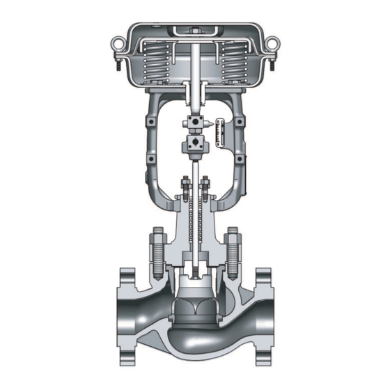
Page 7: Structures
1-3. Structures The structures of typical CV3000 Series control valves are shown is Fig. 1-1 through 1-4. The valve body is connected to the bonnet with stud bolts and nuts. A gasket is (two gaskets are) provided at the connection section to seal against the internal fluid or to let the valve body make up a pressure vessel. -
Page 8: Nameplate
The nameplate indicate also the product number (PROD.NO.) of the control valve. Please mention this number also when consulting your Azbil Corporation agent for replacement of parts or other modification of the control valve. -
Page 9: Chapter 2. Installation
Chapter 2. Installation 2-1. Maximum lifting loads of eyebolts The diaphragm case has a pair of lifting eyebolts. These eyebolts primarily are for lifting the actuator alone. When using the eyebolts for other purposes (such as lifting an actuator bed to its valve body or other components), note that the allowable maximum lifting loads of the eyebolts are as shown in the following table. -
Page 10: Item To Be Checked After Installation And Before Starting Operation
2-3. Item to be checked after installation and before starting operation (1) Check that there is no leak from air piping. (2) Check that the bolts and nuts of the diaphragm case are not loose. Standard tightening torques are as follows: (3) Tighten the packing flange nuts to prevent leak from the gland packing section. - Page 11 Squeeze Lubricator Screw Handwheel G1/2 Figure 2-3 Lubricator for High Pressure Valve Figure 2-2 Lubricator (Class 600 or under) (Class 600 or higher) Lubricating Procedure (a) prepare grease of the type indicated on the nameplate. (b) Tightly close the lubricator handwheel. (c) Remove the squeeze screw, apply grease, and set the squeeze screw.
-
Page 12: Chapter 3. Inspection And Maintenance
Chapter 3. Inspection and Maintenance Inspect and service the actuator as follows: (1) Tightening the gland: Tighten the gland once in every 6 months or thereabout. The tightening procedure is as given in Section 2-3-(3). (2) Lubricating the gland: Lubricating the gland once in every 6 months or thereabout. The lubricating procedure is as given in Section 2-3-(4). -
Page 13: Chapter 4. Disassembly And Assembly
Chapter 4. Disassembly and Assembly This chapter covers the disassembly and assembly procedures of the actuator for its overhaul or modification. 4-1. Detaching actuator from valve body See Fig. 4-3. (1) Apply to the actuator an air pressure so that the valve position pointer is at a point of 10% - 20% above the fully closed point. - Page 14 Assembly Procedure (1) For an integral-type cage valve, put a spiral gasket in the valve body. For a splittype cage valve, securely fix the seated ring into the valve body with threads, using the special tools. (Apply lubricant “Neverseize” to the gasket, except those of the oil-inhibited valves. For the tightening torque of HPC, see Table 4-1.) (2) Put the gasket (2) in the valve body.
- Page 15 Table 4-2 HCB/HCU/HCN Seated Ring Tightening Torques Size (in.) Torque (N.m{kgf-cm}) 650 {6,500} 800 {8,000} 1,200 {12,000} 1,500 {15,000} Table 4-3 Tightening Torques of Bonnet Stud Bolts Bolt Torque (N.m{kgf-cm}) 60 {600} 100 {1,000} 150 {1,500} 200 {2,000} 250 {2,500} 350 {3,500} 500 {5,000} 660 {6,600}...
- Page 16 Packing Flange Nut Packing Flange Packing Follower Stud Bolt Gland Packing Hex Nut (1) Bonnet Gasket (1) Stud Bolt Combination of Trim Parts Va lve Body Combination of Trim Parts Valve Stem Piston Ring Piston Ring Valve Plug Cage Gasket (2) Spiral Gasket Model HCB...
- Page 17 Lubricator Extension Bonnet Combination of Trim Parts Combination of Trim Parts Gasket (2) Seat Ring Model HCB Model HCN Model HCB Model HCU Split Cage Type Split Cage Type Split Cage Type Plug with Piston Ring Figure 4-1-2 High Temperature Type (Extended Bonnet Type) Figure 4-1 Model HCB, HCN, HCU Control Valves...
- Page 18 Figure 4-2 Model HPC Control Valves...
-
Page 19: Disassembly And Assembly Of Actuator
4-3. Disassembly and assembly of actuator Normally the actuator requires no adjustment. However, it should be disassembled and assembled when installing it on a valve body, when modifying its specifications, or when replacing damaged parts. The disassembly and assembly procedure of the actuator for such purposes are covered in Sections 4-4 and 4-5. -
Page 20: Disassembly And Assembly Of Model Psa 1
Notes for Disassembly (1) The nuts for the eyebolts are made of stainless steel. Discriminate these nuts from other nuts when assembling the diaphragm case. (2) It is recommendable to make locating marks on the top and bottom diaphragm cases before disassembly. - Page 21 Rain Cap Eye Bolt Diaphragm Case (Top) Hex Bolt Diaphragm Case (Top) Eye Bolt Hex Nut Was her Hex Bolt Spring Plate Hex Nut Was her Spring Diaphragm Retainer Diaphragm Plate Diaphragm Diaphragm Diaphragm Plate Stopper Part Diaphragm Retainer Spring Spring Plate Hex Bolt Diaphragm...
- Page 22 Assembly Before assembly, check the parts for scratches, damage, deformation, peeling paint or any other abnormalities. To assemble the actuator, proceed as follows: A. Direct action models (1) Secure the diaphragm case (bottom) with the four bolts to the yoke. At the same time, set the air vent hole as in Figure 4-6.
- Page 23 B. Revers action models (1) Secure the bottom diaphragm case with the four bolts to the yoke. At the same time, set the air pipe connection port in the location shown in the Figure 4-7. (2) Insert the actuator rod (with diaphragm connected) into the bushing. Be careful to prevent the bushing 's inside surface or dust seal from being damaged by the threaded section of the rod.
- Page 24 Direct Action type Reverse Action type Figure 4-8 Bolts and Nuts of Actuator Table 4-4 Tihtening Torques of Bolts and Nuts of Actuator Unit:(N.m{kgf-cm}) Materials PSA1 SK5 S45C 45-70 {460-710} S30C 35-50 {360-510} SUS304 15-20 {150-200} SUS304 10-15 {100-150} Note: Install the rain cap on the reverse actuator as follows. Drive the cap into the diaphragm case until the shoulder (brim) of the cap is brought into contact with the diaphragm case, then drive the cap further into the diaphragm case by half a turn.
- Page 25 Direct Action type Reverse Action type Figure 4-9 Model PSA Actuator Parts Name Material Parts Name Material S45C, SUS301 Hex Bolt SUS304 Diaphragm Case (Top) SAPH400 Hex Nut SUS304 Diaphragm EPDM, Polyimide Spring Plate SUS304CP Eye Bolt SUS304 Hex Bolt S30C Hex Nut SUS304...
-
Page 26: Disassembly And Assembly Of Model Ha2, Ha3, Or Ha4 Actuator
4-5. Disassembly and assembly of model HA2, HA3, or HA4 actuator Disassembly Procedure (a) Direct Action Type (1) Disconnect the air piping and detach the accessories from the actuator. (2) Remove the stem connector, pointer and lock nut. (See Fig.4-17) (3) Remove the clamping-bolts (except the pair of eyebolts) of the diaphragm case. - Page 27 (b) Reverse Action Type (1) Disconnect the air piping and detach other external items from the actuator. (2) Remove the stem connector, pointer and lock nut. (See Fig. 4-17) (3) Remove the clamping-bolts (except the pair of eyebolts) of the diaphragm case. (4) Loosen evenly and alternately the pair of eyebolts.
- Page 28 Assembly Procedure Before assembly, check the parts for scrapes, damage, deformation, peeling off of paint, and other abnormality. To assemble the actuator, proceed as followes: (a) Direct Action Type (1) Fix the bottom diaphragm case and yoke with the bolts. (For models HA2D and HA3D, install the diaphragm case and spring plate together.) (2) Install the springs on the spring plate.
- Page 29 (b) Reverse Action Type (1) Fix the bottom diaphragm case and yoke with the bolts. (2) Insert the actuator rod (to which the diaphragm is connected) into the hushing, exercising care not to damage the bushing inside surface or dust seal with the thread section of the rod.
- Page 30 Direct Action type Reverse Action type Figure 4-16 Bolts and Nuts of Actuator Table 4-5 Tightening Torques of Bolts and Nuts of Actuator Unit:(N.m{kgf-cm}) Materials For HA2 For HA3 For HA4 S45C/SUS301 37 {370} 100 {1,000} 310 {3,170} S30C 42 {420} 100 {1,000} 360 {3,360} SUS304...
- Page 31 Direct Action Type (Model HA3D) Reverse Action Type (HA3R) Parts Name Material Parts Name Material S45C, SUS301 Spring SWOSM-B Diaphragm Case (Top) SAPH370 Hex Bolt SUS304 Diaphragm EPDM+Nylon66 Hex Nut SUS304 Eye Bolt SUS304 Spring Plate SPCC Hex Nut SUS304 Hex Bolt S30C Diaphragm Case (Bottom) SAPH370...
-
Page 32: Disassembly And Assembly Of Model Psa6 Actuator
4-6. Disassembly and assembly of model PSA6 actuator Structure This actuator is comprised of a cylinder, spring unit, lift stopper, spring retainer, hex stay, yoke, manual handwheel and a single action positioner. For an external view of the a actuator, refer to Figure 4-18 "Exterior of PSA6R". Figure 4-18 Exterior of PSA6R Assembly on valve body The Assembling nuts are integral to the valve body connect the yoke and valve body. - Page 33 CAUTION In operation and handling • W hen automatically operating an actuator with the manual handwheel, verify that the AUTO/MANUAL switchover pin is inserted into the pin holder, the chain is engaged with the handwheel and the indicator is in AUTO position starting operation.
- Page 34 Procedure Step Procedure Pull AUTO/MANUAL switchover pin out of its holder and disengage the chain, that connects the handwheel with the wheel. Check the label on the handwheel and turn the handle in the shut direction and lower the slide screw. Align the round holes of the slide screw and the actuator rod, and then insert pin.
-
Page 35: Disassembly And Assembly Actuator
4-7. Disassembly and assembly actuator Disassembly and assembly procedures are described herein. Refer to them for periodic maintenace or if a malfunction occurs which may call for the disassembly or assembly of the actuator. Before disassembly (1) Only the nuts for the eyebolts are made of stainless steel. Keep these nuts separate from other nuts when disassembling the diaphragm case. - Page 36 Disassembly of actuator <Disassembly procedure> Disassembly procedure of actuator is described herein. Refer to Figure 4-22 and 4-23 or Table 4-6 for the information. 1. Marking and protection Step Procedure Match the mark of the spring retainer No.10 at the top of actuator, lift stopper No.13, cylinder No.14 and cylinder assembling yoke boss.
- Page 37 5. Removing slide screw and cylinder Step Procedure Turn slide screw No.32 by hand and extract from the bottom. Loosen hex head bolts No.6 (four bolts) which fasten the cylinder and manual handwheel and remove. Lift cylinder straight up and remove. 6.
- Page 38 Spring Unit Figure 4-22 PSA6R...
- Page 39 Spring Unit Figure 4-23...
- Page 40 Table 4-6 Parts reference list Parts description Parts description Parts description Eye Nut Slide Screw Hex Nut Bushing O-Ring Spring Washer Dust Seal Piston Hex Stay(Long) Tape Liner Spring Washer O-Ring Slide Screw Rotation Stopper Locking Nut Hex Bolt Hex Bolt Stopper Seal Washer Seal Washer...
- Page 41 Disassembling spring unit <disassembly procedure> The disassembly procedure of spring unit is described herein. See Figure 4-24 for reference on part names. Disassembly is not required if only the piston's sealing parts (tape liner, O-ring) are to be replaced. 1. Removing spring unit Step Procedure Loosen hex nuts No.10 (four at the top) and remove.
- Page 42 Assembling actuator <Cautions during assembly> ƒ Refer to the chapter of inspection items during disassembly and verify that no abnormality is found on the parts. If any are found, replace or repair as required. ƒ The O-ring of sliding parts should always be replaced at the time of periodic disassembly. Whenever the O-ring on the fixed part is deformed, damaged, or scarred during disassembly, replace it.
- Page 43 2. Assembly of piston unit, lift stopper and spring retainer Step Procedure Install eyebolts into threaded holes (M12*2) at the top of spring retainer No.9 on the piston unit, suspend with crane and lift upward. While suspended, assemble lubricated O-ring No.15 and wear ring No.14 on piston No.3.
- Page 44 Tightening torques of actuator assembly The table below lists the tightening torques for actuator assembly. Refer to Fig. 4-26. Table 4-7 Tightening torque of bolt and nuts of actuator Key No. Size Tightening torque (N.m{kgf-cm}) 45-70 {450-700} 160-215 {1600-2200} 215-275 {2200-2800} 45-70 {450-700} 35-50 {350-500} Figure 4-26 Tightening torque of actuator thread...
-
Page 45: Chapter 5. Adjustment
Chapter 5. Adjustment As a general rule the diaphragm type control Valves require no adjustment. However, when coupling an actuator to a valve body after removing the actuator for overhaul or other purposes, adjustment of travel (stroke) is necessary. For this adjustment, refer to Fig. 4-3, Fig. 5-1 and proceed as follows: (1) Fix the actuator to the valve body by securely tightening the yoke clamping-nut (use a chisel and a hammer). - Page 46 Actuator Stem Set at maximum or minimum value of spring range (for direct or reverse action) by moving actuator stem in this direction. Valve Yoke Stem Yoke-Clamping-Nut Figure 5-1...
-
Page 47: Change Of Actuator
Chapter 6. Direct / Reverse Action Type Conversion and Spring Range Change of Actuator 6-1. Direct / Reverse action change As a general rule it is most recommendable to prepare separately the direct type and reverse type of actuators and not to convert actuators into different types. However, when it has become unavoidable to convert actuators into other types, conversions may be done by using the parts mentioned below (Table 6-1 and Table 6-2). - Page 48 HA3D → HA3R For stroke For stroke For stroke Part name Q'ty 14.3 mm 25 mm, 38 mm 38 mm Seal washers 82521069-102 82521069-102 82521069-102 Rod packing 82521067-102 82521067-102 82521067-102 82521431-202 (25 mm) Rod unit 82521431-201 82521431-204 82521431-203 (38 mm) Rain cap 82553334-101 82553334-101...
- Page 49 Table 6-2 To Convert the Reverse Action Type into the Direct Action Type PSA1R → PSA1D Part name Q'ty 82559229-102 14.3 mm Rod unite 82559229-101 25 mm 82559228-102 14.3 mm 82559228-101 25 mm Seal washer 82521069-101 Rod packing 82521067-102 Rain cap 82553334-101 "O"...
- Page 50 HA3R → HA3D For stroke For stroke For stroke Part name Q'ty 14.3 mm 25 mm, 38 mm 50 mm Seal washers (-2) 82521069-102 82521069-102 82521069-102 Rod packing (-1) 82521067-102 82521067-102 82521067-102 82521428-102 (25 mm) Rod unit 82521428-101 82521428-104 82521428-103 (38 mm) 82521431-202 (25 mm) (-1) 82521431-201...
-
Page 51: Stroke And Range Spring Change
6-2. Stroke and range spring change As a general rule it is most recommendable to prepare separate actuators for diffent strokes and spring ranges to avoid modifications. However, modifications can be done by using the parts mentioned below. Of Models HA2 and HA3, there are two different diameters of bonnet connection sections. For these models, note the following: Of Model HA2, modification for change between read stroke of 14.3 or 25 mm and that of 38 mm cannot be done. - Page 52 Actuator Part name Q'ty For stroke 25 mm For stroke 38 mm Scale plate 80225032-464 82554022-103 20-98 {0.2 -0.1} 82521206-101 82521206-103 Spring 80-240 {0.8-2.4} 82521206-102 82521209-101 R (Reverse action) 82521431-202 82521431-203 unit D (Direct action) 82521428-102 82521428-103 Actuator For stroke For stroke For stroke For stroke...
- Page 53 Color Codes and Dimensions of the Springs of Model HA Actuators The color codes and dimensions of the springs of Model HA Actuators are as shown in the following table. The color codes may help you confirm springs when disassembling and assembling actuators for modification or other purpose.
-
Page 54: Chapter 7. Instructions For Top Handwheel Of Actuator
Chapter 7. Instructions for Top Handwheel of Actuator 7-1. Model PSA1 actuator 7-1-1. Operating instructions To manually operate the actuator, refer to Fig. 7-1 and Fig. 7-2 and proceed as follows: (1) Loosen the lock nut of the handwheel and turn the handwheel in the direction indicated by the corresponding arrowhead mark. - Page 55 Direct Action Type Reverse Action Type Parts Name Parts Name Parts Name Hex Nut Hex Bolt Spring Washer Bushing Truss Screw Washer Dust Seal Scale Plate Handwheel Stem Connector Name Plate Lock Nut Screw Shaft Drive Screw Washer Housing yoke O-Ring Spring Pin Rain Cap...
-
Page 56: Disassembly And Assembly Of Top Handwheel
7-1-2. Disassembly and assembly of top handwheel To disassemble or assemble the top handwheel, refer to Fig. 7-1 through 7-4 and proceed as described in this section. For disassembly work, keep the actuator in the vertical attitude. (a) Direct Action Type (1) Disconnect the air piping. - Page 57 Figure 7-2 Model PSA1 Direct Action Type Figure 7-3 Model PSA1 Reverse Action Type...
-
Page 58: Model Ha2, Ha3, Or Ha4 Actuator
7-2. Model HA2, HA3, or HA4 actuator 7-2-1. Operating instructions To manually operate the actuator, refer to 'Fig. 7-4 through Fig. 7-7 and proceed as follows: (1) First, loosen the lock nut (which has a bar-shape handle and which locks the handwheel, and turn the handwheel in the direction indicated by the corresponding arrowhead mark. - Page 59 Parts Name Hex Nut Washer Handwheel Screw Shaft Lock Nut O-Ring C type Retaining Ring Diaphragm Case(Top) Eye Bolt Hex Nut Diaphragm Diaphragm Case(Bottom) Bushing Bearing Dust Seal Pointer Yoke Stem Connector Hex Bolt Housing Bearing Spring Retainer O-Ring Seal Washer Hex Bolt Diaphragm Retainer Stopper...
- Page 60 Parts Name Hex Nut Washer Handwheel Screw Shaft Lock Nut Bearing Case Rain Cap Diaphragm Case(Top) Eye Bolt Hex Nut Diaphragm Connection Diaphragm Case(Bottom) Stopper Diaphragm Retainer Bearing Bushing Yoke Lock Nut Pointer Stem Connector Hex Bolt Housing Bearing Washer Bearing Cotter Pin Seal Washer...
- Page 61 Parts Name Hex Nut Washer Handwheel Screw Shaft Lock Nut Bearing Case Rain Cap Diaphragm Case(Top) Eye Bolt Hex Nut Diaphragm Diaphragm Case(Bottom) Stopper Connection Diaphragm Retainer Bearing Bushing Yoke Pointer Stem Connector Hex Bolt Housing Bearing Washer Bearing Cotter Pin Seal Washer Hex Bolt Spring...
- Page 62 Parts Name Washer Handwheel Lock Nut Screw Shaft Bearing Case Diaphragm Case(Top) Eyebolt Through Bolt Diaphragm Diaphragm Case(Bottom) Stopper Connector Diaphragm Retainer Bearing Bushing Yoke Pointer Stem Connector Stem Connector Bolt Housing Washer Bearing Bearing Cotter Pin Seal Washer Bolt Coil Spring Setscrew Bolt...
-
Page 63: Disassembly And Assembly Of Top Handwheel
7-2-2. Disassembly and assembly of top handwheel To disassemble or assemble the top handwheel, refer to Fig. 7-4 through 7-9 and proceed as described in this section. For disassembly and assembly work, keep the actuator in the vertical attitude. (a) Direct Action Type (1) Disconnect the air piping. - Page 64 Figure 7-8 Direct Action Type Figure 7-9 Reverse Action Type...
-
Page 65: Chapter 8. Instructions For Side Handwheel Of Actuator
Chapter 8. Instructions for Side Handwheel of Actuator As you turn the handwheel clockwise, the actuator stem moves downward regardless of whether the actuator is of the direct action type or reverse action type. The handwheel bears the ''SHUT' mark to indicate that the valve is closed as the handwheel is tuned clockwise and the "OPEN'' mark to indicate that the valve is made open as the handwheel is tuned counterclockwise. -
Page 66: Disassembly Of Side Assembly Of Side Handwheel
8-3. Disassembly of side assembly of side handwheel Before starting disassembly, check that the pointer is set at the AUTO position. (Refer to Fig. 8-1) (1) Loosen the bolt 6 which connects the levers 2 and then disengage the levers from the pointer. - Page 67 Parts Name Material Housing FC200 Lever SS400 Shaft S20C Bushing SPCC, Bronz, PTFE Bearing S20C Screw SUS304 A–A Pointer SUS304 Collar Hex Bolt SUS304 Hex Bolt SUS304 Bushing SUS304 Spring Washer SWRH62B, SUS304 Handwheel FC200 Washer SPCC Hex Nut SUS304 Handle Lock SPCC Hex Nut...
-
Page 68: Chapter 9. Instructlons For Bellows Sealed Type Of Control Valves
Chapter 9. Instructlons for Bellows Sealed Type of Control Valves The bellows sealed type of control valves differ from other control valves in that the former employ a bellows for seal. This chapter covers primarily the particular items related to the bellows sealed type of control valves. -
Page 69: Structures (Model Hcb Control Valves)
9-1. Structures (Model HCB Control Valves) The structures of Model HCB Control Valves are shown in Fig. 9-1. Hex Nut (2) Bellows Flange Packing Flange Nut Backup Ring Nut (1) Packing Flange Seal Ring Stem Bellows Seat Bellows Assembly Gasket (3) Gasket (4) Hex Nut (3) Extension Bonnet... -
Page 70: Disassembly And Assembly
9-2. Disassembly and assembly (1) Detach the actuator from the valve as described in Section 4.1. (2) Loosen the packing flange nut. (3) Loosen the hex nut (1) of the bonnet, using the wrench. (4) Raise the bonnet and remove the gasket (3). Note: When raising the bonnet, press down the stem so that it will not come up together with the bonnet. -
Page 71: Chapter 10. Troubleshooting
This chapter covers the symptoms, causes and remedies of most probable types of troubles. Parts may be required to be replaced depending on the type of trouble. For further troubles, please order your Azbil Corporation agent for repair. Table 10-1 Troubleshooting... - Page 72 Symptom Cause and Remedy • Air leak at actuator section. Even when valve plug • F or trial, apply the air supply pressure or atmospheric is in closed position, large flow leaks to pressure to the actuator. (Check the air supply source and downstream side. positioner.) • C heck whether the valve plug is actually the closed position or not. (Check the valve plug lift) • Check the plug seat ring for corrosion and erosion.
-
Page 73: Chapter 11. Recommended Spare Parts
Chapter 11. Recommended Spare Parts It is most recommendable to replace the following parts when servicing the control valve. • Valve Body Be sure to replace the following parts with fresh ones whenever the valve body is disassembled: • Gland packing • Gaskets • Actuator Replace the following Parts at every 5 years or thereabout. - Page 75 Warranty period and warranty scope 1.1 Warranty period Azbil Corporation's products shall be warranted for one (1) year from the date of your purchase of the said products or the delivery of the said products to a place designated by you.
- Page 76 Azbil Corporation's products every 5 to 10 years unless otherwise specified in specifications or instruction manuals.
- Page 78 Document Number: OM2-8113-0202 Dcument Name: CV3000 series Control Valves Model: HCB,HCU,HCN,HPC User's Manual Date: 9th Edition: June 2012 10th Edition: Nov. 2014 Issued/Edited by:...
Need help?
Do you have a question about the CV3000 Series and is the answer not in the manual?
Questions and answers