
Related Manuals for Azbil AGVB


Summary of Contents for Azbil AGVB
- Page 1 CM2-AGV200-2001 Top-Guided Single-Seated Control Valve Top-Guided Single-Seated Control Valve Model AGVB/AGVM Model AGVB/AGVM User’s Manual User’s Manual...
- Page 2 In no event shall Azbil Corporation be liable to anyone for any indirect, special or consequential damages. This information and specifications in this document are subject to change without notice.
- Page 3 With the improved leakage performance of the valve seat, instrumentation costs can be reduced significantly. Azbil is proud to provide high reliability and quality based on its abundant achievements and know-how in the field.
- Page 4 „ Precautions for Storage Observe the following precautions in order to store the purchased valve properly. • If the valve is packed in a cardboard box, store it indoors at room temperature and humidity. • A valve packed in a wooden crate should also generally be stored indoors at room temperature and humidity.
- Page 5 Safety Precautions „ Symbols Safety precautions are for ensuring the safe and correct use of this product, and for preventing injury to the operator and other people or damage to property. Be sure to observe these safety precautions. The safety precautions described in this manual are indicated by various icons. Their meaning is explained below.
- Page 6 Notes for Safe Operation WARNING Before starting to work, check that the pressure in the pipes has dropped to atmospheric pressure. If fluid spews out, injury may result. CAUTION Do not stand on the device or use it as a step. There is a risk of falling. Do not touch the device unnecessarily while it is operating.
- Page 7 Handling Precautions „ Installation Precautions WARNING If the rated pressure or standards for connection are ignored when this device is used, damage to the product or leakage may cause a serious accident. When connecting the valve to the piping, do not put your hand or foot under the valve or between flanges.
- Page 8 CAUTION After installation, check that the pipes are still properly aligned. Misalignment may cause fluid leakage from pipe connections. Install the butterfly valve with the valve (blade or disk) fully closed. Otherwise the valve might be damaged. If the eyebolts (eyenuts) attached to the actuator are used to hoist the valve, make sure that the weight does not exceed the limit specified in the user's manual.
- Page 9 Handling Precautions • Avoid installing the valve where it will be subject to vibration or other external forces that may affect its performance. • Protective covers are attached to the flanges to protect the gasket-contacting surfaces and to prevent foreign matter from entering the valve. When installing the valve, remove the covers.
- Page 10 „ Precautions for Air Supply Piping and Electrical Work CAUTION For air supply, use pipes with an appropriate internal diameter so that pressure will not drop while the valve is operating. Failure to do so may result in poor valve performance. Wiring work should be carried out only by qualified technicians following local electrotechnical standards.
- Page 11 „ Precautions for Assembly and Disassembly WARNING Before starting work, clean the inside of the valve, replace any residual gas, etc. Otherwise, the residual fluid may cause an injury. Do not disassemble the pneumatic actuator while supply air pressure is being applied. The compressed air may cause an injury.
- Page 12 Close valve Close valve Open Close pressure pressure Valve Pressure regulator Tighten bolts to speci ed torque Replace the packing and gasket Follow the assembly procedure Packing Gasket...
- Page 13 „ Precautions for Maintenance WARNING If fluid leakage from the valve is found, stay away from the valve until safety can be confirmed. Depending on the properties of the fluid, a serious accident or injury may result. CAUTION Check the gland daily, and tighten the packing if leakage is found. Check valve operation daily, including a visual check for hunting.
-
Page 15: Table Of Contents
Table of Contents Chapter 1. Structure of the Control System ........1-1 1-1. - Page 16 Chapter 7. Disassembly and Reassembly of Model PSA6 Spring Type Piston Cylinder Actuator ..........7-1 7-1.
-
Page 17: Chapter 1. Structure Of The Control System
Air supply AVP300 Fluid Figure 1-1. Control System This manual contains operating instructions for a model AGVB/AGVM top-guided single- seated control valve. For details on positioners, refer to the user’s manuals below. • Pneumatic single-acting valve positioner (model HTP): document No. OM2-8310-0200 •... -
Page 18: Control Valve Structure
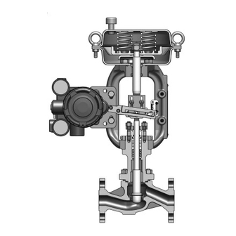
1-2. Control Valve Structure This device is composed of a valve body and an actuator. The valve body consists of a valve, bonnet, valve plug, and other components. The actuator consists of a diaphragm, spring, and other components. Figure 1-2 illustrates the structure of this device. Compressed coil spring Diaphragm... -
Page 19: Specifications Of The Control Valve
1-3. Specifications of the Control Valve Since the control valve contacts the process fluid, its specifications must be appropriate for the process conditions and the purpose of use. The standard specifications for the AGVB and AGVM are described in “Appendix A. Standard Specifications”. -
Page 21: Chapter 2. Installation
Chapter 2. Installation 2-1. Installation Location Please observe the following cautions when selecting the installation site for the control valve. WARNING If the rated pressure or standards for connection are ignored when this device is used, damage to the product or leakage may cause a serious accident. - Page 22 CAUTION Chamfer the edges of the pipe flanges. Sharp edges can cause an injury. Check that the pipes on both sides of the valve are firmly supported. Insufficient support may cause leakage from pipe connections. After installation, check that the pipes are still properly aligned. Misalignment may cause fluid leakage from pipe connections.
- Page 23 Space for maintenance Pipe support The control valve is designed to withstand severe operating conditions. However, in order to achieve its optimal performance, install the valve to a location with the following conditions: • Ambient temperature: -30 to +70 °C •...
-
Page 24: Check Before Installation On The Pipe
2-2. Check before Installation on the Pipe Check the following before installing the AGVB control valve on the piping. 1. The specifications printed on the name plate are appropriate for the use. 2. There is no damage to the valve (including the actuator and auxiliary equipment). -
Page 25: Installation On The Pipe
2-3. Installation on the Pipe 2-3-1. Standard Installation Example Figure 2-2 illustrates standard installation. Gasket Bolt Pipe Figure 2-2. Installation on the pipe 2-3-2. Installation method Step Procedure Check that the flow direction of the process fluid is the same as the direction indicated on the control valve. -
Page 26: Air Supply Connection
2-4. Air supply connection See the user’s manual for your positioner. • Pneumatic single-acting valve positioner (model HTP): document No. OM2-8310-0200 • Pneumatic single-acting valve positioner (model VPE): document No. OM2-8310-0410 • Smart valve positioner (model AVP300/301/302 (integral type)): document No. CM2-AVP300-2001 •... -
Page 27: Chapter 3. Operation
Chapter 3. Operation 3-1. Trial-Run Inspection and Adjustment (1) Operation test Send a 4–20 mA DC or other dummy signal (0 to 100 %) to the valve positioner or actuator to check that the rated travel is achieved. Refer to Table 3-1 and if the allowable value is exceeded, adjust the valve positioner. -
Page 28: Troubleshooting
3-3. Troubleshooting Problems that might occur during operation are described in Table 3-2. Take necessary measures such as replacing parts, depending on the circumstances Table 3-2. Control valve problem causes and countermeasures Phenomenon Cause Countermeasure • Reduce the differential pressure between the The valve hunts near the The valve capacity is too large. - Page 29 Table 3-2. Control valve problem causes and countermeasures Phenomenon Cause Countermeasure • Check the signal pipe (especially the fitting) Supply air pressure is Leakage from the signal pipe normal, but signal pressure • Replace the diaphragm. Leakage from the diaphragm or does not increase damage to the diaphragm •...
- Page 30 Table 3-2. Control valve problem causes and countermeasures Phenomenon Cause Countermeasure Looseness of the gland packing or bolts • Tighten the gland packing or bolts. Fluid leaks from the gland packing. • Replenish the grease. Grease depleted (for graphite yarn packing) •...
-
Page 31: Chapter 4. Maintenance
Chapter 4. Maintenance 4-1. Inspection of the Control Valve Check the control valve in accordance with the following instructions in order to maintain proper performance, prevent accidents, and detect problems early. Daily inspection and periodic inspection (overhaul) must be carried out. When inspecting the valve, be sure to observe the instructions below. - Page 32 WARNING If fluid leakage from the valve is found, stay away from the valve until safety can be confirmed. Depending on the properties of the fluid, a serious accident or injury may result. CAUTION Check the gland daily for leakage. Check valve operation daily for hunting.
-
Page 33: Periodic Inspection
4-1-2. Periodic Inspection Disassemble the control valve once every two or three years. Replace consumables and repair or replace any parts that have deteriorated. When disassembling the valve, be sure to observe the instructions in “Chapter 5. Disassembly and Reassembly of the Control Valve”. Recording inspection results Recording the results of periodic inspection on the following items is recommended. -
Page 34: Removing The Control Valve
(9) Damage or corrosion on the gasket-contacting surface Check the gasket-contacting surface of the valve and bonnet for damage or deterioration, such as corrosion that will cause a leak. If a problem is found, repair, re-machine, or replace the part. CAUTION Dispose of old parts that were replaced during valve disassembly or main- tenance as industrial waste. - Page 35 CAUTION Wiring work should be carried out only by qualified technicians following local electrotechnical standards. Avoid doing wiring work on a rainy day or in high humidity. Moisture inside the connectors or the terminal box may cause a short-circuit or rust. A packing (gasket) is attached to the cap of auxiliary equipment such as positioners.
-
Page 37: Chapter 5. Disassembly And Reassembly Of The Control Valve
Chapter 5. Disassembly and Reassembly of the Control Valve This section gives instructions on disassembly and reassembly of the control valve. If you need to disassemble and reassemble the valve for periodic inspection, troubleshooting, or other circumstances, refer to the instructions. 5-1. -
Page 38: Procedure For Changing The Mounting Orientation Of The Actuator
Step Procedure • Removing the actuator from the valve body With the hammer and chisel, loosen and remove the nuts that hold the yoke. Lift and remove the actuator from the valve body. Note: Before disassembling a control valve that is installed on the piping, be sure to shut off the fluid in the piping and release the process pressure. - Page 39 Hex nut Matching marks Stem connector Yoke tightening nut Figure 5-1. Removal of the actuator from the valve body and reassembly...
-
Page 40: Disassembling The Valve Body
5-4. Disassembling the Valve Body Precautions for disassembly • Disassemble the valve body on a rag, etc., to avoid damaging the valve. • After disassembling the valve body, protect the gasket-contacting surfaces, the valve plug- contacting surfaces, sliding areas, seat ring, etc., with a rag or the like. CAUTION Dispose of old parts that were replaced during valve disassembly or main- tenance as industrial waste. - Page 41 Hex nut Packing ange Stud bolt Bonnet Hex nut O-ring* O-ring* Packing Packing follower follower O-ring* Stud bolt O-ring* Packing holder V-shaped PTFE yarn PTFE packing packing Guide bushing Packing retainer Valve material: Valve material: Spacer SCPH2 SCS13A, SCS14A Spring Packing ring Gasket PTFE yarn packing...
- Page 42 Hex nut Packing ange Stud bolt Hex nut Bonnet O-ring* O-ring* Stud bolt Packing Packing follower follower O-ring* O-ring* Packing holder Guide bushing V-shaped PTFE yarn PTFE packing packing Valve material: Valve material: SCPH2 SCS13A, SCS14A Packing retainer Spacer Spring Gasket Packing ring PTFE yarn packing...
- Page 43 Hex nut Packing ange Stud bolt Hex nut Bonnet Stud bolt O-ring* O-ring* Packing Packing follower follower O-ring* O-ring* Guide bushing Packing holder V-shaped PTFE PTFE yarn packing Valve material: Valve material: packing SCPH2 SCS13A, SCS14A Packing retainer Spacer Spring Packing ring Gasket PTFE yarn packing...
-
Page 44: Reassembling The Valve Body
(2) Removing the trim After removing the valve plug, remove the seat ring with the special wrench for the seat ring. (3) Taking out the gland parts Take out the gland parts with a pipe, etc. Take notes of the type, quantity, order, etc., of parts such as the packing and spacers in order to facilitate reassembly. - Page 45 Table 5-1. Seat ring tightening torque Unit: N·m Connection diameter (inches) Seat ring tightening torque 1/2, 3/4, 1 140 to 150 1-1/2, 2 210 to 230 2-1/2, 3 340 to 380 590 to 650 Table 5-2. Bonnet hex nut tightening torque Unit: N·m Connection diameter (inches) Bonnet hex nut...
- Page 46 (3) Assembling the valve plug and bonnet Step Procedure Apply an agent for preventing galling* to a new gasket and set the gasket on the valve in place. Insert the valve plug into the bonnet, then place the bonnet on the valve. Be sure to align the matching marks, which were placed before disassembly, in order to set the bonnet in the right position.
- Page 47 Figure 5-2 to Figure 5-4, which illustrates the structure of the gland. If Azbil’s low-emission gland packing system is used, refer to Chapter 8. Insert the parts all the way to the bottom with a pipe, etc. If PTFE yarn packing is used, insert it with the cut part of the packing shifted by 180°.
- Page 48 5-12...
-
Page 49: Chapter 6. Disassembly And Reassembly Of Model Psa Actuator
Chapter 6. Disassembly and Reassembly of Model PSA Actuator 6-1. Disassembly of the Actuator Precautions • All the nuts for the eyebolts are stainless steel. Do not mix them up with other nuts. • Place the removed parts in a clean place. •... - Page 50 (2) Removing bolts and nuts from the diaphragm case Step Procedure Loosen and remove the hex nuts and bolts, except for the eyebolt nuts, from the dia- phragm case. Loosen the two eyebolt nuts evenly and remove them. CAUTION For disassembly of an actuator that contains springs, follow the disassembly procedure when removing bolts, nuts, etc.
- Page 51 Eye bolt Eye bolt Diaphragm case (top) Diaphragm case (top) Bolt Bolt Washer Washer Diaphragm retainer Diaphragm retainer Diaphragm Diaphragm Diaphragm plate Diaphragm plate Stopper part Spring Spring plate Spring Bolt Spring plate Bolt Diaphragm case Diaphragm case (bottom) (bottom) Bushing Bushing Dust seal...
- Page 52 Rain cap Rain cap Diaphragm case (top) Diaphragm case (top) Eye bolt Eye bolt Bolt Bolt Spring plate Spring plate Spring Spring Washer Washer Stopper Stopper Diaphragm plate Diaphragm plate Diaphragm Diaphragm Diaphragm retainer Diaphragm retainer Bolt Seal washer Bolt Diaphragm case Seal washer (bottom)
- Page 53 (29) Single-tongued washer (2) Upper diaphragm case (28) Cap (29) Single-tongued washer (13) Diaphragm holder(1) Locknut (1) Locknut (4) Eyebolt (18) Spring plate (3) Diaphragm (14) Diaphragm plate (5) Hex nut (15) Spring (4) Eyebolt (6) Mounting bolt (16) Hex bolt (16) Hex bolt (17) Hex nut (15) Spring...
-
Page 54: Reassembly Of Model Psa Actuator
6-2. Reassembly of Model PSA Actuator Precautions • Check that there is no problem with the parts, referring to the checklist in "4-1-2. Periodic Inspection". If any damage is found, repair or replace the parts as needed. • Always use a new sealing washer, dust seal, and rod seal. •... - Page 55 Figure 6-6. Threaded parts to tighten (on PSA1-4 actuators) Table 6-1. Tightening torque for the actuator Unit: N·m Key No. Material PSA1, PSA2 PSA3 PSA4 S45C, SK5 45 to 70 151 to 169 151 to 169 S30C 35 to 50 90 to 120 90 to 120 SUS304...
- Page 56 Diaphragm plate stopper Eyebolt Air pipe connection port / air vent hole (upper and lower diaphragm cases) Figure 6-8. Direct action (PSA2D) Diaphragm plate Eyebolt Air vent hole (upper diaphragm case) Air pipe connection port (lower diaphragm case) Figure 6-9. Direct action (PSA3D) Diaphragm plate Air pipe connection port (upper diaphragm case)
- Page 57 Diaphragm plate stopper Air vent hole (upper diaphragm case) Eyebolt Air pipe connection port (lower diaphragm case) Figure 6-11. Reverse action (PSA1R) Diaphragm plate stopper Eyebolt Air vent hole (upper diaphragm case) Air pipe connection port (lower diaphragm case) Figure 6-12. Reverse action (PSA2R) Diaphragm plate Air vent hole (upper diaphragm case)
- Page 58 Diaphragm plate Air vent hole (upper diaphragm case) Eyebolt Air pipe connection port (lower diaphragm case) Figure 6-14. Reverse action (PSA4R) (4) Mounting the diaphragm unit and springs • For direct-action actuators Step Procedure Place the spring plate so that springs can be set in the diaphragm case in the manner illustrated in Figure 6-7 to Figure 6-10, and then attach the springs to the spring plate.
- Page 59 (5) Mounting the upper diaphragm case Step Procedure Set the upper diaphragm case such that the air pipe connection port is in the position indicated in Figure 6-7 to Figure 6-10 (for direct operation models) or the air vent hole is in the position indicated in Figure 6-11 to Figure 6-14 (for reverse opera- tion models).
-
Page 60: Mounting The Actuator On The Valve Body
6-3. Mounting the Actuator on the Valve Body Precautions For a side handwheel–equipped actuator, attach the side handwheel to the actuator first, and then mount the actuator on the valve. Assembly procedure In addition to the following instructions, refer to Figure 6-15. -
Page 61: Removing The Side Handwheel From The Actuator
(3) Attaching the accessories Attach the accessories in their original position. (4) Inspection after reassembly • Send the specified control signals and air pressure to the positioner or the actuator. Check the air pipes and their joints for leakage. • Change the control signal to check if the valve operates properly in accordance with the signal. - Page 62 (27)Rotation stopper (26)Connector (28)Pan-head screw with captive spring washer (3)Shaft holder (4)Round bushing (5)Small bearing (25)Lever drive nut (23)Spring washer (8)Shaft (24)Hex bolt (9)Large bearing (19)Flat washer (20)Spring washer (10)Round bushing (21)Hex nut (17)Bushing (1)Side handwheel main unit (29)Round bushing (6)Pointer (22)Cotter pin (7)Pan-head screw...
-
Page 63: Disassembly Of The Side Handwheel
6-5. Disassembly of the Side Handwheel Disassembly procedure Check the size of the actuator and disassemble the side handwheel, referring to Figure 6-15. Step Procedure Check that the pointer on the side handwheel main unit is in the AUTO position. Remove the side handwheel from the actuator. -
Page 64: Mounting The Side Handwheel On The Psa Actuator
6-7. Mounting the Side Handwheel on the PSA Actuator Step Procedure Turn the handwheel so that the pointer on the lever drive nut indicates AUTO. Remove the stem connector from the actuator, screw the connector onto the rod, and fasten it with the rotation stopper. Loosen the bolts and nuts on the levers to widen the space between the levers. -
Page 65: Piston Cylinder Actuator
Chapter 7. Disassembly and Reassembly of Model PSA6 Spring Type Piston Cylinder Actuator 7-1. Overview Structure This actuator consists of a cylinder, a spring unit, a lift stopper, a spring holder, hex staybolts, a yoke, a handwheel, and a single-acting positioner. For an external view of the actuator, refer to “Figure 7-1. - Page 66 Calibration This actuator does not need calibration. When connecting the valve stem of the valve body and the actuator rod with the stem connector, adjust so that the valve plug contacts the seat ring when the valve is fully closed. Next, loosen the screws on the actuator scale and position the scale so that the pointer indicates the correct position in accordance with the valve stroke.
-
Page 67: Auto/Manual Switching Method
7-2. Auto/Manual Switching Method Refer to “Figure 7-2. Auto/manual switching mechanism”. For a handwheel-equipped actuator, automatic operation that uses input signals and manual operation that uses the handwheel can be switched. Auto/manual can be switched at any valve travel during operation. Auto/manual switching pin (auto position) Chain... - Page 68 Step Procedure Pull the auto/manual switching pin out of its holder, and disengage the chain that holds the handwheel. Check “Figure 7-3. Operation instruction label”on the handwheel, and turn the handwheel in the SHUT direction to lower the slide screw. Align the round hole of the slide screw with that of the actuator rod, and insert the switching pin all the way, and then turn the pin to fix it.
-
Page 69: Disassembly And Reassembly Of The Actuator
7-3. Disassembly and Reassembly of the Actuator This section gives instructions on disassembly and reassembly of the actuator. If you need to disassemble and reassemble the valve for periodic inspection, troubleshooting, or other circumstances, refer to the instructions. 7-3-1. Disassembly of the actuator Disassembly procedure This section describes the procedure for disassembling the actuator. - Page 70 (5) Removing the slide screw and cylinder Step Procedure Turn and pull out the slide screw (No. 34) by hand from the bottom. Loosen and remove the four hex bolts (No. 12) that connect the cylinder (No. 21) and the handwheel. Lift the cylinder (No.
- Page 71 (18) (10) (22) (19) (21) (31) (20) (32) (33) (32) (30) (11) (35) (29) (12) (48) (42) (47) (40) (41) (36) (46) (45) (40) (13) (44) (43) (14) (25) (37) (47) (38) (39) (34) (50) (51) (49) (15) (28) (27) (26) Figure 7-5.
- Page 72 Table 7-1. Part name Part name (52) Eyenut Worm wheel (53) Hex nut Slide screw Spring washer Lock pin (59) Long hex staybolt Handwheel O-ring Operation instruction label Piston unit Spring washer Tape liner Locknut O-ring Single-column angular bearing (55) Short hex staybolt Worm shaft...
-
Page 73: Disassembly Of The Spring Unit
7-3-2. Disassembly of the Spring Unit Disassembly procedure This section describes the procedure for disassembling the spring unit. Figure 7-6 Disassembly is not necessary when only the piston sealing parts (tape liner, O-ring) are replaced. (1) Removing the spring Step Procedure Loosen and remove the upper four hex nuts (No. -
Page 74: Reassembly Of The Actuator
7-3-3. Reassembly of the Actuator Precautions • Check that there is no problem with the parts, referring to the checklist in “4-1-2. Periodic Inspection” If a problem is found, repair or replace the part as needed. • The O-ring on the sliding parts should always be replaced at the time of periodic disassembly. - Page 75 (2) Mounting the piston unit, lift stopper, and spring holder Step Procedure Screw eyebolts into the screw holes (M12 × 2) in the spring holder (No. 59) at the top of the piston unit, and hoist the unit straight up with a crane. With the piston unit hoisted, assemble the lubricated O-ring (No.
-
Page 76: Main Parts To Be Replaced
7-4. Main Parts to be Replaced Parts of this actuator can be used for a long period of time, but the following parts should be replaced at every periodic inspection. • Tape liner: Every five years • Bushing: Every five years •... -
Page 77: Chapter 8. Low-Emission Gland Packing System
(VOC) required by U.S. Clean Air Act Amendments (CAAA), we confirmed that the amount of leakage from the gland was the equivalent of not more than 500 ppm in terms of atmospheric concentration of methane based on Azbil Corporation’s own evaluation criteria.* For the structure of the gland, Figure 8-1. -
Page 78: Assembling The Parts Of The Gland
8-3. Assembling the Parts of the Gland 8-3-1. Preparation for Assembly (1) Checking the surface condition of the parts Any flaw or the like on the surface of the parts may cause leakage from that area, and the specified seal performance may not be achieved. Therefore, check the surface of the following parts. -
Page 79: Assembly
8-3-2. Assembly (1) Applying lubricating grease Step 1 Apply a thin film (not more than 0.3 mm thick) of G40M silicone grease made by Shin-Etsu Chemical Co., Ltd., as indicated in Table 8-3, to the surface of all gland packing material. Step 2 Apply Plastilube No.3 grease made by the U.S. - Page 80 Step Procedure With reference to Figure 8-4, install the spring case so that the two opposed side grooves are guided by the gland stud bolts. (The two pairs of opposed side grooves are the same size.) During installation, pay extra attention not to damage the surface of the stem. Note that, when the Belleville springs are in the spring case, they should not be in contact with the stem.
-
Page 81: Retightening
(3) Tightening Step Procedure With reference to Figure 8-5, check the position of the Belleville springs through the front window of the spring case. When the Belleville springs are set properly, the bottom of the lowest Belleville spring and the lower scale line on the spring case will be at almost the same level. -
Page 83: Overview
Packing System 9-1. Overview Azbil’s low-emission gland packing system employs a live-loaded packing system to maintain valve seal performance for a long period of time. The gland packing system has acquired third-party certification for compliance with ISO 15848-1, which is the international standard for low-emission performance of valves. -
Page 84: Structure
9-2. Structure The main packing (No. P4519) is PTFE yarn with a carbon fiber core. It features low friction and can be used for various types of fluids. The main packing (No. P6617CL) is an expanded graphite packing. The part of it that slides is aligned with an expanded graphite sheet that was specially modified and lubricated. -
Page 85: Assembly
(2) New parts When assembling or reassembling, for the parts indicated in the table below, be sure to use new parts. Table 9-2. Parts requiring replacement Part name Checkpoints Possible problems Gland packing (main pack- No flaws. No coating mate- Any flaw, coating material, dirt, etc., may ing and adapter packing) rials or dirt stuck to the... - Page 86 (2) Assembling Step Procedure Check the correct direction of the gland stud bolts in Figure 9-3. Apply anti-seizure agent Never-Seez made by Bostik Inc. indicated in Table 9-3 to the threads on the stuffing box end, and screw the stud into the stuffing box. Gland nut side Stu ng box side Gland stud bolt end...
- Page 87 Step Procedure Check the correct mounting orientation of the packing follower in Figure 9-1 or Figure 9-2. Insert it, paying extra attention not to damage the surface of the stem. Stack the Belleville springs as shown in Figure 9-5, and insert them into the pack- ing follower.
- Page 88 Step Procedure By tightening the gland nuts to the torque indicated in Table 9-4 or Table 9-5, the top of the packing flange and packing follower will be at almost the same level, as illustrated in Figure 9-6 below (the level may not be exactly the same due to the dimensional tolerance of the Belleville springs and friction on the gland stud bolts or gland nuts).
-
Page 89: Application To Existing Control Valves
9-5. Application to Existing Control Valves If the low-emission gland packing system is used for an existing control valve, please note the following: • If there are scratches on the inner surface of the stuffing box or on the surface of the stem of the current valve, the specified seal performance of the system may not be achieved. -
Page 91: Chapter 10. Maintenance Information
„ Ordering Please contact the azbil Group, having the name and part No. of the necessary parts ready. „ Maintenance service The azbil Group offers various service programs that provide the advantage of maintenance know-how accumulated over a long period. - Page 92 10-2...
-
Page 93: Chapter 11. Disposal
Chapter 11. Disposal If this product is no longer needed, dispose of it appropriately as industrial waste, in accordance with local regulations. Do not reuse all or a part of the device. 11-1... - Page 94 11-2...
-
Page 95: Appendix A. Standard Specifications
Appendix A. Standard Specifications „ Valve body „ Actuator Type : Multi-spring diaphragm actuator (PSA) Basic model : AGVB_ _ _ (for JIS10K, ANSI150, JPI150) AGVM_ _ _ (for JIS16K, 20K, 30K, ANSI300, Action : Direct action, reverse action JPI300) Diaphragm : Cloth-embedded ethylene-propylene Type... - Page 96 „ Additional specifications • Material certificate (mill test report) • Radiographic testing • Liquid penetrant inspection • Flow characteristic inspection • Degreasing and moisture removal • Copper-free treatment (fluid contact part) • SUS304 for bolts and nuts exposed to the air •...
-
Page 97: Appendix B. Dimensions And Weight
Appendix B. Dimensions and Weight Dimensions and weight of the control valve are indicated in Table B-1 and Table B-2. Note that these val- ues may vary depending on the optional accessories. Table B-1. Dimensions Unit: mm Connection Actuator φ Positioner (C) diameter JIS 10K... - Page 98 Figure B-2. When VPE positioner mounted Figure B-3. When HTP positioner mounted Figure B-4. When AVP positioner mounted Dimensions and weight will change if a handwheel is mounted. In the case of a standard assembly, the side handwheel will be located in the back of the actuator (at the 180° position when viewing from the positioner- mounted side).
-
Page 99: Appendix C. Main Parts To Be Replaced
Appendix C. Main Parts to be Replaced Parts of this actuator can be used for a long period of time, but the following parts should be replaced at every periodic inspection. Valve body Gland packing Gasket Actuator • Diaphragm: Every five years •... - Page 102 Warranty period and warranty scope 1.1 Warranty period Azbil Corporation’s products shall be warranted for one (1) year from the date of your purchase of the said products or the delivery of the said products to a place designated by you.
- Page 103 Although acceleration of the above situation varies depending on the conditions or environment of use of the products, you are required not to use any Azbil Corporation’s products for a period exceeding ten (10) years unless otherwise stated in specifications or instruction manuals.
- Page 105 Document Number: CM2-AGV200-2001 Document Name: Top-Guided Single-Seated Control Valve Model AGVB/AGVM User's Manual Date: 1st edition: Apr. 1995 11th edition: Jun. 2021 Issued/Edited by:...
Need help?
Do you have a question about the AGVB and is the answer not in the manual?
Questions and answers