Table of Contents
Advertisement
Quick Links
ACTIVAL
General
™
ACTIVAL
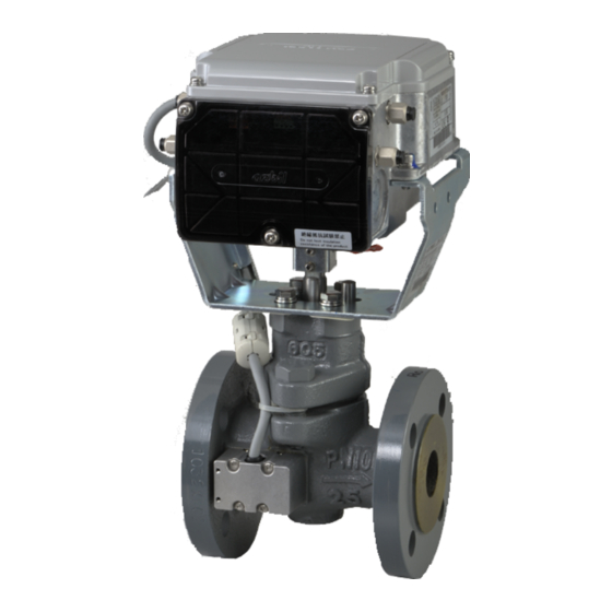
Flow Measurement and Control Valve Model
FVY5137J/FVY5147J/FVY5157J is a series of motorized
two-way valves with flanged-end connection. DN15 to DN80
rotary valve and actuator are integrated in a single unit.
In combination with the functions of a control valve, Model
FVY5137J/FVY5147J/FVY5157J measures and controls flow.
Model FVY5137J/FVY5147J/FVY5157J thus enables to control
temperature for air conditioning by controlling chilled/hot water
volume and to measure chilled/hot water flow.
For such a high functionality, compact size and simple
installation of Model FVY5137J/FVY5147J/FVY5157J are
incomparable.
3 kinds of control signals are available to operate Model
FVY5137J/FVY5147J/FVY5157J.
- 4-20 mA DC input:
Provides proportional control in combination with a DDC
controller. (e.g., Infilex
R35/R36)
- 2-10 V DC input:
Provides proportional control in combination with a DDC controller. (e.g., Infilex
- 0-10 V DC input:
Provides proportional control in combination with a DDC controller.
Flow data stored in Model FVY5137J/FVY5147J/FVY5157J is retrieved via RS-485 communication (Modbus protocol). The
retrieved flow data is effective for energy-saving facility operation.
Note: ∗ DDC: Direct Digital Control
Features
•
Compact and lightweight:
Rotary valve actualizes small body and light weight.
•
Valve and actuator integrated in a single unit.
•
Model FVY5137J/FVY5147J/FVY5157J holds flow data
effective for maintenance and energy-saving facility
operation.
The
data
communication (Modbus protocol).
•
Valve for chilled/hot water control applicable to large Cv
value, high rangeability, and low leakage.
•
Durable actuator with low power consumption.
IMPORTANT:
Do not use the data measured by Model FVY5137J/FVY5147J/FVY5157J for charging or dealing purposes.
™
Flow Measurement and Control Valve
Standalone Model
(PN10 / GG-20)
™
GC Model WY5111, Model
is
retrieved
via
RS-485
™
AC Model WY5117)
•
Flow control/position control operation selectable:
For flow control, flow characteristic is selectable (equal
percentage or linear). For position control, flow
characteristic is equal percentage.
•
In
combination
QY5010S1000) and the insertion-type pipe temperature
sensor (Model TY7830) or the temperature sensor for
pipe surface (Model TY7820), pressure, temperature,
and flow can be displayed on the Display Panel.
•
CE Marking certified product:
Models FVY5137J, FVY5147J, and FVY5157J conform
to all the applicable standards of CE Marking.
1
AB-7046
Specifications/Instructions
with
Display
Panel
(Model
Advertisement
Table of Contents

Related Manuals for Azbil Actival FVY5147J


Summary of Contents for Azbil Actival FVY5147J
- Page 1 AB-7046 Specifications/Instructions ™ ACTIVAL Flow Measurement and Control Valve Standalone Model (PN10 / GG-20) General ™ ACTIVAL Flow Measurement and Control Valve Model FVY5137J/FVY5147J/FVY5157J is a series of motorized two-way valves with flanged-end connection. DN15 to DN80 rotary valve and actuator are integrated in a single unit. In combination with the functions of a control valve, Model FVY5137J/FVY5147J/FVY5157J measures and controls flow.
-
Page 2: Safety Instructions
This product is targeted for general air conditioning. Do not use this product in a situation where human life may be affected. If this product is used in a clean room or a place where reliability or control accuracy is particularly required, please contact Azbil Corporations’... - Page 3 AB-7046 CAUTION (2/2) • When installing the product with flange gasket, do not allow the flange gasket to go inside the pipe. Doing so might cause incorrect measurement and control of flow. • Do not use rubber gaskets. Doing so might cause incorrect measurement and control of flow.
-
Page 4: Model Numbers
AB-7046 Model Numbers Model FVY5137J/FVY5147J/FVY5157J is the model for the valve and actuator integrated into a single unit. The model number label is attached to the yoke. Base Actuator Valve Valve Actuator ⎯ model control rating/ size/Cv Description type number signal material value... -
Page 5: Valve Specifications
AB-7046 Specifications For weight, refer to the table shown in the section Dimensions. Valve and actuator (as a single unit) specifications Item Specification Rated operating condition Transport/storage conditions (packaged) Environmental conditions -20 °C to 50 °C -20 °C to 70 °C Ambient temperature (Do not allow process fluid to freeze.) Ambient humidity... -
Page 6: Actuator Specifications
AB-7046 Actuator specifications Item Specification 24 V AC ± 15 %, 50 Hz/60 Hz Power supply Power consumption 8 VA 63 ± 5 sec (50 Hz) / 53 ± 5 sec (60 Hz) Timing 4-20 mA DC input (Input impedance: 250 Ω) Control signal Model FVY5137J Model FVY5147J... -
Page 7: Measuring Range And Accuracy
AB-7046 Measuring range and accuracy IMPORTANT: Flow measuring accuracy shown in the below is for the valve sensor measuring 7 to 17 °C and 45 to 65 °C ranges, 0.1 to 0.8 MPa pipe pressure, and 0.03 to 0.3 MPa differential pressure. Without these ranges, the flow rate measuring accuracy may lower. - Page 8 AB-7046 (2/2) Item Specification Pressure Measuring range 0 MPa to 1.0 MPa* measuring ± 0.5 %FS (factory preset) * Accuracy -10 °C to 100 °C Temperature Measuring range measuring ± 1.0 °C (factory preset) in the 0 °C to 80 °C measuring range* Accuracy (within 0 °C to 80 °C measuring range, at -25 °C to 40 °C temperature difference between measuring temperature and ambient temperature)
-
Page 9: Wire Specifications
AB-7046 Data in Model FVY5137J/FVY5147J/FVY5157J Data type Description Flow data Following items are displayed on Display Panel (Model QY5010S1000): Actual flow, supply water temperature, return water temperature, valve inlet pressure, valve outlet pressure, actual flow (% in bar graph), actual valve position (% in bar graph) Following items are output in analog signal using RS-485/analog output signal converter (Model RYY792C3001): Control setting value, actual valve position, actual flow, set flow, supply water temperature, return water... - Page 10 AB-7046 CE Marking Conformity This product complies with the following Electromagnetic Compatibility (EMC). EMC : EN61000-6-2, EN55011 Class A Dimensions Model with DN15 valve N × φh...
- Page 11 AB-7046 Model with DN25 to DN80 valve Flow direction indication N × φh Valve sensor cable Valve sensor (in valve sensor cover) Valve size Weight φC (mm) φD (mm) φg (mm) φh (mm) Model number H (mm) (mm) L (mm) (mm) t (mm) (DN)
- Page 12 AB-7046 DN25 to DN80 valve Top cover Top cover Terminal cover Actuator Knockout hole Terminal cover Yoke Gland Pointer Bonnet Joint Seat ring O-ring Gland packing Stem Valve body Spring Heat insulation Plug Figure 2. Parts identification: Valve details Actuator details (Connectors, ports, terminals, and LED) Reset switch Connector for Pt100 input Row T1: Supply water temperature...
-
Page 13: Installation Location
AB-7046 Installation Precautions for installation Installation location CAUTION CAUTION • Installation and wiring must be performed by • Do not use the product in an atmosphere qualified personnel in accordance with all containing oxidizing gas, explosive gas, etc. ... -
Page 14: Mounting Position
AB-7046 Mounting position Model FVY5137J/FVY5147J/FVY5157J can be mounted in any position ranging from upright to sideways (90° tilted). Note that Model FVY5137J/FVY5147J/FVY5157J must be installed with the valve sensor vertically positioned above the valve body when being tilted. It is also installable on the vertical upflow pipe. (See Fig. 5.) However, Model FVY5137J/FVY5147J/FVY5157J must be installed always in upright position outdoors. - Page 15 AB-7046 Factory preset position The actuator shaft is positioned at 100 % (in fully open position) for shipment. The shaft is thus completely turned clockwise, and the pointer points at ‘100’. (See Fig. 6.) Pointer Figure 6. Pointer position for shipment Manually opening/closing valve IMPORTANT: •...
-
Page 16: Wiring Procedure
AB-7046 Wiring CAUTION • Installation and wiring must be performed by qualified personnel in accordance with all applicable safety standards. • Before wiring and maintenance, be sure to turn off the power to the product. Failure to do so might cause electric shock. IMPORTANT: •... - Page 17 AB-7046 5) Connect the wires of each line. After connecting the wires, lightly pull them from the wiring ports so that minimum wire slack remains inside the actuator. Too long wire slack inside the actuator may block the terminal cover to close or may hold down the reset switch and interrupt the operation.
- Page 18 AB-7046 Wires connection of Display Panel Terminal Wire color* Description 12 V DC R B W R: RED Black B: BLK White AP-bus (+) W: WHT Green AP-bus (-) G: GRN Note: ∗ Wire color of the Display Panel shown in the above table is the wire colors of the Figure 16.
-
Page 19: Precautions For Connection
AB-7046 Precautions for connection RS-485 communication (See Figs. 26 and 27.): • Pass the cable of RS-485 communication through a wiring port (knockout hole) on the other side of the wiring port for power supply cable. Attach the optional cable gland with three ports (Model DY7000A1000) to the wiring port to share the wiring port with signal lines. -
Page 20: Connection Examples
AB-7046 Connection examples Controller Isolator* (e.g. Model R35/R36TC0) Isolator* Controller Model FVY5137J Model FVY5137J (e.g. Model R35/R36TC0) (4-20 mA input) (4-20 mA input) Isolator* Isolator* Controller Power Power Model FVY5137J Model FVY5137J Power (e.g. Model R35/R36TC0) (4-20 mA input) (4-20 mA input) Notes: Notes: ∗1 Provide an isolator for the controller not internally isolated. - Page 21 AB-7046 Slave (Model R series) Master Isolator* Controller Model FVY5157J (e.g. Third party (0-10 V input) controller) Slave (Model FVY51X7J: this product) Figure 26. Connection example: 3-wire RS-485 communication Isolator* Power Model FVY5157J Notes: (0-10 V input) ∗1 Provide an isolator for the controller not internally isolated. ∗2 Terminals 2, 6, and 8 of the product are internally connected.
- Page 22 AB-7046 Cable Gland with Three Ports Attaching the cover to the base Cable gland with three ports (Model DY7000A1000) is Attach the cover to the base and fix them by locking the 3 recommended to attach to a wiring port (knock out hole) of latches.
- Page 23 AB-7046 2) Connect the seal connectors (optional) to the cover of 6) Lead the wires (sheath stripped part of cables) through the cable gland. the wiring port (where the base of the cable gland is attached) of the product. Then, attach the cover of the IMPORTANT: cable gland to the base.
-
Page 24: Inspection And Troubleshooting
If your problem is not solved by the corresponding action, please contact Azbil Corporation near you. • Be sure to completely close the terminal cover and the top cover. - Page 25 AB-7046 Table 1. Inspection items and details Inspection item Inspection interval Inspection detail • Visual inspection Semiannual Fluid leakage from the gland and the flange face • Loosened bolts • Valve and actuator damages • Operating status Semiannual Unstable open/close operation •...
- Page 26 AB-7046 This blank page is added for page layout purposes.
- Page 27 AB-7046 This blank page is added for page layout purposes.
- Page 28 AB-7046 ACTIVAL and Infilex are trademarks of Azbil Corporation in Japan or in other countries. KPEV is a registered trademark of Furukawa Electric Co., Ltd. Specifications are subject to change without notice. Building Systems Company 1-12-2 Kawana, Fujisawa, Kanagawa 251-8522 JAPAN http://www.azbil.com/...
Need help?
Do you have a question about the Actival FVY5147J and is the answer not in the manual?
Questions and answers