Arcteq AQ-103 Instruction Manual
Arc flash protection device
Hide thumbs
Also See for AQ-103:
- Instruction manual (44 pages) ,
- Instruction manual (47 pages) ,
- Instruction manual (19 pages)
Table of Contents
Advertisement
Quick Links
Advertisement
Table of Contents

Subscribe to Our Youtube Channel
Related Manuals for Arcteq AQ-103


Summary of Contents for Arcteq AQ-103
- Page 1 AQ-103 Arc flash protection device Instruction manual...
-
Page 2: Table Of Contents
12 Testing esting ......................................................45 12.1 Testing the light-only mode ....................45 12.2 Testing the light and current mode ..................45 12.3 Testing the operation time ....................46 12.4 Test plan example ......................47 © Arcteq Relays Ltd IM00046... - Page 3 14.15 Casing..........................54 15 Or 15 Ordering inf dering informa ormation tion ..............................................55 16 Contact and r 16 Contact and re e f f er erence inf ence informa ormation tion......................................57 © Arcteq Relays Ltd IM00046...
- Page 4 Nothing contained in this document shall increase the liability or extend the warranty obligations of the manufacturer Arcteq Relays Ltd. The manufacturer expressly disclaims any and all liability for any damages and/or losses caused due to a failure to comply with the instructions contained herein or caused by persons who do not fulfil the aforementioned requirements.
-
Page 5: Document Inf
1.02 Date January 2023 - Updated the Arcteq logo on the cover. - Updated the distance between the flash and the unit in the "Testing the unit operation time" chapter. - Unified terminology used througout the manual (e.g. unit and device means the same thing. - Page 6 A A Q Q -103 -103 1 Document information Instruction manual Version: 1.06 Changes - Updated Modbus map in Modbus communication chapter. R R e e vision vision 1.06 1.06 Date September 2024 Changes - Added point sensor dimensions. © Arcteq Relays Ltd IM00046...
-
Page 7: Saf Y Informa Ormation Tion
Please note that although these warnings relate to direct damage to personnel and/or equipment, it should be understood that operating damaged equipment may also lead to further, indirect damage to personnel and/or equipment. Therefore, we expect any user to fully comply with these special messages. © Arcteq Relays Ltd IM00046... -
Page 8: Abbr Bbre E Via Viations Tions
NC – normally closed NO – normally open PCB – printed circuit board RF – radio frequency Rx – receiver SAS – standard arc scheme SF – system failure Tx – transceiver μP - microprocessor © Arcteq Relays Ltd IM00046... -
Page 9: General
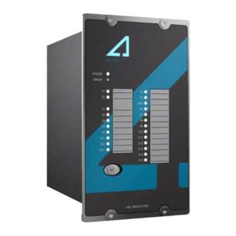
Figure. 4 - 1. Arc protection device AQ-103. The AQ-103 is designed according to the latest protection relay standards and it is therefore suitable for installations in rough environments. These include utilities and power plants (both traditional and renewable), various heavy industry applications (oil, gas, mining, steel, etc.) as well as commercial and... - Page 10 5 Device features AQ-103 is an arc flash protection device which can be applied to a variety of applications. It can be used on its own as a stand-alone device, or it can be a part of a more complex arc protection system by using binary inputs and outputs to connect multiple AQ 100 series devices together.
-
Page 11: Connections
Version: 1.06 6 Connections The figure below depicts the connections of AQ-103(LV). Please note that the SF relay is in the de- energized position; also note that the device has been halved for the image to allow for space for all connector explanations. - Page 12 A A Q Q -103 -103 6 Connections Instruction manual Version: 1.06 Figure. 6.1 - 3. Simplified block diagram of the AQ-103 with optional Modbus add-on. © Arcteq Relays Ltd IM00046...
-
Page 13: Inputs
For more information on sensors, please refer to the Arc sensors chapter as well as to the AQ-0x instruction booklet which can be found on Arcteq's website (https://www.arcteq.fi/downloads/). For more information on AQ-1000 arc quenching device (AQD) please refer to the AQ-1000 Instruction manual. -
Page 14: Binary Inputs
AQ 100 series device's binary outputs send out a short pulse every second. Binary inputs of the receiving AQ 100 series devices use these pulses to count the number of connected binary outputs. System self-supervision chapter for more information. NOTICE! TICE! Please note that the binary ouputs are polarity-sensitive. © Arcteq Relays Ltd IM00046... -
Page 15: High-Speed Output(S)
SF relay changes its state. The state stays this way until the device returns to a healthy condition. See the System self-supervision chapter for more information. 6.4 Auxiliary voltage Figure. 6.4 - 10. Auxiliary power supply connection © Arcteq Relays Ltd IM00046... - Page 16 -103 6 Connections Instruction manual Version: 1.06 The auxiliary power supply voltage is 92….265 V AC/DC. Alternatively, the optional auxiliary power supply can be of 18…72 V DC. This choice must be specified when ordering. © Arcteq Relays Ltd IM00046...
-
Page 17: Arc Sensors C Sensors
Up to three (3) sensors can be connected in series (with the exception of AQ-103 which can take only one point sensor per channel). Installing a connection cable is simple as each end of the sensor has a detachable cover over the cable connectors. -
Page 18: Arc Light And Pressure Point Sensor Aq-02
AQ-02 can also be ordered with 25,000 lux or 50,000 lux thresholds. Its detection radius is 180 degrees. The pressure threshold is fixed at 0.2 bar above ambient pressure. Figure. 7.2 - 13. AQ-02 arc light and pressure point sensor. © Arcteq Relays Ltd IM00046... -
Page 19: Arc Light Fiber Optic Loop Sensor Aq-06
Up to three (3) sensors can be connected in series (with the exception of AQ-103 which can take only one point sensor per channel). Installing a connection cable is simple as each end of the sensor has a detachable cover over the cable connectors. -
Page 20: Arc Light Fiber Optic Loop Sensor Aq-07
If necessary, the ends of an AQ-07 cable can be ordered with heat shrinking tubing to avoid light detection outside the protected zone. The covered area can be one (1) or two (2) meters by default; if other lengths are required, please consult the Arcteq sales team. You can find the Contact and reference information page at the end of this manual. - Page 21 4. Run the auto-configuration procedure. See System setup for more details. NOTICE! TICE! If the cable has a shield (copper or tinned copper), it is recommended to connect it to same ground as the device. © Arcteq Relays Ltd IM00046...
-
Page 22: Operation And Config Tion And Configura Uration Tion
The trip relays (T1–T4) Enables or disables and high-speed output The trip relays and high-speed output latching latching of trip relays and operate as latching is disabled. high-speed output. outputs. © Arcteq Relays Ltd IM00046... -
Page 23: Available Logic Schemes
Switch 4: 0 8.2 Available logic schemes The schemes described below are the most commonly used ones for AQ-103 devices. The schemes are configured using the first DIP switch group (SW1) and its switches 1…3 ("Scheme selection"). The scheme selection is based on binary arithmetic: •... -
Page 24: Ss:0 (Main)
BI2. External light signal closes all trip contacts (T1–T4). All light signals activate HSO alarm signal. Arc quenching device (AQD) control can be activated with any light signal. Figure. 8.2.1 - 19. Example application with AQ-103 (SS:0). © Arcteq Relays Ltd IM00046... -
Page 25: Ss:1 (Main)
100 series device) can be connected to BI2. External light signal closes all trip contacts (T1–T4). All light signals activate HSO alarm signal. Arc quenching device (AQD) control can be activated with S3 to S15 and with BI2. © Arcteq Relays Ltd IM00046... -
Page 26: Ss:2 (Main-Tie-Main)
Figure. 8.2.2 - 23. Simplified logic diagram of SS:1. 8.2.3 SS:2 (main–tie–main) The logic scheme SS:2 is designed for incoming feeder selective arc protection. It can be used for substations with one or more incoming feeders. © Arcteq Relays Ltd IM00046... - Page 27 Instruction manual Version: 1.06 Figure. 8.2.3 - 24. Example application with AQ-103 (SS:2). If a fault is detected in the incoming feeder cable compartment (S1), circuit breakers on both sides of the transformer will be tripped with T1 and T2.
-
Page 28: Ss:3
2. Activates only if overcurrent signal (BI1) is ON. Figure. 8.2.3 - 26. Simplified logic diagram of SS:2. 8.2.4 SS:3 The logic scheme SS:3 is mainly used in selective outgoing feeder arc protection solutions. This scheme is able to protect four outgoing feeders. © Arcteq Relays Ltd IM00046... - Page 29 1. Activates only if channels have been set to light only mode or overcurrent signal (BI1) is ON. NOTICE! TICE! The AQD output is not available with this scheme! If AQ-103 must be used for the AQD output, another scheme should be selected. © Arcteq Relays Ltd...
-
Page 30: Ss:4
The logic scheme SS:4 is mainly used in selective outgoing feeder arc protection solutions. This scheme is able to protect four outgoing feeders. This scheme is a modification of SS:3. BI2 is used for receiving master trip signal. Figure. 8.2.5 - 30. Example application with AQ-103 (SS:4). © Arcteq Relays Ltd IM00046... - Page 31 1. Activates only if channels have been set to light only mode or overcurrent signal (BI1) is ON. NOTICE! TICE! The AQD output is not available with this scheme! If AQ-103 must be used for the AQD output, another scheme should be selected for the incoming feeder relay. Figure. 8.2.5 - 32. Simplified logic diagram of SS:4.
-
Page 32: Push Button (Set)
DIP switches must be moved back and forth once before the system setup procedure is carried out. You can reconfigure a device with more connections at any time without having to move one of the DIP switches. © Arcteq Relays Ltd IM00046... -
Page 33: Reset
Scheme selection chapter for more information). 8.5 LED indicator functions The AQ-103 device has twenty-five (25) indication LEDs on the device's front panel.. Apart from the “Power” and “Error” LEDs, the user can write their own identifications for each of the remaining LEDs on the text insert sheet located in the transparent pockets next to the LEDs. -
Page 34: Modbus Communication
It is mainly designed for connecting to AQ-250 series device but any Modbus master can be used. If AQ-103 has a modbus connection to an AQ-250 series device, the AQ-250 series device can record events, display faults on the display and report the events forward to SCADA system. - Page 35 Version: 1.06 Using AQ-250 series device as a master The signals received from AQ-103 device can be used for fault indications on AQ-250 device and for reporting the signals forward with IEC 61850 or other communication protocol. Fault indication can be done by setting up an alarm display for each incoming signal or by building a mimic.
- Page 36 Figure. 8.7 - 35. Example mimic where sensor activation location is indicated with a symbol. Figure. 8.7 - 36. In AQ-S254 it is possible to set up the display to show sensor activations in alarm display. © Arcteq Relays Ltd IM00046...
- Page 37 SW1:8 SW1:7 SW1:6 SW1:5 SW1:4 SW1:3 SW1:2 SW1:1 Serial number 5-6 (40005) SN24 SN23 SN22 SN21 SN20 SN19 SN18 SN17 Latched sensor 7 (40007) activations Latched I/O activations 8 (40008) Sensor error 9 (40009) Clear latched signals 11 (40011) © Arcteq Relays Ltd IM00046...
-
Page 38: Non-Volatile Memory
This feature is especially important if tripping causes the device to lose its auxiliary power. The non-volatile memory does not require a power supply to maintain the information and it retains the settings and the indications permanently without power. © Arcteq Relays Ltd IM00046... -
Page 39: Sy Y St Stem Self-Super 9 S Em Self-Supervision Vision
The device goes into Error mode, if a DIP switch setting is changed after the system setup procedure has been performed. However, the configured (stored) settings are still valid and the device is still operational. © Arcteq Relays Ltd IM00046... - Page 40 A A Q Q -103 -103 10 Wiring example Instruction manual Version: 1.06 10 Wiring example Figure. 10 - 37. Example wiring diagram for AQ-103. © Arcteq Relays Ltd IM00046...
-
Page 41: Dimensions And Installa Imensions And Installation Tion
The figure below presents the dimension of the device visually. It also shows the dimensions of the cut- out (bottom-left) required when mounting the device on a panel. Figure. 11 - 38. Dimensions of the device. © Arcteq Relays Ltd IM00046... - Page 42 A A Q Q -103 -103 11 Dimensions and installation Instruction manual Version: 1.06 Figure. 11 - 39. Installing a AQ-100 series device to a door. © Arcteq Relays Ltd IM00046...
- Page 43 A A Q Q -103 -103 11 Dimensions and installation Instruction manual Version: 1.06 Point sensors Figure. 11 - 40. Dimensions of arc flash sensors. Figure. 11 - 41. Installing an arc flash sensor. © Arcteq Relays Ltd IM00046...
- Page 44 2. Install protective covers in the holes to ensure the sensor cable remains unharmed by rough edges. 3. Run the sensor cable through the holes and along the protected area. Fasten it to the compartment walls with cable clips or some other appropriate anchoring method. © Arcteq Relays Ltd IM00046...
- Page 45 Instruction manual Version: 1.06 4. Turn the black and blue receiver (“Rx”) and transceiver (“Tx”) screws counter-clockwise and plug in the sensor cable terminals. Then turn the screws clockwise to secure the terminals in their place. © Arcteq Relays Ltd IM00046...
-
Page 46: Testing Esting
9. Activate the camera flash within 30 cm (12 inches) of the sensor but do not activate the binary input used for the overcurrent condition (I>). 10. Verify that no trip has occured and only the indicator LED of the sensor activation is lit. © Arcteq Relays Ltd IM00046... -
Page 47: Testing The Operation Time
If you want to have more information of these tests, please refer to the routine test reports sent with the AQ-103(LV) device and/or consult your nearest Arcteq representative for the type test reports. -
Page 48: Test Plan Example
A A Q Q -103 -103 12 Testing Instruction manual Version: 1.06 12.4 Test plan example © Arcteq Relays Ltd IM00046... -
Page 49: Tr R Oubleshoo 13 T Oubleshooting Ting
A A Q Q -103 -103 13 Troubleshooting Instruction manual Version: 1.06 13 Troubleshooting Table. 13 - 8. Troubleshooting guide for AQ-103 variants. P P r r oblem oblem P P ossible sol ossible solution( ution(s) s) Check the sensor's cable wiring. -
Page 50: Mounting And Installation
14.3 Auxiliary voltage Table. 14.3 - 11. Technical data for the relay auxiliary voltage (Uaux). 92…265 V AC/DC Auxiliary power supply 18…72 V DC (optional) Maximum power consumption 5 W, < 10 mΩ Standby current 90 mA © Arcteq Relays Ltd IM00046... -
Page 51: Binary Inputs
250 V DC Carry: - continuous carry - make-and-carry for 3 s - make-and-carry for 0.5 s 15 A Breaking capacity DC* 1 A/110 W Contact material semiconductor *) When the time constant L/R = 40 ms. © Arcteq Relays Ltd IM00046... -
Page 52: Binary Output(S)
Light intensity threshold 25,000 lux 50,000 lux Detection radius 180º Mechanical protection IP 20 Sensor cable specification Shielded twisted pair 0.75 mm (AWG: 18) Maximum sensor cable length (per 200 m channel) Operating temperature –20…+85 ºC © Arcteq Relays Ltd IM00046... -
Page 53: Fiber Optic Loop Sensors
AQ-07 fiber optic loop sensor Table. 14.10 - 20. Technical data for the AQ-07 fiber optic loop sensor. Material Covered glass fiber Light intensity threshold 8,000 lux Cable length (min…max) 3…50 m Cable diameter 1.2 mm Detection radius 360º © Arcteq Relays Ltd IM00046... -
Page 54: Disturbance Tests
= 150 kHz…80 MHz, 10 V/m (EN 61000-4-6, level 3) 14.12 Voltage tests Table. 14.12 - 23. Technical data for the voltage tests. Insulation test voltage (IEC 60255-5) 2 kV, 50 Hz, 1 min © Arcteq Relays Ltd IM00046... -
Page 55: Mechanical Tests
Table. 14.15 - 26. Technical data for the device casing. Protection: - front IP 52 - back IP 20 Device dimensions (W × H × D) 102 × 177 × 161 mm Weight 1.2 kg © Arcteq Relays Ltd IM00046... -
Page 56: Ordering Inf Dering Informa Ormation Tion
A A Q Q -103 -103 15 Ordering information Instruction manual Version: 1.06 15 Ordering information AQ-103 arc flash protection device AQ-0x point sensors © Arcteq Relays Ltd IM00046... - Page 57 AQ-0x fiber optic loop sensors Accessories Order Description Note Manufacturer code Wall mounting AQX006 For AQ-103 and AQ-110x variants (MV and LV). Arcteq Ltd. bracket Wall mounting For AQ-101, AQ-101S and AQ-102 devices (MV and AQX016 Arcteq Ltd. bracket LV).
-
Page 58: Contact And R Ence Informa Ormation Tion
Arcteq Relays Ltd. Visiting and postal address Kvartsikatu 2 A 1 65300 Vaasa, Finland Contacts Phone: +358 10 3221 370 Website: arcteq.com Technical support: arcteq.com/support-login +358 10 3221 388 (EET 9:00 – 17.00) E-mail (sales): sales@arcteq.fi © Arcteq Relays Ltd IM00046...
Need help?
Do you have a question about the AQ-103 and is the answer not in the manual?
Questions and answers