Table of Contents
Advertisement
Quick Links
Advertisement
Table of Contents

Related Manuals for Arcteq AQ-V211


Summary of Contents for Arcteq AQ-V211
- Page 1 AQ-V211 Voltage protection IED Instruction manual...
-
Page 2: Table Of Contents
4.10 Configuring user levels and their passwords............... 50 5 Functions unctions ...................................................... 53 5.1 Functions included in AQ-V211.................... 53 5.2 Measurements........................54 5.2.1 Voltage measurement and scaling ................54 5.2.2 Frequency tracking and scaling ................. 65 5.3 Protection functions ......................68 5.3.1 General properties of a protection function .............. - Page 3 7 Connections and applic 7 Connections and applica a tion examples tion examples..................................248 7.1 Connections of AQ-V211....................248 7.2 Application example and its connections................250 7.3 Trip circuit supervision (95) ....................251 8 Construction and installa 8 Construction and installation tion ....................
- Page 4 A A Q Q -V211 -V211 Instruction manual Version: 2.04 9.2.2.2 Object control and monitoring..............288 9.2.2.3 Vector jump (Δφ; 78) .................. 288 9.2.2.4 Synchrocheck (ΔV/Δa/Δf; 25) ..............289 9.2.3 Monitoring functions ....................290 9.2.3.1 Voltage transformer supervision (60) ............290 9.2.3.2 Disturbance recorder..................
- Page 5 Nothing contained in this document shall increase the liability or extend the warranty obligations of the manufacturer Arcteq Relays Ltd. The manufacturer expressly disclaims any and all liability for any damages and/or losses caused due to a failure to comply with the instructions contained herein or caused by persons who do not fulfil the aforementioned requirements.
- Page 6 A A Q Q -V211 -V211 Instruction manual Version: 2.04 Copyright Copyright © Arcteq Relays Ltd. 2021. All rights reserved.
-
Page 7: Document Inf
A A Q Q -V211 -V211 Instruction manual Version: 2.04 1 Document information 1.1 Version 2 revision notes Table. 1.1 - 1. Version 2 revision notes Revision 2.00 Date 6.6.2019 - New more consistent look. - Improved descriptions generally in many chapters. - Improved readability of a lot of drawings and images. -
Page 8: Version 1 Revision Notes
- Improvements to many drawings and formula images. - Improved and updated IED user interface display images. - AQ-V211 Functions included list Added: Voltage memory, indicator objects, switch-on-to-fault, vector jump protection, programmable control switch, mA output control and measurement recorder. - Page 9 A A Q Q -V211 -V211 Instruction manual Version: 2.04 Date 22.11.2013 Changes - Application example for trip circuit supervision. Revision 1.02 Date 30.1.2014 Changes - Added df/dt and synchrocheck. Revision 1.03 Date 27.1.2015 Added RTD&mA input module, Double LC 100Mb Ethernet card module and Serial RS232 & serial fiber module hardware descriptions.
-
Page 10: Abbr Bbre E Via Viations Tions
A A Q Q -V211 -V211 Instruction manual Version: 2.04 2 Abbreviations AI – Analog input AR – Auto-recloser ASDU – Application service data unit AVR – Automatic voltage regulator BCD – Binary-coded decimal CB – Circuit breaker CBFP – Circuit breaker failure protection CLPU –... - Page 11 A A Q Q -V211 -V211 Instruction manual Version: 2.04 IGBT – Insulated-gate bipolar transistor I/O – Input and output IRIG-B – Inter-range instruction group, timecode B LCD – Liquid-crystal display LED – Light emitting diode LV – Low voltage NC –...
-
Page 12: General
Version: 2.04 3 General The AQ-V211 voltage protection IED is a member of the AQ-200 product line. The hardware and software are modular: the hardware modules are assembled and configured according to the application's I/O requirements and the software determines the available functions. This manual describes the specific application of the AQ-V211 voltage protection IED. -
Page 13: Ied User Interface Erface
A A Q Q -V211 -V211 Instruction manual Version: 2.04 4 IED user interface 4.1 Panel structure The user interface section of an AQ-200 series device is divided into two user interface sections: one for the hardware and the other for the software. You can access the software interface either through the front panel or through the AQtivate freeware software suite. -
Page 14: Mimic And Main Menu
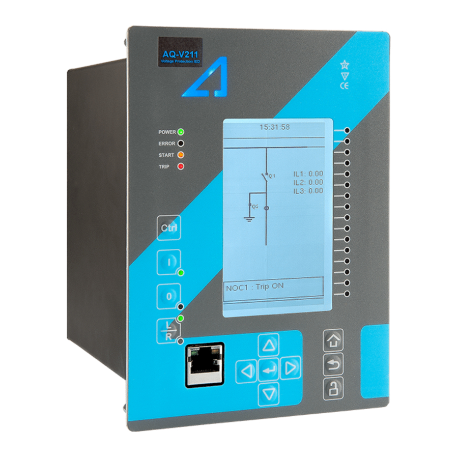
A A Q Q -V211 -V211 Instruction manual Version: 2.04 The sixteen freely configurable LEDs are located on the right side of the display. Their activation and color (green or yellow) are based on the settings the user has put in place in the software. Holding the I I (object control) button down for five seconds brings up the button test menu. -
Page 15: General Menu
A A Q Q -V211 -V211 Instruction manual Version: 2.04 • Control • Communication • Measurement • Monitoring. They are presented in the image below. The available menus vary according to the device type. Figure. 4.2.2 - 3. Main configuration menus. 4.3 General menu The General main menu is divided into two submenus: the Device info tab presents the information of the device, while the Function comments tab allows you to view all comments you have added to the... - Page 16 A A Q Q -V211 -V211 Instruction manual Version: 2.04 Device info Figure. 4.3 - 5. Device info. Table. 4.3 - 3. Parameters and indications in the General menu. Name Range Step Default Description Device name Unitname The file name uses these fields when loading the .aqs configuration file from the AQ-200 unit.
- Page 17 A A Q Q -V211 -V211 Instruction manual Version: 2.04 Name Range Step Default Description 0: User defined 1: English 2: Finnish Changes the language of the parameter descriptions in 3: Swedish the HMI. If the language has been set to "Other" in the Language 4: Spanish 1: English...
-
Page 18: Protection Menu
A A Q Q -V211 -V211 Instruction manual Version: 2.04 Figure. 4.3 - 6. Function comments. 4.4 Protection menu General Figure. 4.4 - 7. Protection menu structure The Protection main menu includes the Stage activation submenu as well as the submenus for all the various protection functions, categorized under the following modules: "Arc protection", "Current", "Voltage", "Frequency", "Sequence"... - Page 19 A A Q Q -V211 -V211 Instruction manual Version: 2.04 Figure. 4.4 - 8. Protection menu view. Stage activation You can activate the various protection stages in the Stage activation submenu (see the images below). Each protection stage and supporting function is disabled by default. When you activate one of the stages, its activated menu appears in the stage-specific submenu.
- Page 20 A A Q Q -V211 -V211 Instruction manual Version: 2.04 Example of a protection stage and its use Once a protection stage has been activated in the Stage activation submenu, you can open its own submenu. In the image series below, the user has activated three current stages. The user accesses the list of activated current stages through the "Current"...
- Page 21 A A Q Q -V211 -V211 Instruction manual Version: 2.04 • Function condition: indicates the stage's condition which can be Normal, Start, Trip, or Blocked. • Expected operating time: Expected time delay from detecting a fault to tripping the breaker. This value can vary during a fault if an inverse curve time delay (IDMT) is used.
- Page 22 A A Q Q -V211 -V211 Instruction manual Version: 2.04 Figure. 4.4 - 13. Registers. Register menu content is not available in the HMI. It can only be accessed with AQtivate setting tool. Stored in the "Registers" section you can find both "Operation event register" and "General event register".
- Page 23 A A Q Q -V211 -V211 Instruction manual Version: 2.04 Figure. 4.4 - 14. I/O. The "I/O" section is divided into two subsections: "Direct output control" and "Blocking input control". In "Direct output control" you can connect the stage's signals to physical outputs, either to an output relay or an LED (START or TRIP LEDs or one of the 16 user configurable LEDs).
-
Page 24: Control Menu
A A Q Q -V211 -V211 Instruction manual Version: 2.04 Figure. 4.4 - 15. Events. You can mask on and mask off the protection stage related events in "Event mask". By default events are masked off. You can activate the desired events by masking them ("x"). Remember to save your maskings by confirming the changes with the check mark icon. - Page 25 A A Q Q -V211 -V211 Instruction manual Version: 2.04 Controls enabled Figure. 4.5 - 16. Controls enabled submenu. You can activate the selected control functions in the Controls enabled submenu. By default all the control functions are disabled. All activated functions can be viewed in the Control functions submenu (see the section "Control functions"...
- Page 26 A A Q Q -V211 -V211 Instruction manual Version: 2.04 • SG loc SG local select al select: selects the local control for the different setting groups (can use digital inputs, logical inputs or outputs, RTDs, object status information as well as stage starts, trips or blocks).
- Page 27 A A Q Q -V211 -V211 Instruction manual Version: 2.04 Figure. 4.5 - 20. Settings section. OBJECT SET AND STATUS • L L oc ocal/R al/Remo emot t e sta e stat t us us: control access may be set to Local or Remote (Local by default; please note that when local control is enabled, the object cannot be controlled through the bus and vice versa).
- Page 28 A A Q Q -V211 -V211 Instruction manual Version: 2.04 • An object has both Open input Open input and C C lose input lose input signals which are used for indicating the status of the breaker on the HMI and in SCADA. Status can be indicated by any of the following: digital inputs, logical inputs or outputs.
- Page 29 A A Q Q -V211 -V211 Instruction manual Version: 2.04 Figure. 4.5 - 21. Application control section. You can connect object statuses directly to specific physical outputs in the "Signal connections" subsection ( Control → Application control ). A status can be connected to output relays, as well as to user-configurable LEDs.
- Page 30 A A Q Q -V211 -V211 Instruction manual Version: 2.04 The "Registers"section stores the function's specific fault data. There are twelve (12) registers, and each of them includes data such as opening and closing times, command types and request failures. The data included in the register depend on the protection function.
- Page 31 A A Q Q -V211 -V211 Instruction manual Version: 2.04 Each control function that has been activated is listed in the Control functions submenu (see the middle image above). This submenu includes the following sections: "Info", "Settings", "Registers", "I/O" and "Events".
- Page 32 A A Q Q -V211 -V211 Instruction manual Version: 2.04 The stage settings vary depending on which control function they are a part of. By default only one setting group of the eight available setting groups is activated. You can enable more groups in the Control →...
- Page 33 A A Q Q -V211 -V211 Instruction manual Version: 2.04 Figure. 4.5 - 28. I/O section. The "I/O" section is divided into two subsections: "Direct output control" and "Blocking input control". In "Direct output control" you can connect the stage's signals to physical outputs, either to an output relay or an LED (START or TRIP LEDs or one of the 16 user configurable LEDs).
- Page 34 A A Q Q -V211 -V211 Instruction manual Version: 2.04 Figure. 4.5 - 29. Events section. You can mask on and mask off events related to an object's stage in "Event mask". By default all events are masked off. You can activate the desired events by masking them ("x"). Please remember to save your maskings by confirming the changes with the check mark icon.
- Page 35 A A Q Q -V211 -V211 Instruction manual Version: 2.04 Figure. 4.5 - 31. Digital input section. All settings related to digital inputs can be found in the "Digital inputs" section. The "Digital inputs settings" subsection includes various settings for the inputs: the polarity selection determines whether the input is Normal Open (NO) or Normal Closed (NC) as well as the activation threshold voltage (16…200 V AC/DC, step 0.1 V) and release threshold voltage (10…200 V AC/DC, step 0.1 V) for each available input.
- Page 36 A A Q Q -V211 -V211 Instruction manual Version: 2.04 The "Digital outputs settings" subsection lets you select the polarity for each output; they can be either Normal Open (NO) or Normal Closed (NC). The default polarity is Normal Open. The operational delay of an output contact is approximately 5 ms.
- Page 37 A A Q Q -V211 -V211 Instruction manual Version: 2.04 Figure. 4.5 - 34. Device I/O matrix section. Through the "Device I/O matrix" section you can connect digital inputs, logical outputs, protection stage status signals (START, TRIP, BLOCKED, etc.), object status signals and many other binary signals to output relays, or to LEDs configured by the used.
- Page 38 A A Q Q -V211 -V211 Instruction manual Version: 2.04 Figure. 4.5 - 36. Programmable mimic indicators section Programmable mimic indicators can be placed into the mimic to display a text based on the status of a given binary signal (digital input, logical signal, status of function start/tripped/blocked signals etc.). When configuring the mimic with the AQtivate setting tool, it is possible to set a text to be shown when an input signal is ON and a separate text for when the signal is OFF.
-
Page 39: Communication Menu
A A Q Q -V211 -V211 Instruction manual Version: 2.04 GOOSE inputs are mainly used for controlling purposes and in conjunction with the IEC 61850 communication protocol. There are 64 GOOSE inputs signal status bits, and their status can be either 0 or 1. - Page 40 A A Q Q -V211 -V211 Instruction manual Version: 2.04 Connections Figure. 4.6 - 38. View of the Connections submenu. The Connections submenu offers the following bits of information and settings: ETHERNET ETHERNET This section defines the IP settings for the ethernet port in the back panel of the unit. •...
- Page 41 A A Q Q -V211 -V211 Instruction manual Version: 2.04 Protocols Figure. 4.6 - 39. View of the Protocols submenu. The Protocols submenu offers access to the various communication protocol configuration menus. Some of the communication protocols use serial communication and some use Ethernet communication.
-
Page 42: Measurement Menu
A A Q Q -V211 -V211 Instruction manual Version: 2.04 4.7 Measurement menu Figure. 4.7 - 40. Measurement section. The Measurement menu includes the following submenus: Transformers , Frequency , Current measurement , Voltage measurement , Power and energy measurement , Impedance calculations , and Phasors . - Page 43 A A Q Q -V211 -V211 Instruction manual Version: 2.04 VT module Figure. 4.7 - 42. VT module section. Voltage transformer settings include voltage measurement mode selection, voltage transformer nominal settings and voltage channel polarity switching. Voltage transformer setting defines what kind of voltages are connected to the VT module card.
- Page 44 A A Q Q -V211 -V211 Instruction manual Version: 2.04 Frequency measurements use the fixed sampling mode as the default, and "System nominal frequency" should be set to the desired level. When "Sampling mode" is set to "Tracking", the device uses the measured frequency value as the system nominal frequency.
-
Page 45: Measurement Menu
Transformers Figure. 4.8 - 46. Transformers submenu. The AQ-V211 device has only the one voltage transformer module, and its scaling settings can be accessed here. Sometimes a mistake in the wiring can cause the polarity to be changed; in such cases, you can invert the polarity of each phase current individually. - Page 46 A A Q Q -V211 -V211 Instruction manual Version: 2.04 Frequency Figure. 4.8 - 47. Frequency submenu. Frequency measurements use the fixed sampling mode as the default, and "System nominal frequency" should be set to the desired level. When "Sampling mode" is set to "Tracking", the device uses the measured frequency value as the system nominal frequency.
-
Page 47: Monitoring Menu
A A Q Q -V211 -V211 Instruction manual Version: 2.04 The Voltage measurement submenu includes various individual measurements for each phase or phase-to-phase measurement. The Voltage measurement submenu has been divided into four sections: "Voltage inputs", "Sequence voltages", "System voltages", and "Harmonics". •... - Page 48 A A Q Q -V211 -V211 Instruction manual Version: 2.04 Figure. 4.9 - 50. Monitoring menu view. Monitors enabled Figure. 4.9 - 51. Monitors enabled submenu. You can activate the selected monitor functions in the Monitors enabled submenu. By default all the control functions are disabled.
- Page 49 A A Q Q -V211 -V211 Instruction manual Version: 2.04 Monitor functions Figure. 4.9 - 52. Monitor function view. Configuring monitor functions is very similar to configuring protection and control stages. They, too, have the five sections that display information ("Info"), set the parameters ("Settings"), show the inputs and outputs ("I/O") and present the events and registers ("Events"...
- Page 50 A A Q Q -V211 -V211 Instruction manual Version: 2.04 • "Clear all records", "Clear newest record" and "Clear oldest record" allows the clearing of all, the latest, or the oldest recording. • "Max. amount of recordings" displays the maximum number of recordings; depends on the number of channels, the sample rate and the legnth of the file.
-
Page 51: Configuring User Levels And Their Passwords
A A Q Q -V211 -V211 Instruction manual Version: 2.04 Device diagnostics Figure. 4.9 - 54. Device diagnostics submenu. The Device Diagnostics submenu gives a detailed feedback of the device's current condition. It also shows whether option cards have been installed correctly without problems. If you see something out of the ordinary in the Device diagnostics submenu and cannot reset it, please contact the closest representative of the manufacturer or the manufacturer of the device itself. - Page 52 A A Q Q -V211 -V211 Instruction manual Version: 2.04 You can set a new password for a user level by selecting the key icon next to the user level's name. After this you can lock the user level by pressing the R R e e t t urn urn key while the lock is selected.
- Page 53 A A Q Q -V211 -V211 Instruction manual Version: 2.04 NOTE! Any user level with a password automatically locks itself after half an hour (30 minutes) of inactivity.
-
Page 54: Functions Unctions
Instruction manual Version: 2.04 5 Functions 5.1 Functions included in AQ-V211 The AQ-V211 voltage protection relay includes the following functions as well as the number of stages in those functions. Table. 5.1 - 4. Protection fucntions of AQ-V211. Name ANSI Description U>... -
Page 55: Measurements
Milliampere output control ΔV/Δa/Δf Synchrocheck function Synchronizer GSYN ΔV/Δa/Δf (onl only y in Function package B!) Table. 5.1 - 6. Monitoring functions of AQ-V211. Name ANSI Description Voltage transformer supervision Disturbance recorder Measurement recorder VREC Measurement value recorder 5.2 Measurements... - Page 56 A A Q Q -V211 -V211 Instruction manual Version: 2.04 The relay calculates the scaling factors based on the set VT primary, and secondary voltage values. The relay measures secondary voltages, which are the voltage outputs from the VT installed into the application's primary circuit.
- Page 57 A A Q Q -V211 -V211 Instruction manual Version: 2.04 Figure. 5.2.1 - 57. Selecting the measured magnitude. Voltage protection itself is based on the nominal voltage. A 20 000 V nominal voltage equals a 100 % setting in voltage-based protection functions. A 120 % trip setting in the overvoltage stage equals to 24 000 V on the primary level (in this case a 20 % increase equals 4000 V).
- Page 58 A A Q Q -V211 -V211 Instruction manual Version: 2.04 • 3LN+U4 (three line-to-neutral voltages and U4 can be used for either zero sequence voltage or synchrochecking) • 3LL+U4 (three line-to-line voltages and U4 can be used either for zero sequence voltage or synchrochecking) •...
- Page 59 A A Q Q -V211 -V211 Instruction manual Version: 2.04 Figure. 5.2.1 - 60. 2LL+U0+SS settings and connections. The image collection below presents the relay's behavior when nominal voltage is injected into the relay via secondary test equipment. The measurement mode is 3LN+U4 which means that the relay is measuring line-to-neutral voltages.
- Page 60 A A Q Q -V211 -V211 Instruction manual Version: 2.04 Figure. 5.2.1 - 62. Relay behavior when voltage injected during an earth fault. Troubleshooting When the measured voltage values differ from the expected voltage values, the following table offers possible solutions for the problems. Problem Check / Resolution The measured...
- Page 61 A A Q Q -V211 -V211 Instruction manual Version: 2.04 Name Range Step Default Description The voltage channel U3 can be used to measure zero sequence voltage 0: Not Used 0: Not U3 mode U0 (U0) or the Synchrocheck voltage (SS). If neither is needed, the (default) 1: U0 Used or SS...
- Page 62 A A Q Q -V211 -V211 Instruction manual Version: 2.04 Name Range Step Default Description VT scaling A relay feedback value; the calculated scaling factor that is the ratio factor P/S between the primary voltage and the secondary voltage. VT scaling A relay feedback value;...
- Page 63 A A Q Q -V211 -V211 Instruction manual Version: 2.04 Table. 5.2.1 - 12. Per-unit sequence voltage measurements. Name Unit Range Step Description Positive sequence The measurement (in p.u.) from the calculated positive sequence × U voltage 0.00…500.0 0.01 voltage. ("Pos.seq.Volt.p.u.") Negative sequence The measurement (in p.u.) from the calculated negative sequence...
- Page 64 A A Q Q -V211 -V211 Instruction manual Version: 2.04 Table. 5.2.1 - 16. System primary voltage measurements. Name Unit Range Step Description System voltage magnitude 0.00…1 The primary RMS line-to-line UL12 voltage (measured or calculated). You can also UL12 0.01 000000.00 select the row where the unit for this is kV.
- Page 65 A A Q Q -V211 -V211 Instruction manual Version: 2.04 Name Unit Range Step Description System voltage magnitude The primary measured RMS Synchrocheck voltage (SS). This magnitude is 0.00…1 0.01 displayed only when the "2LL+U3+U4" mode is selected and both U3 and U4 are in 000000.00 ("System use.
-
Page 66: Frequency Tracking And Scaling
A A Q Q -V211 -V211 Instruction manual Version: 2.04 Table. 5.2.1 - 18. Harmonic voltage measurements. Name Unit Range Step Default Description Harmonics calculation values 0: Percent Defines whether the harmonics are calculated as ("Harm Abs.or 1: Absolute Percent percentages or absolute values. - Page 67 FFT calculation always has a whole power cycle in the buffer. The measurement accuracy is further improved by Arcteq's patented calibration algorithms that calibrate the analog channels against eight (8) system frequency points for both magnitude and angle.
- Page 68 A A Q Q -V211 -V211 Instruction manual Version: 2.04 Name Range Step Default Description 0: No trackable channels 1: Reference 1 trackable 2: Reference 2 trackable Defines the frequency tracker quality. If the measured current 3: References 1 & Frequency (or voltage) amplitude is below the threshold, the channel 2 trackable...
-
Page 69: Protection Functions
A A Q Q -V211 -V211 Instruction manual Version: 2.04 Name Range Step Default Description 0: Not measurable 1: Avg Ref 1 2: Avg Ref 2 3: Avg Ref 3 measurement 4: Track Ref 1 Displays which reference is used for frequency measurement. from 5: Track Ref 2 6: Track Ref 3... - Page 70 A A Q Q -V211 -V211 Instruction manual Version: 2.04 The protection function is run in a completely digital environment with a protection CPU microprocessor which also processes the analog signals transformed into the digital form.
- Page 71 A A Q Q -V211 -V211 Instruction manual Version: 2.04 Figure. 5.3.1 - 63. Principle diagram of the protection relay platform. In the following chapters the common functionalities of protection functions are described. If a protection function deviates from this basic structure, the difference is described in the corresponding chapter of the manual.
- Page 72 A A Q Q -V211 -V211 Instruction manual Version: 2.04 Figure. 5.3.1 - 65. Measurement range in relation to the nominal current. The I magnitude refers to the user set nominal current which can range from 0.2…10 A, typically 0.2 A, 1A or 5 A.
- Page 73 A A Q Q -V211 -V211 Instruction manual Version: 2.04 • Inverse definite minimum time (IDMT): activates the trip signal after a time which is in relation to the set pick-up value X and the measured value X (dependent time characteristics). Both IEC and IEEE/ANSI standard characteristics as well as user settable parameters are available for the IDMT operation.
- Page 74 A A Q Q -V211 -V211 Instruction manual Version: 2.04 Name Range Step Default Description Selects the IEC standard delay characteristics. The options include the following: Normally Inverse ("NI"), 0: NI Extremely Inverse ("EI"), Very Inverse ("VI") and Long Time Inverse Delay 1: EI ("LTI") characteristics.
- Page 75 A A Q Q -V211 -V211 Instruction manual Version: 2.04 Figure. 5.3.1 - 67. Inverse operating time formulas for IEC and IEEE standards. Non-standard delay characteristics In addition to the previously mentioned delay characteristics, some functions also have delay characteristics that deviate from the IEC or IEEE standards. These functions are the following: •...
- Page 76 A A Q Q -V211 -V211 Instruction manual Version: 2.04 Table. 5.3.1 - 23. Setting parameters for reset time characteristics. Name Name Range Range St Step Defa fault ult Descrip Description tion Delayed Resetting characteristics selection (either time-delayed or instant) after 0: No pick-up 1: Yes...
- Page 77 A A Q Q -V211 -V211 Instruction manual Version: 2.04 Figure. 5.3.1 - 69. Delayed pick-up release, delay counter is reset at signal drop-off. Figure. 5.3.1 - 70. Delayed pick-up release, delay counter value is held during the release time.
-
Page 78: Circuit Breaker Failure Protection (Cbfp; 50Bf/52Bf)
A A Q Q -V211 -V211 Instruction manual Version: 2.04 Figure. 5.3.1 - 71. Delayed pick-up release, delay counter value is decreasing during the release time. The resetting characteristics can be set according to the application. The default setting is delayed 60 ms and the time calculation is held during the release time. - Page 79 A A Q Q -V211 -V211 Instruction manual Version: 2.04 • overcurrent (phase and residual) • digital output monitor • digital signal • any combination of the above-mentioned triggers. In the current-dependent mode the function constantly measures phase current magnitudes and the selected residual current.
- Page 80 A A Q Q -V211 -V211 Instruction manual Version: 2.04 Figure. 5.3.2 - 72. Simplified function block diagram of the CBFP function. Measured input The function block uses analog current measurement values. It always uses the RMS magnitude of the current measurement input.
- Page 81 A A Q Q -V211 -V211 Instruction manual Version: 2.04 Table. 5.3.2 - 25. CBFP monitoring signal definitions. Name Description Signal Defines which TRIP events of the used protection functions trigger the CBFP countdown. For the CBFP function to monitor the signals selected here, the "Operation mode selection" parameter must be set to a mode that includes monitor signals (e.g.
- Page 82 A A Q Q -V211 -V211 Instruction manual Version: 2.04 The pick-up activation of the function is not directly equal to the START signal generation of the function. The START signal is allowed if the blocking condition is not active. There is no delay between the activation of the monitored signal and the activation of the pick-up when using binary signals.
- Page 83 A A Q Q -V211 -V211 Instruction manual Version: 2.04 Trip, Retrip and CBFP in the device configuration Figure. 5.3.2 - 73. Wiring diagram when Trip, Retrip and CBFP are configured to the device. The retrip functionality can be used in applications whose circuit breaker has a retrip or a redundant trip coil available.
- Page 84 A A Q Q -V211 -V211 Instruction manual Version: 2.04 Figure. 5.3.2 - 74. Retrip and CBFP when "Current" is the selected criterion. When the current threshold setting of I and/or I0 is exceeded, the current-based protection is activated and the counters for RETRIP and CBFP start calculating the set operating time. The tripping of the primary protection stage is not monitored in this configuration.
- Page 85 A A Q Q -V211 -V211 Instruction manual Version: 2.04 Figure. 5.3.2 - 75. Retrip and CBFP when "Current and DO" is the selected criterion. When the current threshold setting of I and/or I0 is exceeded, the current-based protection is activated.
- Page 86 A A Q Q -V211 -V211 Instruction manual Version: 2.04 Figure. 5.3.2 - 76. Retrip and CBFP when "Current or DO" is the selected criterion. When the current threshold setting of I and/or I0 is exceeded, or the TRIP signal reaches the primary protection stage, the function starts counting down towards the RETRIP and CBFP signals.
- Page 87 A A Q Q -V211 -V211 Instruction manual Version: 2.04 Trip and CBFP in the device configuration Figure. 5.3.2 - 77. Wiring diagram when Trip and CBFP are configured to the device. Probably the most common application is when the device's trip output controls the circuit breaker trip coil, while one dedicated CBFP contact controls the CBFP function.
- Page 88 A A Q Q -V211 -V211 Instruction manual Version: 2.04 Figure. 5.3.2 - 78. CBFP when "Current" is the selected criterion. When the current threshold setting of I and/or I0 is exceeded, the current-based protection is activated and the counter for CBFP starts calculating the set operating time. The tripping of the primary protection stage is not monitored in this configuration.
- Page 89 A A Q Q -V211 -V211 Instruction manual Version: 2.04 Figure. 5.3.2 - 79. CBFP when "Current and DO" is the selected criterion. When the current threshold setting of I and/or I0 is exceeded, the current-based protection is activated. At the same time, the counter for CBFP is halted until the monitored output contact is controlled (that is, until the primary protection operates).
- Page 90 A A Q Q -V211 -V211 Instruction manual Version: 2.04 Figure. 5.3.2 - 80. CBFP when "Current or DO" is the selected criterion. When the current threshold setting of I and/or I0 is exceeded, or the TRIP signal reaches the primary protection stage, the function starts counting down towards the CBFP signal.
- Page 91 A A Q Q -V211 -V211 Instruction manual Version: 2.04 Device configuration as a dedicated CBFP unit Figure. 5.3.2 - 81. Wiring diagram when the device is configured as a dedicated CBFP unit.
- Page 92 A A Q Q -V211 -V211 Instruction manual Version: 2.04 Some applications require a dedicated circuit breaker protection unit. When the CBFP function is configured to operate with a digital input signal, it can be used in these applications. When a device is used for this purpose, the tripping signal is wired to the device's digital input and the device's own TRIP signal is used only for the CBFP purpose.
-
Page 93: Overvoltage Protection (U>; 59)
A A Q Q -V211 -V211 Instruction manual Version: 2.04 Event number Event channel Event block name Event code Description 2820 CBF1 CBFP ON 2821 CBF1 CBFP OFF 2822 CBF1 Block ON 2823 CBF1 Block OFF 2824 CBF1 DO monitor ON 2825 CBF1 DO monitor OFF... - Page 94 A A Q Q -V211 -V211 Instruction manual Version: 2.04 The inputs for the function are the following: • operating mode selections • setting parameters • digital inputs and logic signals • measured and pre-processed voltage magnitudes. The function outputs the START, TRIP and BLOCKED signals which can be used for direct I/O controlling and user logic programming.
- Page 95 A A Q Q -V211 -V211 Instruction manual Version: 2.04 Table. 5.3.3 - 32. Measured magnitude selection settings. Name Description Range Step Default 0: P-P voltages 1: P-E 0: P-P Measured Selection of phase-to-phase or phase-to-earth voltages. Additionally, the U3 or voltages voltages magnitude...
- Page 96 A A Q Q -V211 -V211 Instruction manual Version: 2.04 Figure. 5.3.3 - 86. Selectable measurement magnitudes with 2LL+U3+U4 VT connection (P-E voltages not available without residual voltage). P-P Voltages and P-E Voltages selections follow phase-to-neutral or phase-to-phase voltages in the first three voltage channels (or two first voltage channels in the 2LL+U3+U4 mode).
- Page 97 A A Q Q -V211 -V211 Instruction manual Version: 2.04 Name Range Step Description Displays the expected operating time when a fault occurs. When IDMT Expected mode is used, the expected operating time depends on the measured operating 0.000...1800.000s 0.005s voltage value.
- Page 98 A A Q Q -V211 -V211 Instruction manual Version: 2.04 • Inverse definite minimum time (IDMT): gives the TRIP signal after a time which is in relation to the set pick-up voltage U and the measured voltage U (dependent time characteristics).
- Page 99 A A Q Q -V211 -V211 Instruction manual Version: 2.04 Name Range Step Default Description Continue time Time calculation characteristics selection. If activated, the operating time calculation 1: No 1: No counter is continuing until a set release time has passed even if the pick- during 2: Yes up element is reset.
-
Page 100: Undervoltage Protection (U<; 27)
A A Q Q -V211 -V211 Instruction manual Version: 2.04 Event number Event channel Event block name Event code Description 5635 Trip OFF 5636 Block ON 5637 Block OFF The function registers its operation into the last twelve (12) time-stamped registers; this information is available for all provided instances separately. - Page 101 A A Q Q -V211 -V211 Instruction manual Version: 2.04 The function outputs the START, TRIP and BLOCKED signals which can be used for direct I/O controlling and user logic programming. The function generates general time-stamped ON/OFF events to the common event buffer from each of the three (3) output signals. In the instant operating mode the function outputs START and TRIP events simultaneously with an equivalent time stamp.
- Page 102 A A Q Q -V211 -V211 Instruction manual Version: 2.04 Table. 5.3.4 - 40. Measured magnitude selection settings. Name Description Range Step Default 0: P-P voltages 1: P-E 0: P-P Measured Selection of P-P or P-E voltages. Additionally, the U3 or U4 input can be voltages voltages magnitude...
- Page 103 A A Q Q -V211 -V211 Instruction manual Version: 2.04 Figure. 5.3.4 - 90. Selectable measurement magnitudes with 2LL+U4 VT connection (P-E voltages not available without residual voltage). P-P Voltages and P-E Voltages selections follow phase-to-neutral or phase-to-phase voltages in the first three voltage channels (or two first voltage channels in the 2LL+U3+U4 mode).
- Page 104 A A Q Q -V211 -V211 Instruction manual Version: 2.04 Figure. 5.3.4 - 91. Example of the block setting operation. Read-only parameters The relay's Info page displays useful, real-time information on the state of the protection function. It is accessed either through the relay's HMI display, or through the setting tool software when it is connected to the relay and its Live Edit mode is active.
- Page 105 A A Q Q -V211 -V211 Instruction manual Version: 2.04 Function blocking The block signal is checked in the beginning of each program cycle. The blocking signal is received from the blocking matrix in the function's dedicated input. If the blocking signal is not activated when the pick-up element activates, a START signal is generated and the function proceeds to the time characteristics calculation.
- Page 106 A A Q Q -V211 -V211 Instruction manual Version: 2.04 Table. 5.3.4 - 43. Setting parameters for operating time characteristics. Name Range Step Default Description Selection of the delay type time counter. The selection possibilities are 1: DT Delay type 1: DT dependent (IDMT, Inverse Definite Minimum Time) and independent 2: IDMT...
- Page 107 A A Q Q -V211 -V211 Instruction manual Version: 2.04 Event number Event channel Event block name Event code Description 5697 Start OFF 5698 Trip ON 5699 Trip OFF 5700 Block ON 5701 Block OFF 5702 Undervoltage Block ON 5703 Undervoltage Block OFF 5760 Start ON...
-
Page 108: Neutral Overvoltage Protection (U0>; 59N)
A A Q Q -V211 -V211 Instruction manual Version: 2.04 Table. 5.3.4 - 46. Register content. Event Fault Pre-trig Fault Pre-fault Trip time Date and time Used SG code type voltage voltage voltage remaining Setting A…A- dd.mm.yyyy 5696-5895 Start average Trip -20ms Start -200ms 0 ms...1800s... - Page 109 A A Q Q -V211 -V211 Instruction manual Version: 2.04 Figure. 5.3.5 - 94. Close-distance short-circuit between phases 1 and 3. The monitored voltage magnitudes are equal to RMS values. The blocking signal and the setting group selection control the operating characteristics of the function during normal operation, i.e. the user or user-defined logic can change function parameters while the function is running.
- Page 110 A A Q Q -V211 -V211 Instruction manual Version: 2.04 Figure. 5.3.5 - 95. Simplified function block diagram of the U0> function. Measured input The function block uses analog voltage measurement values. The function block uses RMS values. A -20 ms averaged value of the selected magnitude is used for pre-fault data registering. Table.
- Page 111 A A Q Q -V211 -V211 Instruction manual Version: 2.04 Read-only parameters The relay's Info page displays useful, real-time information on the state of the protection function. It is accessed either through the relay's HMI display, or through the setting tool software when it is connected to the relay and its Live Edit mode is active.
- Page 112 A A Q Q -V211 -V211 Instruction manual Version: 2.04 • Definite time operation (DT): gives the TRIP signal after a user-defined time delay regardless of the measured or calculated voltage as long as the voltage is above the U value and thus the pick-up element is active (independent time characteristics).
- Page 113 A A Q Q -V211 -V211 Instruction manual Version: 2.04 Name Range Step Default Description Continue time Time calculation characteristics selection. If activated, the operating time calculation 1: No 1: No counter continues until a set release time has passed even if the pick-up during 2: Yes element is reset.
-
Page 114: Sequence Voltage Protection (U1/U2>/<; 47/27P/59Pn)
A A Q Q -V211 -V211 Instruction manual Version: 2.04 Event number Event channel Event block name Event code Description 6147 NOV4 Trip OFF 6148 NOV4 Block ON 6149 NOV4 Block OFF The function registers its operation into the last twelve (12) time-stamped registers; this information is available for all provided instances separately. - Page 115 A A Q Q -V211 -V211 Instruction manual Version: 2.04 Figure. 5.3.6 - 96. Normal situation. Figure. 5.3.6 - 97. Earth fault in an isolated network. Figure. 5.3.6 - 98. Close-distance short-circuit between phases 1 and 3. Negative sequence voltage calculation Below is the formula for symmetric component calculation (and therefore to negative sequence voltage calculation).
- Page 116 A A Q Q -V211 -V211 Instruction manual Version: 2.04 Figure. 5.3.6 - 99. Normal situation. Figure. 5.3.6 - 100. Earth fault in isolated network. Figure. 5.3.6 - 101. Close-distance short-circuit between phases 1 and 3. The sequence voltage function uses a total of eight (8) separate setting groups which can be selected from one common source.
- Page 117 A A Q Q -V211 -V211 Instruction manual Version: 2.04 • digital inputs and logic signals • measured and pre-processed voltage magnitudes. The function outputs the START, TRIP and BLOCKED signals which can be used for direct I/O controlling and user logic programming. The function generates general time-stamped ON/OFF events to the common event buffer from each of the three (3) output signal.
- Page 118 A A Q Q -V211 -V211 Instruction manual Version: 2.04 Table. 5.3.6 - 54. Measured magnitude selection. Name Description Range Default 1: U1 Positive sequence Measured Selects which calculated voltage is voltage 1: U1 Positive magnitude supervised. 2: U2 Negative sequence sequence voltage voltage In RMS values the pre-fault condition is presented with 20 ms averaged history value from -20 ms of...
- Page 119 A A Q Q -V211 -V211 Instruction manual Version: 2.04 Figure. 5.3.6 - 103. Example of the block setting operation. Read-only parameters The relay's Info page displays useful, real-time information on the state of the protection function. It is accessed either through the relay's HMI display, or through the setting tool software when it is connected to the relay and its Live Edit mode is active.
- Page 120 A A Q Q -V211 -V211 Instruction manual Version: 2.04 The variables the user can set are binary signals from the system. The blocking signal needs to reach the device minimum of 5 ms before the set operating delay has passed in order for the blocking to activate in time.
- Page 121 A A Q Q -V211 -V211 Instruction manual Version: 2.04 Table. 5.3.6 - 58. Setting parameters for reset time characteristics. Name Range Step Default Description Resetting time. Time allowed between pick-ups if the pick-up has not led Release 0.000…150.000s 0.005s 0.06s to a trip operation.
-
Page 122: Overfrequency And Underfrequency Protection (F>/<; 81O/81U)
A A Q Q -V211 -V211 Instruction manual Version: 2.04 Event number Event channel Event block name Event code Description 8449 VUB3 Start OFF 8450 VUB3 Trip ON 8451 VUB3 Trip OFF 8452 VUB3 Block ON 8453 VUB3 Block OFF 8512 VUB4 Start ON... - Page 123 A A Q Q -V211 -V211 Instruction manual Version: 2.04 The function can operate on instant or time-delayed mode. The operational logic consists of the following: • input magnitude processing • threshold comparator • two block signal check • time delay characteristics •...
- Page 124 A A Q Q -V211 -V211 Instruction manual Version: 2.04 Figure. 5.3.7 - 105. Simplified function block diagram of the f< function. Measured input The frequency protection function compares the measured frequency to the pick-up setting (given in Hz). The source of the measured frequency depends on the user-defined tracking reference which can be chosen from the Frequency tab of the Measurement menu.
- Page 125 A A Q Q -V211 -V211 Instruction manual Version: 2.04 Name Description Range Step Default fset< fset<< Pick-up setting 5.00…75.00Hz 0.01Hz 49Hz fset<<< fset<<<< f> operating time f>> operating time f>>> operating time f>>>> operating time Operation time 0.000...1800.00s 0.005s 0.1s f<...
- Page 126 A A Q Q -V211 -V211 Instruction manual Version: 2.04 The blocking signal can also be tested in the commissioning phase by a software switch signal when the relay's testing mode "Enable stage forcing" is activated ( General → Device ). The variables the user can set are binary signals from the system.
-
Page 127: Rate-Of-Change Of Frequency (Df/Dt>/<; 81R)
A A Q Q -V211 -V211 Instruction manual Version: 2.04 Event number Event channel Event block name Event code Description 6363 FRQV1 f<<< Trip OFF 6364 FRQV1 f<<<< Start ON 6365 FRQV1 f<<<< Start OFF 6366 FRQV1 f<<<< Trip ON 6367 FRQV1 f<<<<... - Page 128 A A Q Q -V211 -V211 Instruction manual Version: 2.04 Figure. 5.3.8 - 106. Operation of the df/dt>/< function when the frequency starts but doesn’t trip. The figure above presents an example of the df/dt>/< function's operation when the frequency is decreasing.
- Page 129 A A Q Q -V211 -V211 Instruction manual Version: 2.04 • measured and pre-processed frequency magnitudes. The function outputs the START, TRIP and BLOCKED signals which can be used for direct I/O controlling and user logic programming. The function generates general time-stamped ON/OFF events to the common event buffer from each of the three (3) output signals.
- Page 130 A A Q Q -V211 -V211 Instruction manual Version: 2.04 Name Description Range Step Default df/dt>/< (1…8) 0: No used in setting Enables the protection stage in setting group. 0: No 1: Yes group Defines the operation mode of the protection stage. In "Rising" 0: Rising df/dt>/<...
- Page 131 A A Q Q -V211 -V211 Instruction manual Version: 2.04 Function blocking The block signal is checked in the beginning of each program cycle. The blocking signal is received from the blocking matrix in the function's dedicated input. If the blocking signal is not activated when the pick-up element activates, a START signal is generated and the function proceeds to the time characteristics calculation.
- Page 132 A A Q Q -V211 -V211 Instruction manual Version: 2.04 Event number Event channel Event block name Event code Description 6609 DFT1 df/dt>/< (5) Start OFF 6610 DFT1 df/dt>/< (5) Trip ON 6611 DFT1 df/dt>/< (5) Trip OFF 6612 DFT1 df/dt>/<...
-
Page 133: Resistance Temperature Detectors
A A Q Q -V211 -V211 Instruction manual Version: 2.04 5.3.9 Resistance temperature detectors Resistance temperature detectors (or RTDs) can be used to measure both temperatures of motors/ generators and ambient temperatures. Typically an RTD is a thermocouple or of type PT100. Up to three (3) separate RTD modules based on an external Modbus are supported;... - Page 134 A A Q Q -V211 -V211 Instruction manual Version: 2.04 Figure. 5.3.9 - 108. RTD alarm setup. Function can be set to monitor the measurement data from previously set RTD channels. A single channel can be set to have several alarms if the user sets the channel to multiple sensor inputs. In each sensor setting the user can select the monitored module and channel, as well as the monitoring and alarm setting units (°C or °F).
- Page 135 A A Q Q -V211 -V211 Instruction manual Version: 2.04 Name Range Step Default Description 0: InternalRTD1 Selects the measurement module. Internal RTD 1: InternalRTD2 modules are option cards installed to the relay. S1...S16 module 2: ExtModuleA InternalRTD1 External modules are Modbus based external 3: ExtModuleB devices.
- Page 136 A A Q Q -V211 -V211 Instruction manual Version: 2.04 Table. 5.3.9 - 72. Event codes. Event number Event channel Event block name Event code Description 4416 RTD1 S1 Alarm1 ON 4417 RTD1 S1 Alarm1 OFF 4418 RTD1 S1 Alarm2 ON 4419 RTD1 S1 Alarm2 OFF...
- Page 137 A A Q Q -V211 -V211 Instruction manual Version: 2.04 Event number Event channel Event block name Event code Description 4453 RTD1 S10 Alarm1 OFF 4454 RTD1 S10 Alarm2 ON 4455 RTD1 S10 Alarm2 OFF 4456 RTD1 S11 Alarm1 ON 4457 RTD1 S11 Alarm1 OFF...
-
Page 138: Arc Fault Protection (Iarc>/I0Arc>; 50Arc/50Narc)
A A Q Q -V211 -V211 Instruction manual Version: 2.04 Event number Event channel Event block name Event code Description 4491 RTD2 S6 Meas Invalid 4492 RTD2 S7 Meas Ok 4493 RTD2 S7 Meas Invalid 4494 RTD2 S8 Meas Ok 4495 RTD2 S8 Meas Invalid... - Page 139 The arc protection card has four (4) sensor channels, and up to three (3) arc point sensors can be connected to each channel. The sensor channels support Arcteq AQ-01 (light sensing) and AQ-02 (pressure and light sensing) units. Optionally, the protection function can also be applied with a phase current or a residual current condition: the function trips only if the light and overcurrent conditions are met.
- Page 140 A A Q Q -V211 -V211 Instruction manual Version: 2.04 Outputs Activation condition I/I0 Arc> Ph. curr. START The measured phase current or the residual current is over the set limit. I/I0 Arc> Res. curr. START I/I0 Arc> Ph. curr. BLOCKED The phase current or the residual current measurement is blocked by an input.
- Page 141 A A Q Q -V211 -V211 Instruction manual Version: 2.04 Figure. 5.3.10 - 110. Scheme IA1 (with AQ-101 arc protection relays). To set the zones for the AQ-2xx models sensor channels start by enabling the protected zones (in this case, Zones 1 and 2). Then define which sensor channels are sensing which zones (in this case, sensor channels S1 and S2 are protecting Zone 1).
- Page 142 A A Q Q -V211 -V211 Instruction manual Version: 2.04 Figure. 5.3.10 - 111. Scheme IA1 (with AQ-200 protection relays). The settings for the relay supervising the incoming feeder are the same as in the first example. The relays supervising the busbar and the outgoing feeder, however, have a different setting. Both Zones 2 and 3 need to be enabled as there are sensors connected to both Zone 2 and 3 starts.
- Page 143 A A Q Q -V211 -V211 Instruction manual Version: 2.04 General settings The following general settings define the general behavior of the function. These settings are static i.e. it is not possible to change them by editing the setting group. Table.
- Page 144 A A Q Q -V211 -V211 Instruction manual Version: 2.04 Name Description Range Step Default Zone1/2/3/4 Light 1 0: Disabled Light detected in sensor channel 1 trips the zone. Enabled 1: Enabled Disabled Zone1/2/3/4 Light 2 0: Disabled Light detected in sensor channel 2 trips the zone. Enabled 1: Enabled Disabled...
- Page 145 A A Q Q -V211 -V211 Instruction manual Version: 2.04 Function blocking The block signal is checked in the beginning of each program cycle. The blocking signal is received from the blocking matrix in the function's dedicated input. If the blocking signal is not activated when the pick-up element activates, a TRIP signal is generated.
- Page 146 A A Q Q -V211 -V211 Instruction manual Version: 2.04 Event number Event channel Event block name Event code Description 4755 ARC1 Phase current Start OFF 4756 ARC1 Residual current Blocked ON 4757 ARC1 Residual current Blocked OFF 4758 ARC1 Residual current Start ON 4759 ARC1...
-
Page 147: Programmable Stage (Pgx>/<; 99)
A A Q Q -V211 -V211 Instruction manual Version: 2.04 Table. 5.3.10 - 78. Register content. Event Phase A Phase B Phase C Residual Active Date and time Used SG code current current current current sensors dd.mm.yyyy 4736-4787 Trip -20ms Trip -20ms Trip -20ms Trip -20ms... - Page 148 A A Q Q -V211 -V211 Instruction manual Version: 2.04 Setting up programmable stages Programmable stages can be set to follow one, two or three analog measurements with the PSx >/< Measurement setting parameter. The user must choose a measurement signal value to be compared to the set value, and possibly also set a scaling for the signal.
- Page 149 A A Q Q -V211 -V211 Instruction manual Version: 2.04 Mode Description Either of the chosen signals has to fulfill the pick-up condition. Both signals have their own pick-up 4: Mag1 OR Mag2 setting. Both of the chosen signals have to fulfill the pick-up condition. Both signals have their own pick-up 5: Mag1 AND Mag2 setting.
- Page 150 A A Q Q -V211 -V211 Instruction manual Version: 2.04 Mode Description 4: Mag1 AND Mag2 AND All of the signals need to fulfill the pick-up condition. Each signal has their own pick-up Mag3 setting. 5: (Mag1 OR Mag2) AND Signals 1 OR 2 AND 3 need to fulfill the pick-up condition.
- Page 151 A A Q Q -V211 -V211 Instruction manual Version: 2.04 When setting the comparators, the user must first choose a comparator mode. The following modes are available: Mode Description 0: Over G G r r ea eat t er than er than.
- Page 152 A A Q Q -V211 -V211 Instruction manual Version: 2.04 Description IL1 15 IL1 15 harmonic value (in p.u.) IL1 17 IL1 17 harmonic value (in p.u.) IL1 19 IL1 19 harmonic value (in p.u.) Description IL2 ff (p.u.) IL2 Fundamental frequency RMS value (in p.u.) IL2 2 IL2 2 harmonic value (in p.u.)
- Page 153 A A Q Q -V211 -V211 Instruction manual Version: 2.04 Description I01 5 I01 5 harmonic value (in p.u.) I01 7 I01 7 harmonic value (in p.u.) I01 9 I01 9 harmonic value (in p.u.) I01 11 I01 11 harmonic value (in p.u.) I01 13 I01 13 harmonic value (in p.u.)
- Page 154 A A Q Q -V211 -V211 Instruction manual Version: 2.04 Description I02 Ang I02 angle of current I0CALC Ang Angle of calculated residual current I1 Ang Angle of positive sequence current I2 Ang Angle of negative sequence current I01ResP I01 primary current of a current-resistive component I01CapP I01 primary current of a current-capacitive component I01ResS...
- Page 155 A A Q Q -V211 -V211 Instruction manual Version: 2.04 Name Description S3PH Three-phase apparent power S (kVA) P3PH Three-phase active power P (kW) Q3PH Three-phase reactive power Q (kvar) tanfi3PH Three-phase active power direction cosfi3PH Three-phase reactive power direction Apparent power L1 S (kVA) Active power L1 P (kW) Reactive power L1 Q (kVar)
- Page 156 A A Q Q -V211 -V211 Instruction manual Version: 2.04 Name Description Z12Sec Impedance Z L12 secondary (Ω) Z23Sec Impedance Z L23 secondary (Ω) Z31Sec Impedance Z L31 secondary (Ω) Z12Angle Impedance Z L12 angle Z23Angle Impedance Z L23 angle Z31Angle Impedance Z L31 angle RL1Pri...
- Page 157 A A Q Q -V211 -V211 Instruction manual Version: 2.04 Name Description GL3Pri Conductance G L3 primary (mS) BL3Pri Susceptance B L3 primary (mS) GL1Sec Conductance G L1 secondary (mS) BL1Sec Susceptance B L1 secondary (mS) GL2Sec Conductance G L2 secondary (mS) BL2Sec Susceptance B L2 secondary (mS) GL3Sec...
- Page 158 A A Q Q -V211 -V211 Instruction manual Version: 2.04 The outputs of the function are the START, TRIP and BLOCKED signals. The overvoltage function uses a total of eight (8) separate setting groups which can be selected from one common source. The function can operate on instant or time-delayed mode.
- Page 159 A A Q Q -V211 -V211 Instruction manual Version: 2.04 The blocking of the function causes an HMI display event and a time-stamped blocking event with information of the startup values of the selected signal and its fault type to be issued. The blocking signal can also be tested in the commissioning phase by a software switch signal when the relay's testing mode "Enable stage forcing"...
- Page 160 A A Q Q -V211 -V211 Instruction manual Version: 2.04 Event number Event channel Event block name Event code Description 8601 PGS1 PS5 >/< Start OFF 8602 PGS1 PS5 >/< Trip ON 8603 PGS1 PS5 >/< Trip OFF 8604 PGS1 PS5 >/<...
-
Page 161: Control Functions
A A Q Q -V211 -V211 Instruction manual Version: 2.04 The function registers its operation into the last twelve (12) time-stamped registers. The register of the function records the ON event process data for START, TRIP or BLOCKED. The table below presents the structure of the function's register content. - Page 162 A A Q Q -V211 -V211 Instruction manual Version: 2.04 Setting groups can be controlled either by pulses or by signal levels. The setting group controller block gives setting groups priority values for situations when more than one setting group is controlled at the same time: the request from a higher-priority setting group is taken into use.
- Page 163 A A Q Q -V211 -V211 Instruction manual Version: 2.04 Name Range Step Default Description 0: SG1 SG1...2 SG1...3 SG1...4 Used setting The selection of the activated setting groups in the application. Newly-enabled 0: SG1 groups setting groups use default parameter values. SG1...5 SG1...6 SG1...7...
- Page 164 A A Q Q -V211 -V211 Instruction manual Version: 2.04 Example applications for setting group control This chapter presents some of the most common applications for setting group changing requirements. A Petersen coil compensated network usually uses directional sensitive earth fault protection. The user needs to control its characteristics between varmetric and wattmetric;...
- Page 165 A A Q Q -V211 -V211 Instruction manual Version: 2.04 Figure. 5.4.1 - 115. Setting group control – two-wire connection from Petersen coil status.
- Page 166 A A Q Q -V211 -V211 Instruction manual Version: 2.04 Figure. 5.4.1 - 116. Setting group control – two-wire connection from Petersen coil status with additional logic. The images above depict a two-wire connection from the Petersen coil: the two images at the top show a direct connection, while the two images on the bottom include additional logic.
- Page 167 A A Q Q -V211 -V211 Instruction manual Version: 2.04 Figure. 5.4.1 - 117. Entirely application-controlled setting group change with the cold load pick-up function. In these examples the cold load pick-up function's output is used for the automatic setting group change.
- Page 168 A A Q Q -V211 -V211 Instruction manual Version: 2.04 Event number Event channel Event block name Event code Description 4168 SG6 Enabled 4169 SG6 Disabled 4170 SG7 Enabled 4171 SG7 Disabled 4172 SG8 Enabled 4173 SG8 Disabled 4174 SG1 Request ON 4175 SG1 Request OFF 4176...
-
Page 169: Object Control And Monitoring
A A Q Q -V211 -V211 Instruction manual Version: 2.04 Event number Event channel Event block name Event code Description 4206 SG3 Active ON 4207 SG3 Active OFF 4208 SG4 Active ON 4209 SG4 Active OFF 4210 SG5 Active ON 4211 SG5 Active OFF 4212... - Page 170 A A Q Q -V211 -V211 Instruction manual Version: 2.04 The function generates general time stamped ON/OFF events to the common event buffer from each of the two (2) output signals as well as several operational event signals. The time stamp resolution is 1 ms.
- Page 171 A A Q Q -V211 -V211 Instruction manual Version: 2.04 Name Range Step Default Description 0: Open Blocked 1: Open Allowed 2: Close Additional Blocked status 3: Close Displays additional information about the status of the object. information Allowed 4: Object Ready 5: Object Not Ready 6: Sync Ok...
- Page 172 A A Q Q -V211 -V211 Instruction manual Version: 2.04 Table. 5.4.2 - 87. I/O. Signal Range Description Digital input or other logical Objectx Open input A link to a physical digital input. The monitored object's OPEN status. "1" refers signal selected ("Objectx Open Status to the active open state of the monitored object.
- Page 173 A A Q Q -V211 -V211 Instruction manual Version: 2.04 Name Range Step Default Description Maximum Open Determines the maximum length for a Open pulse from the output relay to the 0.02…500.00 0.02 command 0.2 s controlled object. If the object operates faster than this set time, the control pulse pulse is reset and a status change is detected.
- Page 174 A A Q Q -V211 -V211 Instruction manual Version: 2.04 Figure. 5.4.2 - 119. Example of an interlock application. In order for the blocking signal to be received on time, it has to reach the function 5 ms before the control command.
- Page 175 A A Q Q -V211 -V211 Instruction manual Version: 2.04 Table. 5.4.2 - 90. Event codes of the OBJ function instances 1 – 5. Event Number Event channel Event block name Event Code Description 2944 OBJ1 Object Intermediate 2945 OBJ1 Object Open 2946 OBJ1...
- Page 176 A A Q Q -V211 -V211 Instruction manual Version: 2.04 Event Number Event channel Event block name Event Code Description 3017 OBJ2 Open Request OFF 3018 OBJ2 Open Command ON 3019 OBJ2 Open Command OFF 3020 OBJ2 Close Request ON 3021 OBJ2 Close Request OFF...
- Page 177 A A Q Q -V211 -V211 Instruction manual Version: 2.04 Event Number Event channel Event block name Event Code Description 3091 OBJ3 Close Blocked OFF 3092 OBJ3 Object Ready 3093 OBJ3 Object Not Ready 3094 OBJ3 Sync Ok 3095 OBJ3 Sync Not Ok 3096 OBJ3...
- Page 178 A A Q Q -V211 -V211 Instruction manual Version: 2.04 Event Number Event channel Event block name Event Code Description 3201 OBJ5 Object Open 3202 OBJ5 Object Close 3203 OBJ5 Object Bad 3204 OBJ5 WD Intermediate 3205 OBJ5 WD Out 3206 OBJ5 WD In...
-
Page 179: Indicator Object Monitoring
A A Q Q -V211 -V211 Instruction manual Version: 2.04 Name Description Close fail The cause of a "Close" command's failure. Open command The source of an "Open" command. Close command The source of an "Open" command. General status The general status of the function. 5.4.3 Indicator object monitoring The indicator object monitoring function takes care of the status monitoring of disconnectors. -
Page 180: Synchrocheck (Δv/Δa/Δf; 25)
A A Q Q -V211 -V211 Instruction manual Version: 2.04 Signal Range Description IndicatorX Close Digital input or other input A link to a physical digital input. The monitored indicator's CLOSE status. "1" refers to logical signal selected ("Ind.X by the user the active "Close"... - Page 181 A A Q Q -V211 -V211 Instruction manual Version: 2.04 When only U3 or U4 voltage measurement channel has been set to "SS" mode: • SYN1 – Supervises the synchronization condition between the channel set to "SS" mode and the selected system voltage (UL1, UL2, UL3, UL12, UL23 or UL31). •...
- Page 182 A A Q Q -V211 -V211 Instruction manual Version: 2.04 Figure. 5.4.4 - 121. Example connection of the synchrocheck function (2LL+U0+U4 mode, SYN1 in use, UL12 as reference voltage). Figure. 5.4.4 - 122. Example connection of the synchrocheck function (2LL+U3+U4 mode, SYN3 in use, UL12 as reference voltage).
- Page 183 A A Q Q -V211 -V211 Instruction manual Version: 2.04 Figure. 5.4.4 - 123. Example application (synchrocheck over one breaker, with 3LL and 3LN VT connections). Figure. 5.4.4 - 124. Example application (synchrocheck over one breaker, with 2LL VT connection).
- Page 184 A A Q Q -V211 -V211 Instruction manual Version: 2.04 Figure. 5.4.4 - 125. Example application (synchrocheck over two breakers, with 2LL VT connection).
- Page 185 A A Q Q -V211 -V211 Instruction manual Version: 2.04 Figure. 5.4.4 - 126. Example application (synchrocheck over three breakers, with 2LL+U3+U4 connection). The following aspects of the compared voltages are used in synchorization: • voltage magnitudes • voltage frequencies •...
- Page 186 A A Q Q -V211 -V211 Instruction manual Version: 2.04 Figure. 5.4.4 - 127. System states. The following figures present simplified function block diagrams of the synchrocheck function. Figure. 5.4.4 - 128. Simplified function block diagram of the SYN1 and SYN2 function.
- Page 187 A A Q Q -V211 -V211 Instruction manual Version: 2.04 Figure. 5.4.4 - 129. Simplified function block diagram of the SYN3 function. Measured input The function block uses analog current measurement values. The monitored magnitude is equal to RMS values. Table.
- Page 188 A A Q Q -V211 -V211 Instruction manual Version: 2.04 Table. 5.4.4 - 96. Information displayed by the function. Name Range Step Description 0: SYN1 Blocked 1: SYN1 Ok 2: SYN1 Bypass 3: SYN1 Vcond SYN condition Displays status of the control function. 4: SYN1 Vdiff 5: SYN1 Adiff 6: SYN1 fdiff...
- Page 189 A A Q Q -V211 -V211 Instruction manual Version: 2.04 The general settings can be found at the synchrocheck function's INFO tab, while the synchrocheck stage settings can be found in the Settings tab ( Control → Control functions → Synchrocheck ). Table.
- Page 190 A A Q Q -V211 -V211 Instruction manual Version: 2.04 Table. 5.4.4 - 98. Synchrocheck stage settings. Name Range Step Default Description 0: LL only 1: LD only 2: DL only 3: LL & LD Determines the allowed states of the supervised systems. SYNx U 4: LL &...
- Page 191 A A Q Q -V211 -V211 Instruction manual Version: 2.04 Event number Event channel Event block name Event code Description 2896 SYN1 SYN2 Ok ON 2897 SYN1 SYN2 Ok OFF 2898 SYN1 SYN2 Bypass ON 2899 SYN1 SYN2 Bypass OFF 2900 SYN1 SYN2 Volt condition OK...
-
Page 192: Milliampere Output Control
A A Q Q -V211 -V211 Instruction manual Version: 2.04 Name Range SYNx Ref1 voltage The reference voltage of the selected stage. SYNx Ref2 voltage The reference voltage of the selected stage. SYNx Volt Cond The voltage condition of the selected stage. SYNx Volt status The voltage status of the selected stage. - Page 193 A A Q Q -V211 -V211 Instruction manual Version: 2.04 Name Range Default Description Enable mA output channels 3 and 4 Enable mA output channels 5 and 6 mA option Enables and disables the outputs of the mA output Disabled card 2 Disabled card 2.
-
Page 194: Synchronizer (Δv/Δa/Δf; 25)
A A Q Q -V211 -V211 Instruction manual Version: 2.04 Table. 5.4.5 - 103. Hardware indications. Name Range Step Description Hardware in mA output channels 1...4 0: None 1: Slot A 2: Slot B 3: Slot C Indicates the option card slot where the mA output card is located. Hardware in mA output channels 5...8 4: Slot D 5: Slot E... - Page 195 A A Q Q -V211 -V211 Instruction manual Version: 2.04 Figure. 5.4.6 - 132. Simplified presentation of synchronizer operation The synchronizing function uses voltage signals from each side of the circuit breaker to be closed. • The amplitude difference between the two voltages is used to send "Increase" and "Decrease" commands to the generator’s voltage regulator.
- Page 196 A A Q Q -V211 -V211 Instruction manual Version: 2.04 • operating mode selections • setting parameters • digital inputs and logic signals • measured and pre-processed voltage magnitudes. The function's output signals can be used for direct I/O controlling and user logic programming. The time stamp resolution is 1 ms.
- Page 197 A A Q Q -V211 -V211 Instruction manual Version: 2.04 Name Range Step Default Networks placement atm -360.000...360.000deg 0.001deg 0deg Synchronizing time left 0.000...1800.000s 0.005s 0: - Get measurement errors for fine tuning 0: - 1: Get errors Magnitude difference fine tune -200.000...200.000% 0.001% Frequency difference fine tune...
- Page 198 A A Q Q -V211 -V211 Instruction manual Version: 2.04 Name Range Step Default Integrator sum when voltage adjustment pulse is generated 0.00...50.00% 0.01% 10.00% Voltage adjustment pulse length constant 0.00...5000.00 0.01 1000.00 Maximum allowed frequency difference to start synchronizing 0.00...25.00Hz 0.01Hz 5.00Hz...
-
Page 199: Vector Jump (Δφ; 78)
A A Q Q -V211 -V211 Instruction manual Version: 2.04 Event number Event channel Event block name Event code Description 10377 GSYN Synchr. Increase Frequency OFF 10378 GSYN Synchr. Decrease Frequency ON 10379 GSYN Synchr. Decrease Frequency OFF 10380 GSYN Synchronizer BRK Close ON 10381 GSYN... - Page 200 A A Q Q -V211 -V211 Instruction manual Version: 2.04 The inputs for the function are the following: • available stages • setting parameters • digital inputs and logic signals • measured and pre-processed voltage magnitudes. The function outputs the ALARM, TRIP and BLOCKED signals which can be used for direct I/O controlling and user logic programming.
- Page 201 A A Q Q -V211 -V211 Instruction manual Version: 2.04 Signal Description Time base Measured voltage U The selection of the used AI channel is made with a setting parameter. In all possible input channel variations the pre-fault condition is presented with a 20 ms averaged history value from -20 ms from ALARM or TRIP event.
- Page 202 A A Q Q -V211 -V211 Instruction manual Version: 2.04 Table. 5.4.7 - 111. Pick-up settings. Name Description Range Step Default 0: Trip Available stages Defines if alarm is included with trip or not. 0: Trip 1: Trip and alarm 0: System all P-P Voltages 1: System any P-P...
- Page 203 A A Q Q -V211 -V211 Instruction manual Version: 2.04 Name Range Step Description Δα > U1meas/set Displays the ratio between the measured voltage and undervoltage Δα > U2meas/set -360...360p.u. 0.01p.u. block limit setting. Δα > U3meas/set Function blocking The block signal is checked in the beginning of each program cycle. The blocking signal is received from the blocking matrix in the function's dedicated input.
-
Page 204: Programmable Control Switch
A A Q Q -V211 -V211 Instruction manual Version: 2.04 5.4.8 Programmable control switch The programmable control switch is a control function that controls its binary output signal. This output signal can be controlled locally from the relay's mimic (displayed as a box in the mimic) or remotely from the RTU. -
Page 205: Analog Input Scaling Curves
A A Q Q -V211 -V211 Instruction manual Version: 2.04 5.4.9 Analog input scaling curves Sometimes when measuring with RTD inputs, milliampere inputs and digital inputs the measurement might be inaccurate because the signal coming from the source is inaccurate. One common example of this is tap changer location indication signal not changing linearly from step to step. - Page 206 A A Q Q -V211 -V211 Instruction manual Version: 2.04 Name Range Step Default Description -1 000 000.00...1 000 0.00001 Curve1...4 output Displays the output of the curve. 000.00 The input signal filter (see the image below) calculates the average of received signals according to the set time constant.
-
Page 207: Logical Outputs
A A Q Q -V211 -V211 Instruction manual Version: 2.04 Name Range Step Default Description 0: Floating point 1: Integer Scaled value out (Floor) Floating Rounds the milliampere signal output as selected. handling 2: Integer point (Ceiling) 3: Integer (Nearest) 0.000 Input value 1 0...4000... -
Page 208: Logical Inputs
A A Q Q -V211 -V211 Instruction manual Version: 2.04 5.4.11 Logical inputs Logical inputs are binary signals that a user can control manually to change the behavior of the AQ-200 unit or to give direct control commands. Logical inputs can be controlled with a virtual switch built in the mimic and from a SCADA system (IEC 61850, Modbus, IEC 101, etc.). -
Page 209: Monitoring Functions
A A Q Q -V211 -V211 Instruction manual Version: 2.04 5.5 Monitoring functions 5.5.1 Voltage transformer supervision (60) Voltage transformer supervision is used to detect errors in the secondary circuit of the voltage transformer during fuse failure. This signal is mostly used as an alarming function or to disable functions that require adequate voltage measurement. - Page 210 A A Q Q -V211 -V211 Instruction manual Version: 2.04 Measured input The function block uses analog voltage measurement values. Function uses the RMS value of the voltage measurement inputs and the calculated (positive, negative and zero) sequence currents. Table. 5.5.1 - 119. Measurement inputs of the voltage transformer supervision function. Signal Description Time base...
- Page 211 A A Q Q -V211 -V211 Instruction manual Version: 2.04 Name Range Step Default Description Selects whether or not the state of the bus fuse is supervised. The 0: No fuse fail 1: Yes supervised signal is determined the "VTS MCB Trip bus" setting ( I/ 1: Yes O →...
- Page 212 A A Q Q -V211 -V211 Instruction manual Version: 2.04 Function blocking The block signal is checked in the beginning of each program cycle. The blocking signal is received from the blocking matrix in the function's dedicated input. If the blocking signal is not activated when the pick-up element activates, a START signal is generated and the function proceeds to the time characteristics calculation.
-
Page 213: Circuit Breaker Wear
A A Q Q -V211 -V211 Instruction manual Version: 2.04 The function registers its operation into the last twelve (12) time-stamped registers. The register of the function records the ON event process data for ACTIVATED, BLOCKED, etc. The table below presents the structure of the function's register content. - Page 214 A A Q Q -V211 -V211 Instruction manual Version: 2.04 • setting parameters • binary output signals • measured and pre-processed current magnitudes. The function's output signals can be used for direct I/O controlling and user logic programming. The function generates general time-stamped ON/OFF events to the common event buffer from each of the two (2) output signal.
- Page 215 A A Q Q -V211 -V211 Instruction manual Version: 2.04 Name Range Step Default Description Current 2 0…100.00kA 0.01kA 20kA The rated short-circuit breaking current (RMS). Pick-up for alarming For the alarm stages Alarm 1 and Alarm 2, the user can set the pick-up level for the number of operations left.
- Page 216 A A Q Q -V211 -V211 Instruction manual Version: 2.04 Now, we set the stage as follows: Parameter Setting Current 1 0.80 kA Operation 1 30 000 operations Current 2 16.00 kA Operations 2 100 operations Enable Alarm 1 1: Enabled Alarm 1 Set 1000 operations Enable Alarm 2...
-
Page 217: Disturbance Recorder (Dr)
A A Q Q -V211 -V211 Instruction manual Version: 2.04 Events and registers The circuit breaker wear function (abbreviated "CBW" in event block names) generates events and registers from the status changes in Triggered, Alarm 1 and Alarm 2 signals as well as in internal pick- up comparators. - Page 218 A A Q Q -V211 -V211 Instruction manual Version: 2.04 Signal Description Phase current I Residual current I coarse* I01c Residual current I fine* I01f I02c Residual current I coarse* Residual current I fine* I02f Phase current I (CT card 2) IL1”...
- Page 219 A A Q Q -V211 -V211 Instruction manual Version: 2.04 *NOTE TE: There are two signals for each residual current channel in the disturbance recorder: coarse and fine. A coarse signal is capable of sampling in the full range of the current channel but suffers a loss of accuracy at very low currents.
- Page 220 A A Q Q -V211 -V211 Instruction manual Version: 2.04 Signal Description Signal Description Primary Ux voltage Magnitude of the system voltage ULx in Ux Volt TRMS pri System volt ULx mag(kV) TRMS (U1, U2, U3, U4) kilovolts (U1, U2, U3, U4) Secondary Ux voltage Angle of the system voltage ULx (U1, U2, Ux Volt TRMS sec...
- Page 221 A A Q Q -V211 -V211 Instruction manual Version: 2.04 Signal Description Signal Description POW1 3PH Three-phase reactive power Reactive power (Q Alg f Fast Fast frequency algorithm in megavars MVar) POW1 3PH Three-phase tangent phi Alg f avg Average frequency algorithm Tan(phi) POW1 3PH Frequency based...
- Page 222 A A Q Q -V211 -V211 Instruction manual Version: 2.04 Signal Description Signal Description MBIO ModB Channel 1...8 of MBIO Mod C is Ph.Rotating Logic control Phase rotating order at the moment. If Ch x Invalid invalid 0=A-B-C, 1=A-C-B true ("1") the phase order is reversed. NOTE! Digital channels are measured every 5 ms.
- Page 223 A A Q Q -V211 -V211 Instruction manual Version: 2.04 Name Range Step Default Description Recordings 0…100 Displays how many recordings are stored in the memory. in memory Table. 5.5.3 - 134. Recorder trigger setting. Name Description Recorder Selects the trigger input(s). Clicking the "Edit" button brings up a pop-up window, and checking the boxes trigger enable the selected triggers.
- Page 224 The recorder is configured by using the setting tool software or relay HMI, and the results are analyzed with the AQviewer software (is automatically downloaded and installed with AQtivate). Registered users can download the latest tools from the Arcteq website (arcteq.fi./downloads/).
- Page 225 A A Q Q -V211 -V211 Instruction manual Version: 2.04 Figure. 5.5.3 - 143. Disturbance recorder settings. Figure. 5.5.3 - 144. Effects of recording length and pre-triggering time signals. This example is based on the settings shown above. When there is at least one recording in the device's memory, that recording can be analyzed by using the AQviewer software (see the image below).
- Page 226 A A Q Q -V211 -V211 Instruction manual Version: 2.04 The user can also launch the AQviewer software from the Disturbance recorder menu. AQviewer Opening f Opening folders olders Disturbance recordings can be opened by clicking on the "Open folder" icon or by going to File → Open (see the image below).
- Page 227 A A Q Q -V211 -V211 Instruction manual Version: 2.04 1. You can remove plotters individually by using the red "—" icon (numbered "1" in the image below). Please note that the "Remove plotters" text appears when you move the cursor on top of the icon.
-
Page 228: Measurement Recorder
A A Q Q -V211 -V211 Instruction manual Version: 2.04 5.5.4 Measurement recorder Measurements can be recorded to a file with the measurement recorder. The chosen measurements are recorded at selected intervals. In the "Measurement recorder" window, the measurements the user wants to be recorded can be selected by checking their respective check boxes. - Page 229 A A Q Q -V211 -V211 Instruction manual Version: 2.04 Figure. 5.5.4 - 146. Measurement recorder values viewed with AQtivate PRO. Table. 5.5.4 - 137. Available analog signals. Curr Current mea ent measur surements ements P-P Curr.I”L3 L1 Imp.React.Ind.E.Mvarh Pri.Pha.Curr.IL1 P-P Curr.I”01 L1 Imp.React.Ind.E.kvarh Pri.Pha.Curr.IL2...
- Page 230 A A Q Q -V211 -V211 Instruction manual Version: 2.04 Pha.Curr.IL2 TRMS Sec Neg.Seq.Volt.Pri L3 Exp.Active Energy MWh Pha.Curr.IL3 TRMS Sec Zero.Seq.Volt.Pri L3 Exp.Active Energy kWh Sec.Pos.Seq.Curr. U1Volt Sec L3 Imp.Active Energy MWh Sec.Neg.Seq.Curr. U2Volt Sec L3 Imp.Active Energy kWh Sec.Zero.Seq.Curr.
- Page 231 A A Q Q -V211 -V211 Instruction manual Version: 2.04 Res.Curr.angle I01 System Volt UL2 mag TM> Reference T curr. Res.Curr.angle I02 System Volt UL2 mag (kV) TM> Active meas curr. Calc.I0.angle System Volt UL3 mag TM> T est.with act. curr. Pos.Seq.Curr.angle System Volt UL3 mag (kV) TM>...
-
Page 232: Measurement Value Recorder
A A Q Q -V211 -V211 Instruction manual Version: 2.04 Calc.I”0 L3 Tan(phi) L3 Bias current Pha.Curr.I”L1 TRMS L3 Cos(phi) L3 Diff current Pha.Curr.I”L2 TRMS 3PH Apparent Power (S) L3 Char current Pha.Curr.I”L3 TRMS 3PH Active Power (P) HV I0d> Bias current I”... - Page 233 A A Q Q -V211 -V211 Instruction manual Version: 2.04 The user can set up to eight (8) magnitudes to be recorded when the function is triggered. An overcurrent fault type, a voltage fault type, and a tripped stage can be recorded and reported straight to SCADA.
- Page 234 A A Q Q -V211 -V211 Instruction manual Version: 2.04 Currents Description Rseq, Xseq, Zseq The positive sequence resistance, reactance and impedance values and angles. RseqAng, XseqAng, ZseqAng GL1, GL2, GL3, G0 BL1, BL2, BL3, B0 The conductances, susceptances and admittances. YL1, YL2, YL3, Y0 YL1angle, YL2angle, YL3angle The admittance angles.
- Page 235 A A Q Q -V211 -V211 Instruction manual Version: 2.04 Table. 5.5.5 - 138. Reported values. Name Range Step Description 0: - 1: I> Trip 2: I>> Trip 3: I>>> Trip 4: I>>>> Trip 5: IDir> Trip 6: IDir>> Trip 7: IDir>>>...
- Page 236 A A Q Q -V211 -V211 Instruction manual Version: 2.04 Name Range Step Description 0: - 1: A(AB) 2: B(BC) 3: A-B(AB-BC) 4: C(CA) 5: A-C(AB-CA) 6: B-C(BC-CA) 7: A-B-C 8: - Voltage fault type The voltage fault type. 9: Overfrequency 10: Underfrequency 11: Overpower 12: Underpower...
-
Page 237: Sy Y St Stem Int 6 S Em Integra Egration Tion
A A Q Q -V211 -V211 Instruction manual Version: 2.04 6 System integration 6.1 Communication protocols 6.1.1 NTP When enabled, the NTP (Network Time Protocol) service can use external time sources to synchronize the device's system time. The NTP client service uses an Ethernet connection to connect to the NTP time server. -
Page 238: Modbus/Tcp And Modbus/Rtu
A A Q Q -V211 -V211 Instruction manual Version: 2.04 6.1.2 Modbus/TCP and Modbus/RTU The device supports both Modbus/TCP and Modbus/RTU communication. Modbus/TCP uses the Ethernet connection to communicate with Modbus/TCP clients. Modbus/RTU is a serial protocol that can be selected for the available serial ports. The following Modbus function types are supported: •... -
Page 239: Modbus I/O
AQ-25x frame units support both Edition 1 and 2 of IEC61850. The following services are supported by IEC 61850 in Arcteq devices: • Up to six data sets (predefined data sets can be edited with the IEC 61850 tool in AQtivate) •... - Page 240 The device's current IEC 61850 setup can be viewed and edited with the IEC61850 tool ( Tools → Communication → IEC 61850 ). By browsing the 61850 tree one can see the full list of available logical nodes in the Arcteq implementation. Settings.
-
Page 241: Goose
(slave) station. The IEC 103 protocol can be selected for the serial ports that are available in the device. A primary (master) station can then communicate with the Arcteq device and receive information by polling from the slave device. The transfer of disturbance recordings is not supported. -
Page 242: Dnp3
DNP3 slave is compliant with the DNP3 subset (level) 2, but it also contains some functionalities of the higher levels. For detailed information please refer to the DNP3 Device Profile document (www.arcteq.fi/downloads/ → AQ-200 series → Resources). Settings The following table describes the DNP3 setting parameters. - Page 243 A A Q Q -V211 -V211 Instruction manual Version: 2.04 Name Range Default Description 0: Var 1 Group 4 variation (DBI change) 1: Var 2 Selects the variation of the double point signal. 1: Var 2 0: Var 1 1: Var 2 Group 20 variation (CNTR) 0: Var 1 Selects the variation of the control signal.
-
Page 244: Iec 101/104
IEC 104 protocol uses Ethernet communication. The IEC 101/104 implementation works as a slave in the unbalanced mode. For detailed information please refer to the IEC 101/104 interoperability document (www.arcteq.fi/ downloads/ → AQ-200 series → Resources → "AQ-200 IEC101 & IEC104 interoperability"). - Page 245 A A Q Q -V211 -V211 Instruction manual Version: 2.04 • Current • Residual current • Voltage • Residual voltage • Angle The range is the same for all of the scaling coefficients. By default, there is no scaling. • No scaling •...
-
Page 246: Spa
A A Q Q -V211 -V211 Instruction manual Version: 2.04 6.1.9 SPA The device can act as a SPA slave. SPA can be selected as the communication protocol for the COM B port (RS-485 port in the CPU module). When the device includes a serial RS-232 card connector, the SPA protocol can also be selected as the communication protocol for the COM E and COM F ports. - Page 247 A A Q Q -V211 -V211 Instruction manual Version: 2.04 Measurable values Function block uses analog current and voltage measurement values. The relay uses these values as the basis when it calculates the primary and secondary values of currents, voltages, powers, impedances and other values.
- Page 248 A A Q Q -V211 -V211 Instruction manual Version: 2.04 Signals Description Z12Ang, Z23Ang, Z31Ang, Phase-to-phase and phase-to-neutral impedance angles. ZL1Ang, ZL2Ang, ZL3Ang Rseq, Xseq, Zseq Positive sequence resistance, reactance and impedance values and angles. RseqAng, XseqAng, ZseqAng GL1, GL2, GL3, G0 BL1, BL2, BL3, B0 Conductances, susceptances and admittances.
-
Page 249: Connections Of Aq-V211
A A Q Q -V211 -V211 Instruction manual Version: 2.04 7 Connections and application examples 7.1 Connections of AQ-V211 Figure. 7.1 - 147. AQ-V211 variant without add-on modules. - Page 250 A A Q Q -V211 -V211 Instruction manual Version: 2.04 Figure. 7.1 - 148. AQ-V211 variant with digital input and output modules.
-
Page 251: Application Example And Its Connections
A A Q Q -V211 -V211 Instruction manual Version: 2.04 Figure. 7.1 - 149. AQ-V211 application example with function block diagram. AQ-V211 Device I/O Add-on 4 voltage 1...3 5 slots channels Protection functions Voltage-based U> U< U0> U1/2>/< 47/27P /59PN f>/<... -
Page 252: Trip Circuit Supervision (95)
A A Q Q -V211 -V211 Instruction manual Version: 2.04 Figure. 7.2 - 150. Application example and its connections. 7.3 Trip circuit supervision (95) Trip circuit supervision is used to monitor the wiring from auxiliary power supply, through the IED's digital output, and all the way to the open coil of the breaker. - Page 253 A A Q Q -V211 -V211 Instruction manual Version: 2.04 Figure. 7.3 - 151. Trip circuit supervision with one DI and one non-latched trip output. Note that the digital input that monitors the circuit is normally closed, and the same applies to the alarm relay if one is used.
- Page 254 A A Q Q -V211 -V211 Instruction manual Version: 2.04 Figure. 7.3 - 153. Non-latched trip contact. When the auto-reclosing function is used in feeder applications, the trip output contacts must be non- latched. Trip circuit supervision is generally easier and more reliable to build with non-latched outputs. The open coil remains energized only as long as the circuit breaker is opened and the IED output releases.
- Page 255 A A Q Q -V211 -V211 Instruction manual Version: 2.04 Figure. 7.3 - 154. Trip circuit supervision with one DI and one latched output contact. The trip circuit with a latched output contact can be monitored, but only when the circuit breaker's status is "Closed".
- Page 256 A A Q Q -V211 -V211 Instruction manual Version: 2.04 Figure. 7.3 - 155. Example block scheme.
-
Page 257: Construction And Installa
In field upgrades, therefore, the add-on module must be ordered from Arcteq Relays Ltd. or its representative who can then provide the module with its corresponding unlocking code to allow the device to operate correctly once the hardware configuration has been upgraded. - Page 258 A A Q Q -V211 -V211 Instruction manual Version: 2.04 When an I/O module is inserted into the device, the module location affects the naming of the I/O. The I/O scanning order in the start-up sequence is as follows: the CPU module I/O, Slot B, Slot C, Slot D, Slot E, Slot F.
- Page 259 A A Q Q -V211 -V211 Instruction manual Version: 2.04 4. Scan Scans Slot C, and moves to the next slot if Slot C is empty. If the scan finds an 8DI module, it reserves the designations "DI4", "DI5", "DI6", "DI7", "DI8", "DI9", "DI10" and "DI11" to this slot. If Slot B also has an 8DI module (and therefore has already reserved these designations), the device reserves the designations "DI12", "DI13", "DI14", "DI15", "DI16", "DI17", "DI18"...
-
Page 260: Cpu Module
A A Q Q -V211 -V211 Instruction manual Version: 2.04 8.2 CPU module Figure. 8.2 - 158. CPU module. Module connectors Table. 8.2 - 159. Module connector descriptions. Connector Description Communication port A, or the RJ-45 port. Used for the setting tool connection and for IEC 61850, Modbus/ COM A TCP, IEC 104, DNP3 and station bus communications. - Page 261 A A Q Q -V211 -V211 Instruction manual Version: 2.04 Connector Description System fault's output relay, with a changeover contact. Pins 16 and 17 are closed when the unit has a system X 16:17:18 fault or is powered OFF. Pins 16 and 18 are closed when the unit is powered ON and there is no system fault. Power supply IN.
-
Page 262: Voltage Measurement Module
A A Q Q -V211 -V211 Instruction manual Version: 2.04 8.3 Voltage measurement module Figure. 8.3 - 159. Voltage measurement module. Connector Description VTM 1-2 Configurable voltage measurement input U1. VTM 3-4 Configurable voltage measurement input U2. VTM 5-6 Configurable voltage measurement input U3. VTM 7-8 Configurable voltage measurement input U4. -
Page 263: Digital Input Module (Optional)
A A Q Q -V211 -V211 Instruction manual Version: 2.04 8.4 Digital input module (optional) Figure. 8.4 - 160. Digital input module (DI8) with eight add-on digital inputs. Description (x = the number of digital inputs in other modules that preceed this one in the Connector configuration) DIx + 1... - Page 264 A A Q Q -V211 -V211 Instruction manual Version: 2.04 Setting up the activation and release delays The settings described in the table below can be found at Control → Device I/O → Digital input settings in the relay settings. Table.
-
Page 265: Digital Output Module (Optional)
A A Q Q -V211 -V211 Instruction manual Version: 2.04 Figure. 8.4 - 161. Digital input state when energizing and de-energizing the digital input channels. Digital input voltage measurements Digital input option card channels measure voltage on each channel. The measured voltage can be seen at Control →... -
Page 266: Rtd Input Module (Optional)
A A Q Q -V211 -V211 Instruction manual Version: 2.04 Connector Description X 5–6 OUTx + 3 (1 and 2 pole NO) X 7–8 OUTx + 4 (1 and 2 pole NO) X 9–10 OUTx + 5 (1 and 2 pole NO) The DO5 module is an add-on module with five (5) digital outputs. -
Page 267: Serial Rs-232 Communication Module (Optional)
A A Q Q -V211 -V211 Instruction manual Version: 2.04 Figure. 8.6 - 164. Different sensor types and their connections. 8.7 Serial RS-232 communication module (optional) Figure. 8.7 - 165. Serial RS-232 module connectors. Connector Name Description • Serial-based communications •... -
Page 268: Lc 100 Mbps Ethernet Communication Module (Optional)
A A Q Q -V211 -V211 Instruction manual Version: 2.04 Connector Name Description COM F – +24 V input Optional external auxiliary voltage for serial fiber Pin 1 COM F – Optional external auxiliary voltage for serial fiber Pin 2 COM F –... -
Page 269: Double St 100 Mbps Ethernet Communication Module (Optional)
A A Q Q -V211 -V211 Instruction manual Version: 2.04 Connector Description • Communication port C, LC fiber connector. • 62.5/125 μm or 50/125 μm multimode (glass). COM C: • Wavelength 1300 nm. • Communication port D, LC fiber connector. •... - Page 270 A A Q Q -V211 -V211 Instruction manual Version: 2.04 This option cards supports redundant ring configuration and multidrop configurations. Redundant communication can be implemented by Ethernet switches that support Rapid Spanning Tree Protocol (RSTP). Please note that each ring can only contain AQ-200 series devices, and any third party devices must be connected to a separate ring.
-
Page 271: Double Rj-45 10/100 Mbps Ethernet Communication Module (Optional)
A A Q Q -V211 -V211 Instruction manual Version: 2.04 Figure. 8.9 - 169. Example of a multidrop configuration. 8.10 Double RJ-45 10/100 Mbps Ethernet communication module (optional) Figure. 8.10 - 170. Double RJ-45 10/100 Mbps Ethernet communication module. Connector Description •... - Page 272 A A Q Q -V211 -V211 Instruction manual Version: 2.04 Connector Description • Two Ethernet ports • RJ-45 connectors RJ-45 connectors • 10BASE-T and 100BASE-TX This option card supports multidrop configurations. For other redundancy options, please refer to the option card "LC 100 Mbps Ethernet communication module".
-
Page 273: Milliampere (Ma) I/O Module (Optional)
A A Q Q -V211 -V211 Instruction manual Version: 2.04 Figure. 8.10 - 172. Example of a multidrop configuration. 8.11 Milliampere (mA) I/O module (optional) Figure. 8.11 - 173. Milliampere (mA) I/O module connections. Connector Description Pin 1 mA OUT 1 + connector (0…24 mA) Pin 2 mA OUT 1 –... -
Page 274: Dimensions And Installation
A A Q Q -V211 -V211 Instruction manual Version: 2.04 Connector Description Pin 7 mA OUT 4 + connector (0…24 mA) Pin 8 mA OUT 4 – connector (0…24 mA) Pin 9 mA IN 1 + connector (0…33 mA) Pin 10 mA IN 1 –... - Page 275 A A Q Q -V211 -V211 Instruction manual Version: 2.04 Figure. 8.12 - 175. Device installation.
- Page 276 A A Q Q -V211 -V211 Instruction manual Version: 2.04 Figure. 8.12 - 176. Panel cutout dimensions and device spacing.
-
Page 277: Technic Echnical Da Al Data Ta
A A Q Q -V211 -V211 Instruction manual Version: 2.04 9 Technical data 9.1 Hardware 9.1.1 Measurements 9.1.1.1 Voltage measurement Table. 9.1.1.1 - 163. Technical data for the voltage measurement module. Connection Measurement channels/VT inputs 4 independent VT inputs (U1, U2, U3 and U4) Measurement Sample rate 64 samples per cycle in frequency range 6...75Hz... -
Page 278: Cpu & Power Supply
A A Q Q -V211 -V211 Instruction manual Version: 2.04 9.1.2 CPU & Power supply 9.1.2.1 Auxiliary voltage Table. 9.1.2.1 - 165. Power supply model A Rated values Rated auxiliary voltage 85…265 V (AC/DC) < 7 W Power consumption < 15 W Maximum permitted interrupt time <... -
Page 279: Cpu Digital Inputs
A A Q Q -V211 -V211 Instruction manual Version: 2.04 Table. 9.1.2.2 - 168. Rear panel system communication port A. Port Port media Copper Ethernet RJ-45 Number of ports Features IEC 61850 IEC 104 Modbus/TCP Port protocols DNP3 Telnet Data transfer rate 100 MB System integration Can be used for system protocols and for local programming... -
Page 280: Cpu Digital Outputs
A A Q Q -V211 -V211 Instruction manual Version: 2.04 Terminal block Phoenix Contact MSTB 2,5/5-ST-5,08 Solid or stranded wire 2.5 mm Maximum wire diameter 9.1.2.4 CPU digital outputs Table. 9.1.2.4 - 171. Digital outputs (Normally Open) Rated values Rated auxiliary voltage 265 V (AC/DC) Continuous carry Make and carry 0.5 s... -
Page 281: Option Cards
A A Q Q -V211 -V211 Instruction manual Version: 2.04 9.1.3 Option cards 9.1.3.1 Digital input module Table. 9.1.3.1 - 173. Technical data for the digital input module. Rated values Rated auxiliary voltage 5…265 V (AC/DC) Current drain 2 mA Scanning rate 5 ms Activation/release delay... -
Page 282: Rtd Input Module
A A Q Q -V211 -V211 Instruction manual Version: 2.04 Output magnitudes 4 × mA output signal (DC) Input magnitudes 1 × mA input signal (DC) mA input Range (hardware) 0...33 mA Range (measurement) 0...24 mA Inaccuracy ±0.1 mA Update cycle 5...10 000 ms, setting step 5 ms Response time @ 5 ms cycle ~ 15 ms (13...18 ms) -
Page 283: Display
A A Q Q -V211 -V211 Instruction manual Version: 2.04 Ports Quantity of fiber ports LC fiber connector Communication port C & D Wavelength 1300 nm Fiber cable 50/125 μm or 62.5/125 μm multimode (glass) 9.1.4 Display Table. 9.1.4 - 179. Technical data for the HMI LCD display. Dimensions and resolution Number of dots/resolution 320 x 160... -
Page 284: Overvoltage Protection (U>; 59)
A A Q Q -V211 -V211 Instruction manual Version: 2.04 9.2.1.2 Overvoltage protection (U>; 59) Table. 9.2.1.2 - 181. Technical data for the overvoltage function. Measurement inputs Voltage inputs (+ U Voltage input magnitudes RMS line-to-line or line-to-neutral voltages Pick-up 1 voltage Pick-up terms 2 voltages... -
Page 285: Neutral Overvoltage Protection (U0>; 59N)
A A Q Q -V211 -V211 Instruction manual Version: 2.04 Low voltage block Pick-up setting 0.00…80.00 %U , setting step 0.01 %U Inaccuracy: ±1.5 %U or ±30 mV - Voltage Operation time Definite time function operating time setting 0.00…1800.00 s, setting step 0.005 s Inaccuracy: - Definite time (U ratio 1.05→) -
Page 286: Sequence Voltage Protection (U1/U2>/<; 47/27P/59Np)
A A Q Q -V211 -V211 Instruction manual Version: 2.04 Inaccuracy: - Definite time (U0 ratio 1.05→) ±1.0 % or ±45 ms IDMT setting parameters: k Time dial setting for IDMT 0.01…25.00, step 0.01 A IDMT constant 0…250.0000, step 0.0001 B IDMT constant 0…5.0000, step 0.0001 C IDMT constant... -
Page 287: Overfrequency And Underfrequency Protection (F>/<; 81O/81U)
A A Q Q -V211 -V211 Instruction manual Version: 2.04 Reset Reset ratio 97 or 103 % of the pick-up voltage setting Reset time setting 0.010…10.000 s, step 0.005 s Inaccuracy: Reset time ±1.0 % or ±35 ms Instant reset time and start-up reset <50 ms 9.2.1.6 Overfrequency and underfrequency protection (f>/<;... -
Page 288: Resistance Temperature Detectors
A A Q Q -V211 -V211 Instruction manual Version: 2.04 Fixed Sampling mode Tracking Frequency reference 1 CT1IL1, CT2IL1, VT1U1, VT2U1 Frequency reference 2 CT1IL2, CT2IL2, VT1U2, VT2U2 Frequency reference 3 CT1IL3, CT2IL3, VT1U3, VT2U3 Pick-up Df/dt>/< pick-up setting 0.15…1.00 Hz/s, setting step 0.01 Hz f>... -
Page 289: Control Functions
A A Q Q -V211 -V211 Instruction manual Version: 2.04 9.2.2 Control functions 9.2.2.1 Setting group selection Table. 9.2.2.1 - 188. Technical data for the setting group selection function. Settings and control modes Setting groups 8 independent, control-prioritized setting groups Control scale Common for all installed functions which support setting groups Control mode... -
Page 290: Synchrocheck (Δv/Δa/Δf; 25)
A A Q Q -V211 -V211 Instruction manual Version: 2.04 Low-voltage blocking Pick-up setting 0.01…100.00 %U , setting step 0.01 %U Inaccuracy: ±1.5 %U or ±30 mV - Voltage Instant operation time Alarm and trip operation time: <40 ms (typically 30 ms) 50/60 Hz - (Im/Iset ratio >... -
Page 291: Monitoring Functions
A A Q Q -V211 -V211 Instruction manual Version: 2.04 9.2.3 Monitoring functions 9.2.3.1 Voltage transformer supervision (60) Table. 9.2.3.1 - 192. Technical data for the voltage transformer supervision function. Measurement inputs Voltage inputs Voltage input magnitudes RMS line-to-line or line-to-neutral voltages Pick-up Pick-up settings: 0.05…0.50 ×... -
Page 292: Tests And Environmental
A A Q Q -V211 -V211 Instruction manual Version: 2.04 0.000…1800.000 s, setting step 0.001 s Recording length The maximum length is determined by the chosen signals. 0…100, 60 MB of shared flash memory reserved Number of recordings The maximum number of recordings according to the chosen signals and operation time setting combined 9.3 Tests and environmental Electrical environment compatibility... - Page 293 A A Q Q -V211 -V211 Instruction manual Version: 2.04 EN 60255-1,EN 60255-27, IEC 60255-21-2 Class 1 20 g, 1 000 bumps/direction. Table. 9.3 - 197. Environmental tests. Damp heat (cyclic) EN 60255-1, IEC 60068-2-30 Operational: +25…+55 °C, 93…97 % (RH), 12+12h Dry heat Storage: +70 °C, 16 h EN 60255-1, IEC 60068-2-2...
-
Page 294: Ordering Inf Dering Informa Ormation Tion
A A Q Q -V211 -V211 Instruction manual Version: 2.04 10 Ordering information Accessories Order code der code Descrip Description tion Not t e e Manufact Manufactur urer er... - Page 295 ADAM-4018+- External 8-ch Thermocouple mA Input module, pre- Requires an external power Advanced Co. configured module Ltd. AQX033 Raising frame 87 mm Arcteq Ltd. AQX070 Raising frame 40 mm Arcteq Ltd. AQX069 Combiflex frame Arcteq Ltd. AQX097 Wall mounting bracket...
-
Page 296: Contact And R Ence Informa Ormation Tion
A A Q Q -V211 -V211 Instruction manual Version: 2.04 11 Contact and reference information Manufacturer Arcteq Relays Ltd. Visiting and postal address Kvartsikatu 2 A 1 65300 Vaasa, Finland Contacts Phone: +358 10 3221 370 Fax: +358 10 3221 389 Website (general): arcteq.fi...
Need help?
Do you have a question about the AQ-V211 and is the answer not in the manual?
Questions and answers