Table of Contents
Advertisement
Quick Links
Advertisement
Table of Contents

Subscribe to Our Youtube Channel
Related Manuals for Arcteq AQ-101LV


Summary of Contents for Arcteq AQ-101LV
- Page 1 AQ-101LV Arc flash protection device Instruction manual...
-
Page 3: Table Of Contents
13.3 Binary inputs........................37 13.4 Trip relays .......................... 37 13.5 Binary output(s) ......................... 38 13.6 System failure relay......................38 13.7 Point sensors ........................38 13.8 Fiber optic loop sensors ..................... 39 13.9 Disturbance tests....................... 39 © Arcteq Relays Ltd IM00044... - Page 4 13.13 Casing..........................40 14 Or 14 Ordering inf dering informa ormation tion ..............................................41 15 Contact and r 15 Contact and re e f f er erence inf ence informa ormation tion......................................43 © Arcteq Relays Ltd IM00044...
- Page 5 Nothing contained in this document shall increase the liability or extend the warranty obligations of the manufacturer Arcteq Relays Ltd. The manufacturer expressly disclaims any and all liability for any damages and/or losses caused due to a failure to comply with the instructions contained herein or caused by persons who do not fulfil the aforementioned requirements.
- Page 6 A A Q Q -101L -101LV V Instruction manual Version: 1.02 Copyright Copyright © Arcteq Relays Ltd. 2023. All rights reserved. © Arcteq Relays Ltd IM00044...
-
Page 7: Document Inf
1.02 Date January 2023 - Updated the Arcteq logo on the cover. - Updated the distance between the flash and the unit in the "Testing the unit operation time" chapter. - Unified terminology used througout the manual (e.g. unit and device means the same thing. -
Page 8: Abbr Bbre E Via Viations Tions
NC – normally closed NO – normally open PCB – printed circuit board RF – radio frequency Rx – receiver SAS – standard arc scheme SF – system failure Tx – transceiver μP - microprocessor © Arcteq Relays Ltd IM00044... -
Page 9: General
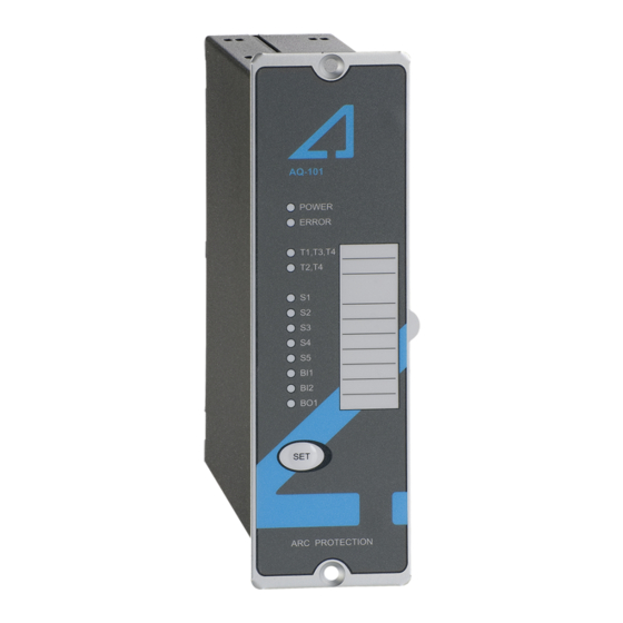
Figure. 3 - 1. Arc protection device AQ-101LV (left) and AQ-101DLV (right). The AQ-101LV is designed according to the latest protection relay standards and is therefore suitable for installations in rough environments. These include utilities and power plants (both traditional and renewable), various heavy industry applications (off-shore, marine, oil, gas, mining, steel, etc.) as well... - Page 10 4 Device features AQ-101LV is an arc flash protection device which can be applied to a variety of applications. It can be used on its own as a stand-alone device, or it can be a part of a more complex arc protection system by using binary inputs and outputs to connect multiple AQ 100 series devices together.
-
Page 11: Connections
-101LV V Instruction manual Version: 1.02 5 Connections The figures below depict the connections of AQ-101LV and AQ-101DLV. Please note that the SF relay is in the de-energized position. Figure. 5 - 2. Rear terminals of AQ-101LV. © Arcteq Relays Ltd... -
Page 12: Simplified Block Diagram
Instruction manual Version: 1.02 Figure. 5 - 3. Front terminals of AQ-101DLV. 5.1 Simplified block diagram The figure below presents the main components that can be found in both the AQ-101LV device and the AQ-101DLV variant. © Arcteq Relays Ltd IM00044... - Page 13 A A Q Q -101L -101LV V Instruction manual Version: 1.02 Figure. 5.1 - 4. Simplified block diagram of AQ-101LV and AQ-101DLV. © Arcteq Relays Ltd IM00044...
-
Page 14: Inputs
Figure. 5.2.1 - 5. Arc point sensor connections Both AQ-101LV and AQ-101DLV have four (4) arc point sensor channels: S1, S2, S3 and S4. You can connect a maximum of three (3) arc point sensors to each channel. When the arc protection system has been set up, point sensor connections are constantly monitored. -
Page 15: Outputs
AQ 100 series devices use these pulses to count the number of connected binary outputs. System self-supervision chapter for more information. NOTE! Please note that the binary ouputs are polarity-sensitive. 5.3.2 Trip relays Figure. 5.3.2 - 9. Trip relay connections © Arcteq Relays Ltd IM00044... -
Page 16: System Failure Relay
Figure. 5.4 - 11. Auxiliary power supply connection The auxiliary power supply voltage is 92….265 V AC/DC. Alternatively, the optional auxiliary power supply can be of 18…72 V DC. This choice must be specified when ordering. © Arcteq Relays Ltd IM00044... -
Page 17: Arc Sensors C Sensors
Installing a connection cable is simple as each end of the sensor has a detachable cover over the cable connectors. Please remember to reattach the cover once the wires have been installed. NOTE! The AQ-01 point sensor does no not t come with a connection cable! © Arcteq Relays Ltd IM00044... -
Page 18: Arc Light And Pressure Point Sensor Aq-02
AQ-07 sensors can be ordered in pre-manufactured lengths of 3…50 meters (3 m, 5 m, 10 m, 15 m, 20 m, 25 m, 30 m, 35 m, 40 m, 45 m, 50 m). © Arcteq Relays Ltd IM00044... -
Page 19: Arc Light Fiber Optic Loop Sensor Aq-08
If necessary, the ends of an AQ-07 cable can be ordered with heat shrinking tubing to avoid light detection outside the protected zone. The covered area can be one (1) or two (2) meters by default; if other lengths are required, please consult the Arcteq sales team. You can find the Contact and reference information page at the end of this manual. -
Page 20: Fiber Loop Sensors
2. Install protective covers in the holes to ensure the sensor cable remains unharmed by rough edges. 3. Run the sensor cable through the holes and along the protected area. Fasten it to the compartment walls with cable clips or some other appropriate anchoring method. © Arcteq Relays Ltd IM00044... - Page 21 Instruction manual Version: 1.02 4. Turn the black and blue receiver (“Rx”) and transceiver (“Tx”) screws counter-clockwise and plug in the sensor cable terminals. Then turn the screws clockwise to secure the terminals in their place. © Arcteq Relays Ltd IM00044...
-
Page 22: Operation And Config Tion And Configura Uration Tion
Please note that while the switch numbers and their functions are the same for both AQ-101LV and AQ-101DLV, in the DIN rail variant of the device the switches are "upside down" (that is, switch 1 is at the top of the DIP switch when normally switch 8 is at the top)! Figure. -
Page 23: Scheme Selection
Figure. 7.1.1 - 16. DIP switches used for selecting the logic scheme. 7.1.2 Available logic schemes The schemes described below are the most commonly used ones for AQ-101LV devices. However, additional schemes are also available; please contact your nearest Arcteq representative for more information on those schemes. - Page 24 The tripping criterion can be selected to be light only (L>) or both light and current (L> + I>). 2) If the blocking function (SW1: 5) is ON, the activation of BI1 blocks activation. © Arcteq Relays Ltd IM00044...
- Page 25 2) If the blocking function (SW1: 5) is ON, the activation of BI2 blocks activation. NOTE! In this scheme, the binary input BI1 is used as the input for resetting latched trip relays and LEDs. © Arcteq Relays Ltd IM00044...
- Page 26 The tripping criterion can be selected to be light only (L>) or both light and current (L> + I>). 2) If the blocking function (SW1: 5) is ON, the activation of BI2 blocks activation. © Arcteq Relays Ltd IM00044...
- Page 27 The tripping criterion can be selected to be light only (L>) or both light and current (L> + I>). 2) If the blocking function (SW1: 5) is ON, the activation of BI1 blocks activation. © Arcteq Relays Ltd IM00044...
-
Page 28: Push Button (Set)
1. Setting up the system (also known as auto-configuration) 2. Resetting the indicator LEDs 3. Resetting latched outputs 4. Checking the input connections Figure. 7.2 - 23. The "SET" push button on the device's front panel. © Arcteq Relays Ltd IM00044... -
Page 29: System Setup (Auto-Configuration)
7.3 LED indicator functions Both the AQ-101LV and its AQ-101DLV variant have twelve (12) indication LEDs on the device's front panel.. Apart from the "Power" and "Error" LEDs, the user can write their own identifications for each of the remaining LEDs on the text insert located in the transparent pocket next to the LEDs. -
Page 30: Led Operations Guide
-101LV V Instruction manual Version: 1.02 7.4 LED operations guide The table below describes the function of each indicator LED in detail. Table. 7.4 - 4. LED operations of AQ-101LV and AQ-101DLV. LED name LED name Light off ht off... -
Page 31: Sy Y St Stem Self-Super 8 S Em Self-Supervision Vision
The device goes into Error mode, if a DIP switch setting is changed after the system setup procedure has been performed. However, the configured (stored) settings are still valid and the device is still operational. © Arcteq Relays Ltd IM00044... - Page 32 A A Q Q -101L -101LV V Instruction manual Version: 1.02 9 Wiring example Figure. 9 - 24. Example wiring diagram for AQ-101LV and AQ-101DLV. © Arcteq Relays Ltd IM00044...
-
Page 33: Dimensions And Installa Imensions And Installation Tion
Instruction manual Version: 1.02 10 Dimensions and installation AQ-101LV can be either door-mounted or panel-mounted in a standard 19 inch rack. The device's dimensions (without PCBs) are as follows: • Height: 157 mm (6.18 in) • Width: 50 mm (1.97 in) •... - Page 34 Figure. 10 - 26. Dimensions of the DIN rail variant of the device. The following image illustrates how a device is installed into a cut-out. Please note that as AQ-101LV is narrower than the device in the image, they are connected to the cut-out panel by a single screw on both the top and the bottom of the front panel instead of the two depicted below.
-
Page 35: Testing Esting
10. Verify that no trip has occured and only the indicator LED of the sensor activation is lit. 11. If you are using the BO1 signal and have configured it to send light information, verify that it is activated. 12. Press the SET SET push button to reset all indications and latches. © Arcteq Relays Ltd IM00044... -
Page 36: Testing The Cbfp Function
If you want to have more information of these tests, please refer to the routine test reports sent with the AQ-101 device and/or consult your nearest Arcteq representative for the type test reports. - Page 37 A A Q Q -101L -101LV V Instruction manual Version: 1.02 © Arcteq Relays Ltd IM00044...
-
Page 38: Tr R Oubleshoo 12 T Oubleshooting Ting
Tripping might require overcurrent signal simultaneously with light signal. The trip relay does not operate even when the Check the DIP switch settings (see the DIP switch settings chapter for sensor is activated. more information). © Arcteq Relays Ltd IM00044... -
Page 39: Technic Echnical Da Al Data Ta
- make-and-carry for 3 s 16 A - make-and-carry for 0.5 s 30 A Breaking capacity DC* 40 W (0.36 A at 110 V DC) Contact material AgNi 90/10 *) When the time constant L/R = 40 ms. © Arcteq Relays Ltd IM00044... -
Page 40: Binary Output(S)
50,000 lux Pressure threshold (fixed) 0.2 bar above ambient pressure Pressure measuring accuracy ±1.8 % (of full scale) Detection radius 180º Mechanical protection IP 20 Sensor cable specification Shielded twisted pair 0.75 mm (AWG: 18) © Arcteq Relays Ltd IM00044... -
Page 41: Fiber Optic Loop Sensors
360º Bending radius 1 cm Operating temperature –40…+125 ºC 13.9 Disturbance tests Table. 13.9 - 17. Technical data for the disturbance tests. Electromagnetic compatibility test CE-approved and tested according to EN 50081-2 and EN 50082-2 © Arcteq Relays Ltd IM00044... - Page 42 Protection: - front IP 50 - back IP 20 50 × 157 × 160 mm Device dimensions (W × H × D) 145 × 109 × 34 mm (the DIN rail variant) Weight 0.7 kg © Arcteq Relays Ltd IM00044...
- Page 43 A A Q Q -101L -101LV V Instruction manual Version: 1.02 14 Ordering information AQ-101LV point sensor device (panel mounted) AQ-101DLV point sensor device (DIN rail mounted) © Arcteq Relays Ltd IM00044...
- Page 44 Accessories Order code Description Note Manufacturer AQX006 Wall mounting bracket For AQ-103 and AQ-110x variants (MV and LV). Arcteq Ltd. AQX016 Wall mounting bracket For AQ-101, AQ-101S and AQ-102 devices (MV and LV). Arcteq Ltd. © Arcteq Relays Ltd IM00044...
- Page 45 Arcteq Relays Ltd. Visiting and postal address Kvartsikatu 2 A 1 65300 Vaasa, Finland Contacts Phone: +358 10 3221 370 Website: arcteq.fi Technical support: support.arcteq.fi +358 10 3221 388 (EET 9:00 – 17.00) E-mail (sales): sales@arcteq.fi © Arcteq Relays Ltd IM00044...
Need help?
Do you have a question about the AQ-101LV and is the answer not in the manual?
Questions and answers