Table of Contents
Advertisement
Quick Links
Advertisement
Table of Contents

Related Manuals for Arcteq AQ-103LV


Summary of Contents for Arcteq AQ-103LV
- Page 1 AQ-103LV Arc flash protection unit Instruction manual...
-
Page 2: Table Of Contents
11.2.1. Trip relays ....................... 38 11.2.2. Binary output(s) ...................... 38 11.2.3. High-speed output(s) ....................38 11.2.4. System failure relay....................38 11.3. Binary inputs........................39 11.4. Auxiliary voltage........................ 39 11.5. Sensors ..........................39 11.6. Disturbance tests......................40 © Arcteq Relays Ltd... - Page 3 11.10. Casing and packaging ....................41 12. Or 12. Ordering inf dering informa ormation tion .............................................. 42 13. Contact and r 13. Contact and re e f f er erence inf ence informa ormation tion...................................... 43 © Arcteq Relays Ltd...
- Page 4 Nothing contained in this document shall increase the liability or extend the warranty obligations of the manufacturer Arcteq Relays Ltd. The manufacturer expressly disclaims any and all liability for any damages and/or losses caused due to a failure to comply with the instructions contained herein or caused by persons who do not fulfil the aforementioned requirements.
- Page 5 A A Q Q -103L -103LV V Instruction manual Version: 1.00 Copyright Copyright © Arcteq Relays Ltd. 2020. All rights reserved. © Arcteq Relays Ltd...
- Page 6 A A Q Q -103L -103LV V Instruction manual Version: 1.00 1. Manual revision notes R R e e vision vision 1.00 1.00 Date September 2020 Changes - The first revision of the manual. © Arcteq Relays Ltd...
-
Page 7: Abbr Bbre E Via Viations Tions
NC – normally closed NO – normally open PCB – printed circuit board QD – quenching device RF – radio frequency Rx – receiver SAS – standard arc scheme SF – system failure Tx – transceiver μP - microprocessor © Arcteq Relays Ltd... -
Page 8: General
The AQ-103LV device is designed according to the latest protection relay standards and it is therefore suitable for installations in rough environments. These include utilities and power plants (both traditional and renewable), various heavy industry applications (oil, gas, mining, steel, etc.) as well as commercial... - Page 9 A A Q Q -103L -103LV V Instruction manual Version: 1.00 Figure. 3.1. - 1. Dimensions of the device. The image below presents the dimensions of the cut-put need for mounting the unit on a panel. © Arcteq Relays Ltd...
- Page 10 A A Q Q -103L -103LV V Instruction manual Version: 1.00 Figure. 3.1. - 2. Cut-out for panel-mounting a unit. The following image illustrates how the unit is installed into a cut-out: © Arcteq Relays Ltd...
-
Page 11: Wiring
A A Q Q -103L -103LV V Instruction manual Version: 1.00 Figure. 3.1. - 3. Installing a unit into a cut-out. 3.2. Wiring © Arcteq Relays Ltd... - Page 12 A A Q Q -103L -103LV V Instruction manual Version: 1.00 Figure. 3.2. - 4. Wiring diagram for AQ-103LV. © Arcteq Relays Ltd...
-
Page 13: Unit Features
3.3. Unit features AQ-103LV is a multipurpose arc flash protection unit and can be applied to a variety of applications. It can be used on its own as a stand-alone unit, or it can be a part of a more complex arc protection system through the binary bus. -
Page 14: Simplified Block Diagram
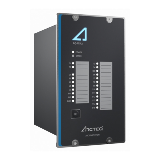
• twenty-five (25) indication LEDs • one (1) push-button. Figure. 3.3. - 6. Arc protection unit AQ-103LV. 3.4. Simplified block diagram The figures below present the main components of the AQ-103LV variants (the basic unit and the Modbus unit). © Arcteq Relays Ltd... - Page 15 A A Q Q -103L -103LV V Instruction manual Version: 1.00 Figure. 3.4. - 7. Simplified block diagram of AQ-103LV. © Arcteq Relays Ltd...
- Page 16 A A Q Q -103L -103LV V Instruction manual Version: 1.00 Figure. 3.4. - 8. Simplified block diagram of the AQ-103LV Modbus variant. © Arcteq Relays Ltd...
-
Page 17: Operation And Config Tion And Configura Uration Tion
4. Operation and configuration 4.1. LED indicator functions Both variants of the AQ-103LV unit have twenty-five (25) indication LEDs. Apart from the “Power” and “Error” LEDs, the user can write their own identifications for each of the remaining LEDs on the text insert sheet located in the transparent pockets next to the LEDs. -
Page 18: Push-Button (Set)
You can reconfigure a unit with more connections at any time without the wait and without having to move one of the DIP switches. 4.3.2. Reset All LED indications and latched trip relays can be reset by pressing the SET SET push-button for one second. © Arcteq Relays Ltd... -
Page 19: Input Connection Check
The channel operates as the arc quenching system control. (S5: Fiber Selects how the sensor as the fiber loop sensor The Tx terminal of S5 sends a test pulse signal to the loop channel S5 is used. function. quenching system. or or AQD) © Arcteq Relays Ltd... -
Page 20: Scheme Selection
4.4.2. Available logic schemes Below you can see descriptions of all the logic schemes available to the AQ-103LV unit. The basic logic is the same in all the logic schemes: BO1 and BI2 are always tripped by light (L>), whereas BI1 is always tripped by overcurrent (I>). - Page 21 The sensors S1 and S2 do not activate the AQD control. All sensors trip all trip relays (T1–T4) as well as the high-speed output (HSO). When the blocking function is selected, it prevents all tripping activations apart from LED activations. © Arcteq Relays Ltd...
- Page 22 (L>) or both light and current (L> + I>). When the current input function (SW1: 8) is OFF, the relay must receive both current and light signals simultaneously to be able to trip. © Arcteq Relays Ltd...
-
Page 23: Non-Volatile Memory
This feature is especially important if tripping causes the unit to lose its auxiliary power. The non-volatile memory does not require a power supply to maintain the information and it retains the settings and the indications permanently without power. © Arcteq Relays Ltd... -
Page 24: Arc Sensors C Sensors
Please remember to reattach the cover once the wires have been installed. NOTE! The AQ-01 point sensor does no not t come with a connection cable! © Arcteq Relays Ltd... -
Page 25: Arc Light And Pressure Point Sensor Aq-02
20 m, 25 m, 30 m, 35 m, 40 m). It is not recommended to cut or splice the cable on-site. However, if cutting or splicing is necessary due to the cable breaking, please contact your nearest Arcteq representative for instructions. -
Page 26: Arc Light Fiber Optic Loop Sensor Aq-07
When requested, the ends of an AQ-07 cable can be covered with black rubber to avoid light detection outside the protected zone (see the figure below). The covered area can be as large or small as necessary. For more information, please consult your nearest Arcteq representative. Figure. 5.4. - 13. AQ-07 sensor with covered ends. -
Page 27: Arc Light Fiber Optic Loop Sensor Aq-08
It is not recommended to cut or splice the cable on-site. However, if cutting or splicing is necessary due to the cable breaking, please contact your nearest Arcteq representative for instructions. The fixed light intensity threshold of an AQ-08 sensor is 8,000 lux. The sensor does not require further settings by the user. -
Page 28: Connecting Sensors
Please note that AQ-07 and AQ-08 glass fibers can be covered with additional tubing, if the fiber sensor's placing requires the blocking of unwanted light activation. For more detailed instructions on both the installation and the tubing processes, please refer to the "Connecting sensors" chapter in the AQ-0x instruction booklet (arcteq.fi/downloads). © Arcteq Relays Ltd... -
Page 29: Modbus Communic Tion
Modbus map Figure. 6. - 15. The Modbus map. © Arcteq Relays Ltd... -
Page 30: Sy Y St Stem Self-Super 7. S Em Self-Supervision Vision
The unit goes into SF alarm mode, if a DIP switch setting is changed after the system setup procedure has been performed. However, the configured (stored) settings are still valid and the unit is still operational. © Arcteq Relays Ltd... -
Page 31: Connections
A A Q Q -103L -103LV V Instruction manual Version: 1.00 8. Connections Figure. 8. - 16. Rear terminals of the AQ-103(LV) basic variant. Figure. 8. - 17. Connections of the AQ-103(LV) basic variant (with SF in de-energized position). © Arcteq Relays Ltd... -
Page 32: Outputs
8.1. Outputs 8.1.1. Trip relays This unit has four (4) integrated trip relays for tripping circuit breakers according to the scheme selection. Their type is normally open (NO). Optionally, T3 can be selected as normally closed (NC). © Arcteq Relays Ltd... -
Page 33: High-Speed Output(S)
The unit can have fifteen (15) sensor channels: fourteen (14) point sensor channels are included by default, and you can opt to have S5 be a fiber optic loop channel. Please note that unlike other AQ-100 series units, AQ-103 and AQ-103LV can only have one sensor in each sensor channel! © Arcteq Relays Ltd... -
Page 34: Binary Inputs
For more information on sensors, please refer to the “Arc sensors” chapter as well as to the AQ-0x instruction booklet which can be found on Arcteq's website (https://www.arcteq.fi/downloads/). 8.2.2. Binary inputs The unit contains two (2) binary inputs, BI1 and BI2. -
Page 35: Testing Esting
10. Activate the camera flash within 30 cm (12 inches) of the point sensor unit but do not activate the binary input used for the overcurrent condition (I>). 11. Verify that no trip has occured and only the indicator LED of the sensor activation is lit. © Arcteq Relays Ltd... -
Page 36: Testing The Unit Operation Time
If you want to have more information of these tests, please refer to the routine test reports sent with the AQ-103(LV) unit and/or consult your nearest Arcteq representative for the type test reports. - Page 37 A A Q Q -103L -103LV V Instruction manual Version: 1.00 © Arcteq Relays Ltd...
-
Page 38: Tr R Oubleshoo 10. T Oubleshooting Ting
Check the DIP switch settings (see the "DIP switch settings" chapter for more the sensor is activated. information). The system gives an alarm that cannot be Check that each sensor channel only has one sensor connected to it. cleared or installed. © Arcteq Relays Ltd... -
Page 39: Technic Echnical Da Al Data Ta
- make and carry for 0.5 s 15 A Breaking capacity DC* 1 A/110 W Contact material Semiconductor *) When the time constant L/R = 40 ms. 11.2.4. System failure relay Number of SF relays Rated voltage 250 V AC/DC © Arcteq Relays Ltd... -
Page 40: Binary Inputs
200 m Operating temperature –20…+85 ºC AQ-02 point sensor 8,000 lux Light intensity threshold 25,000 lux 50,000 lux Pressure threshold (fixed) 0.2 bar above ambient pressure Pressure measuring accuracy ±1.8 % (of full scale) Detection radius 180º © Arcteq Relays Ltd... -
Page 41: Disturbance Tests
1.2 mm Detection radius 360º Bending radius 1 cm Operating temperature –40…+125 ºC 11.6. Disturbance tests Electromagentic compatibility test CE-approved and tested according to EN 50081-2 and EN 50082-2 Emission Conducted (EN 55011, class A) 0.15…30.00 Hz © Arcteq Relays Ltd... - Page 42 - front IP 52 - back IP 20 Dimensions (W × H × D): - device 102 × 177 × 162 mm - package 230 × 120 × 210 mm 1.2 kg Weight 1.5 kg (with package) © Arcteq Relays Ltd...
- Page 43 A A Q Q -103L -103LV V Instruction manual Version: 1.00 12. Ordering information AQ-103LV arc flash protection unit AQ-0x point sensors AQ-0x fiber optic loop sensors Accessories Order code Description Note Manufacturer AQX099 Wall bracket For AQ-101, AQ-101S and AQ-102 units (MV and LV).
- Page 44 Manufacturer Arcteq Relays Ltd. Visiting and postal address Kvartsikatu 2 A 1 65300 Vaasa, Finland Contacts Phone: +358 10 3221 370 Fax: +358 10 3221 389 Website (general): arcteq.fi Website (technical support): support.arcteq.fi E-mail (sales): sales@arcteq.fi © Arcteq Relays Ltd...
Need help?
Do you have a question about the AQ-103LV and is the answer not in the manual?
Questions and answers