Table of Contents
Advertisement
Quick Links
Advertisement
Table of Contents

Subscribe to Our Youtube Channel
Related Manuals for Arcteq AQ-101S


Summary of Contents for Arcteq AQ-101S
- Page 1 AQ-101S Arc flash protection unit Instruction manual...
-
Page 3: Table Of Contents
11.4 Binary inputs........................35 11.5 Trip relays .......................... 36 11.6 Binary output(s) ......................... 36 11.7 System failure relay......................36 11.8 Sensors ..........................37 11.9 Disturbance tests....................... 37 11.10 Voltage tests........................38 11.11 Mechanical tests......................38 © Arcteq Relays Ltd IM00007... - Page 4 11.13 Casing..........................38 12 Or 12 Ordering inf dering informa ormation tion ..............................................39 13 Contact and r 13 Contact and re e f f er erence inf ence informa ormation tion......................................40 © Arcteq Relays Ltd IM00007...
- Page 5 Nothing contained in this document shall increase the liability or extend the warranty obligations of the manufacturer Arcteq Relays Ltd. The manufacturer expressly disclaims any and all liability for any damages and/or losses caused due to a failure to comply with the instructions contained herein or caused by persons who do not fulfil the aforementioned requirements.
- Page 6 A A Q Q -101S -101S Instruction manual Version: 2.01 Copyright Copyright © Arcteq Relays Ltd. 2021. All rights reserved. © Arcteq Relays Ltd IM00007...
-
Page 7: Document Inf
- The IP classification of point sensors updated. - The AWG value updated. - "Disturbance tests" table reformatted. - Order code images updated. - The number for Arcteq's technical support added to the reference information. © Arcteq Relays Ltd IM00007... -
Page 8: Abbr Bbre E Via Viations Tions
NO – normally open PCB – printed circuit board QD – quenching device RF – radio frequency Rx – receiver SAS – standard arc scheme SF – system failure Tx – transceiver μP - microprocessor © Arcteq Relays Ltd IM00007... -
Page 9: General
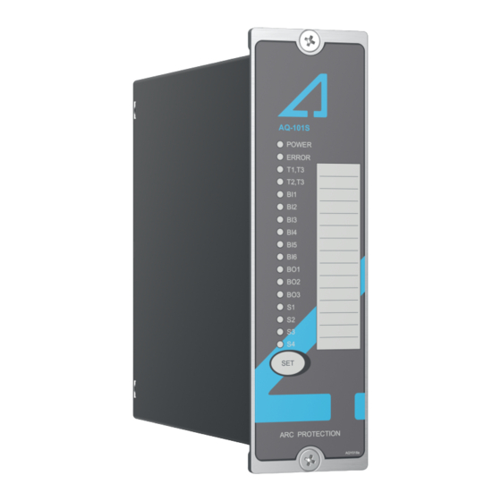
3.1 Unit features AQ-101S is a multipurpose arc flash protection unit and it can be applied to a variety of applications that require a large amount of data communication. It can be used on its own as a stand-alone unit, or it can be a part of a more complex arc protection system through a binary bus. -
Page 10: Dimensions And Installation
Instruction manual Version: 2.01 3.2 Dimensions and installation AQ-101S can be either door-mounted or panel-mounted in a standard 19 inch rack. The unit's dimensions (without cards) are as follows: • Height: 157 mm (6.18 in) • Width: 50 mm (1.97 in) •... - Page 11 Version: 2.01 The following image illustrates how a unit is installed into a cut-out. Please note that as AQ-101S is narrower than the unit in the image, it is connected to the cut-out panel by a single screw on both the top and the bottom of the front panel instead of the two depicted below.
-
Page 12: Simplified Block Diagram
A A Q Q -101S -101S Instruction manual Version: 2.01 3.3 Simplified block diagram The figure below presents the main components of the AQ-101S unit. Figure. 3.3 - 4. Simplified block diagram of AQ-101S. © Arcteq Relays Ltd IM00007... -
Page 13: Wiring
Please note that the latching (or non-latching) of trip relays T1 and T2 is determined with the DIP switch (SW1:6). The trip relay T3 is always latched. The binary output BO1 is always non-latched! 3.4 Wiring Figure. 3.4 - 5. Wiring diagram for AQ-101S. Station battery AQ-101S Uaux L>... -
Page 14: Operation And Config Tion And Configura Uration Tion
4 Operation and configuration 4.1 LED indicator functions The AQ-101S unit has seventeen (17) indication LEDs. Apart from the "Power" and "Error" LEDs, the user can write their own identifications for each of the remaining LEDs on the text insert located in the transparent pocket next to the LEDs. -
Page 15: Push Button (Set)
After this, you must wait one minute before you begin the new auto- configuration sequence. You can reconfigure a unit with more connections at any time without the wait and without having to move one of the DIP switches. © Arcteq Relays Ltd IM00007... -
Page 16: Reset
The DIP switches are located at the back of the unit for easy access. The figure below presents the DIP switch numbering, and the table below that gives a detailed description of the settings. Figure. 4.4 - 7. DIP switch diagram. © Arcteq Relays Ltd IM00007... -
Page 17: Scheme Selection
For detailed instructions on each of the available schemes please refer to the AQ-SAS™ booklet (can be found at arcteq.fi/downloads/). Please note that there are four booklets: two are for schemes based on IEC standards (MV and LV versions) and the other two for schemes based on ANSI standards (MV and LV versions). - Page 18 The binary input BI3 receives overcurrent information from the incoming feeder of a connected AQ-110P unit. The binary output BO1 sends light information to the incoming feeder of a connected AQ-110P unit when AQ-101S detects any arc fault.
- Page 19 The binary outputs BO1, BO2 and BO3 send arc fault information to the incoming feeder units and the intermediate units. You can find a more detailed description of this scheme in the AQ-SAS booklet. Figure. 4.4.2 - 11. The logic diagram of SS:2. © Arcteq Relays Ltd IM00007...
- Page 20 The binary outputs BO1, BO2 and BO3 send arc fault information to the incoming feeder units and the intermediate units. You can find a more detailed description of this scheme in the AQ-SAS booklet. © Arcteq Relays Ltd IM00007...
- Page 21 A A Q Q -101S -101S Instruction manual Version: 2.01 Figure. 4.4.2 - 14. The logic diagram of SS:3. Figure. 4.4.2 - 15. The DIP switch settings for SS:3. Figure. 4.4.2 - 16. The trip logic matric of SS:3. © Arcteq Relays Ltd IM00007...
- Page 22 BO1 and BO3 represent the arc fault detected at both main busbar sections. You can find a more detailed description of this scheme in the AQ-SAS booklet. Figure. 4.4.2 - 17. The logic diagram of SS:4. Figure. 4.4.2 - 18. The DIP switch settings for SS:4. © Arcteq Relays Ltd IM00007...
- Page 23 BO1 and BO3 send any detected arc fault information from the busbar and the section circuit breaker to both of the incoming AQ-110P units. You can find a more detailed description of this scheme in the AQ-SAS booklet. Figure. 4.4.2 - 20. The logic diagram of SS:5. © Arcteq Relays Ltd IM00007...
-
Page 24: Non-Volatile Memory
This feature is especially important if tripping causes the unit to lose its auxiliary power. The non-volatile memory does not require a power supply to maintain the information and it retains the settings and the indications permanently without power. © Arcteq Relays Ltd IM00007... -
Page 25: Arc Sensors C Sensors
Please remember to reattach the cover once the wires have been installed. NOTE! The AQ-01 point sensor does no not t come with a connection cable! © Arcteq Relays Ltd IM00007... -
Page 26: Arc Light And Pressure Point Sensor Aq-02
Yes (when the unit is Yes (when the unit is Yes (when the unit is A A Q Q -103 -103 equipped with the fiber equipped with the fiber equipped with the fiber option) option) option) © Arcteq Relays Ltd IM00007... -
Page 27: Connecting Sensors
4. Run the auto-configuration procedure. 5. Once the auto-configuration has been successfully completed, put the sensor covers back in place. For more detailed instructions, please refer to the "Connecting sensors" chapter in the AQ-0x instruction booklet (arcteq.fi/downloads). © Arcteq Relays Ltd IM00007... -
Page 28: Sy Y St Stem Self-Super 6 S Em Self-Supervision Vision
The unit goes into SF alarm mode, if a DIP switch setting is changed after the system setup procedure has been performed. However, the configured (stored) settings are still valid and the unit is still operational. © Arcteq Relays Ltd IM00007... -
Page 29: Applica A Tion Examples
In order to indicate the breaker's precise location, its position information is sent to the AQ-101S unit via the BI1 (main busbar) or BI2 (reserve busbar) binary input channel. The T1 trip contact is responsible for tripping the breaker. T3 gives synchronous information on the trip alarm. -
Page 30: Circuit Breaker Failure Protection
CBFP function. The CBFP function can be set to operate either on a 100-ms or a 150-ms delay (again, please refer to the "DIP switch settings" chapter for more information). © Arcteq Relays Ltd IM00007... -
Page 31: Connections
-101S Instruction manual Version: 2.01 8 Connections The figures below depict the connections of AQ-101S. Please note that the SF relay is in the de- energized position. Figure. 8 - 26. Rear terminals of AQ-101S. 8.1 Outputs 8.1.1 Trip relays This unit has two (2) integrated trip relays for tripping circuit breakers, namely T1 and T2. -
Page 32: Binary Outputs
8.2 Inputs 8.2.1 Arc sensor channels AQ-101S has four (4) arc point sensor channels: S1, S2, S3 and S4. You can connect a maximum of three (3) arc point sensors to each channel. For more information on sensors, please refer to the "Arc sensors" chapter as well as to the AQ-0x instruction booklet which can be found on Arcteq's website (https://www.arcteq.fi/downloads/). -
Page 33: Testing Esting
20 cm (12 inches) from the point sensor unit but do not activate the binary input used for the overcurrent condition (I>). 10. Verify that no trip has occured and only the indicator LED of the sensor activation is lit. © Arcteq Relays Ltd IM00007... -
Page 34: Testing The Cbfp Function
2. Connect one of the test set's outputs to a strong camera flash to initialize the flash and to configure the set's timer to start simultaneously with the flash. 3. Connect one of the AQ-101S unit's trip outputs (T1, T2, T3) to a test set input and configure the input to stop the timer. -
Page 35: Test Plan Example
A A Q Q -101S -101S Instruction manual Version: 2.01 9.5 Test plan example © Arcteq Relays Ltd IM00007... -
Page 36: Tr R Oubleshoo 10 T Oubleshooting Ting
Check the testing equipment, especially the camera flash intensity (see the "Testing" chapter for more information). The trip relay does not operate even when the Check the DIP switch settings (see the "DIP switch settings" chapter for sensor is activated. more information). © Arcteq Relays Ltd IM00007... -
Page 37: Technic Echnical Da Al Data Ta
Table. 11.3 - 9. Technical data for the relay auxiliary voltage (Uaux). 92…265 V AC/DC Auxiliary power supply 18…72 V DC (optional) Maximum interruption 100 ms Maximum power consumption 5 W, < 10 mΩ Standby current 90 mA © Arcteq Relays Ltd IM00007... -
Page 38: Binary Inputs
- make-and-carry for 3 s 16 A - make-and-carry for 0.5 s 30 A Breaking capacity DC* 40 W (0.36 A at 110 V DC) Contact material AgNi 90/10 *) When the time constant L/R = 40 ms. © Arcteq Relays Ltd IM00007... -
Page 39: Sensors
Other inputs and outputs: 4 kV, 5/50 ns Surge immunity Between wires: 2 kV, 1.2/50 µs (EN 61000-4-5, level 4) Between wire and earth: 4 kV, 1.2/50 µs RF electromagnetic field f = 80…1,000 MHz, 10 V/m (EN 61000-4-3, level 3) © Arcteq Relays Ltd IM00007... -
Page 40: Voltage Tests
Table. 11.13 - 20. Technical data for the device casing. Protection: - front IP 50 - back IP 20 Device dimensions (W × H × D) 50 × 177 × 161 mm Weight 0.7 kg © Arcteq Relays Ltd IM00007... - Page 41 Accessories Order code Description Note Manufacturer AQX006 Wall mounting bracket For AQ-103 and AQ-110x variants (MV and LV). Arcteq Ltd. AQX016 Wall mounting bracket For AQ-101, AQ-101S and AQ-102 units (MV and LV). Arcteq Ltd. © Arcteq Relays Ltd IM00007...
- Page 42 Arcteq Relays Ltd. Visiting and postal address Kvartsikatu 2 A 1 65300 Vaasa, Finland Contacts Phone: +358 10 3221 370 Website: arcteq.fi https://arcteq.fi/support-landing/ Technical support: +358 10 3221 388 (EET 8:00 – 16.00) sales@arcteq.fi E-mail (sales): © Arcteq Relays Ltd IM00007...
Need help?
Do you have a question about the AQ-101S and is the answer not in the manual?
Questions and answers