Advertisement
Quick Links
*47961351*
47961351
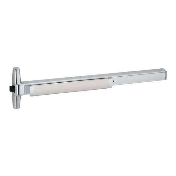
Rim Exit Device
Special tools needed:
#10-24, 1/4"-20 tap
Drill bits: #7, #25, 1/8", 1/4", 13/32", 1"
Devices covered by these instructions:
CD78 (Cylinder Dogging) Exit Device
QEL78/-F (Electric Latch Retraction) Exit
Dogging Key
(use with non-fire devices
to lock down pushbar)
1-877-671-7011
78 Rim
78 Rim Exit Device
78-F (Fire) Exit Device
Exit Device
Customer Service
www.allegion.com/us
Installation Instructions
Deviceated)
© Allegion 2024
Printed in U.S.A.
47961351 Rev. 04/24-a
Advertisement

Related Manuals for Allegion VON DUPRIN 78


Summary of Contents for Allegion VON DUPRIN 78
- Page 1 Deviceated) Exit Device Dogging Key (use with non-fire devices to lock down pushbar) Special tools needed: #10-24, 1/4"-20 tap Drill bits: #7, #25, 1/8", 1/4", 13/32", 1" Customer Service © Allegion 2024 Printed in U.S.A. 1-877-671-7011 www.allegion.com/us 47961351 Rev. 04/24-a...
-
Page 2: Screw Chart
SCREW CHART Screw Application Device Subassembly ³⁄4 #10-24 x ” (19 mm) Metal frame ¹⁄2 Wood frame #10 x 1 ” (38 mm) Wood screw 299 Strike 499F Strike Surface mount or Through bolts #10-24 x 1” (25 mm) ³⁄4 ”... - Page 3 Draw horizontal device and strike center lines ( C L ). Prepare 2 holes and install 2 screws. See “Screw Chart” on previous page for screw types and sizes * 39¹³⁄16” (101.1 cm) from finished floor For double doors with a mullion and strike already installed, use existing #10-24...
- Page 4 Prepare 4 center case mounting holes. Adjust tailpiece length if needed. Make sure tailpiece is installed at correct length for 1-3/4" thick or 2-1/4" thick door. If necessary, remove pine tree clip, rotate tailpiece, and reinstall pine tree clip. Four mounting holes 1-3/4"...
- Page 5 If necessary, install cylinder. If necessary, cut device. 1¹⁄2” (38 mm) recommended 1-1/8 - 1-1/4" (29-32 mm) Temporarily remove 1-3/8 - 1-1/2" anti-rattle clip (35-38 mm) Cover plate flush Attach center case to door.
- Page 6 Mark and prepare two (2) holes. Install required support screws and center case cover. Prepare holes after lock side of device is mounted and hinge side is leveled. SURFACE MOUNT Remove protective film from pushbar #10-24 ¹⁄8 ” (3 mm) x 1” (25 mm) Deep THROUGH BOLTS ¹⁄4 ”...
-
Page 7: 499F Strike Installation
499F STRIKE INSTALLATION 1. Prepare and install screws through two 2. Install strike hook and additional strike 3. Template aligns as shown. strike slots. screws. #7 Drill ¹⁄4 ” (6 mm)- Template 20 Tap (align on C L and 2 places against strike ¹³⁄32”... - Page 8 CD (CYLINDER DOGGING) OPTION Undog...
Need help?
Do you have a question about the VON DUPRIN 78 and is the answer not in the manual?
Questions and answers