Advertisement
*47986706*
47986706
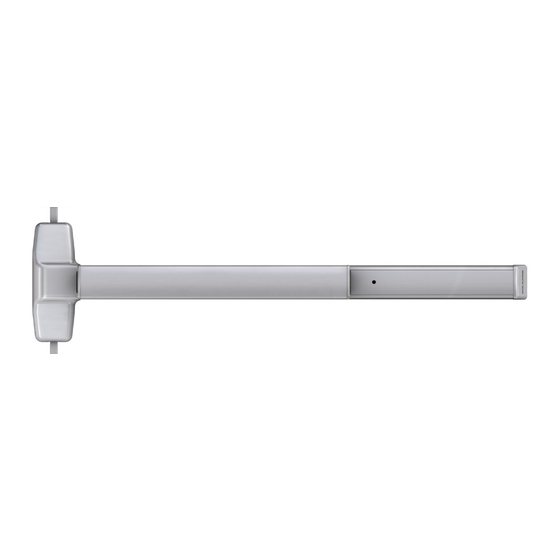
Surface Vertical Rod Exit Device
QEL7827/27-F (Electric Latch Retraction) Surface Vertical Rod Exit Device
Devices covered by these instructions:
7827 Surface Vertical Rod Exit Device
7827-F (Fire) Surface Vertical Rod Exit Device
CD7827 (Cylinder Dogging) Surface Vertical Rod Exit Device
Special tools needed:
5/64" hex wrench
#10-24 tap
Drill bits: #25, 1/8", 1/4", 5/16", 13/32"
1-877-671-7011
7827
Dogging Key
(use with non-fire devices
to lock down pushbar)
Customer Service
www.allegion.com/us
Installation Instructions
Index:
• Screw chart ............................. 2
• Preparation chart .................... 3
• Device installation ............... 4-6
• Cut top rod ............................. 7
• Install rod extension ................ 7
• Optional equipment ............... 8
• Cut device .............................. 8
© Allegion 2024
Printed in U.S.A.
47986706 Rev. 04/24-a
Advertisement
Table of Contents

Related Manuals for Allegion Von Duprin 7827 Series


Summary of Contents for Allegion Von Duprin 7827 Series
-
Page 1: Table Of Contents
• Install rod extension ....7 • Optional equipment ....8 • Cut device ......8 Special tools needed: 5/64" hex wrench #10-24 tap Drill bits: #25, 1/8", 1/4", 5/16", 13/32" Customer Service © Allegion 2024 Printed in U.S.A. 1-877-671-7011 www.allegion.com/us 47986706 Rev. 04/24-a... -
Page 2: Screw Chart
SCREW CHART Surface mount or #10-24 X 1” Sex bolts (1-3/4” door) Sex bolts (2-1/4” door) #10-24 X 1-1/2” Surface mount (wood) #10 x 1-1/4” Wood screw - Packaged with trim - 785 trims (1-3/4” door) #10-24 X 1-3/8” 785 trims (2-1/4” door) #10-24 X 1-7/8”... -
Page 3: Preparation Chart
PREPARATION CHART Go to instructions on next page before using Preparation Chart #25 Drill #10-24 Tap 1/8” Drill 5/16” Drill (device side) pilot 1” deep 13/32” Drill (trim side) 13/32” Drill thru #25 Drill #10-24 Tap 1/8” Drill pilot 1” deep *Use rod guide as a template to mark holes Center case - 4 holes... -
Page 4: Device Installation
Draw Horizontal Center Line ( ) and Assemble Adjust Tailpiece if Needed Device Template Make sure tailpiece is installed at correct length for 1-3/4" thick or 2-1/4" thick door. If necessary, remove pine tree clip, rotate tailpiece, Device and reinstall pine tree clip. template 1-3/4"... - Page 5 If Using a Cylinder with a Tailpiece, Prepare Device Install End Cap Bracket and End Cap and Cylinder a. Install tailpiece guide. Secure end cap bracket and end cap Tailpiece guide Trim output tailpiece Install Top Latch and Rod Install Trim (if using) and Secure Device Center Case to Door #325 sex latch...
- Page 6 Adjust Top Rod (Screw Rod Into or Out of Latch) Until Adjust Bottom Rod with Door Open (Top Latch Adjusted as Shown Retracted) With door With door open: closed: With door With door open: closed: Latch bolt stays Latch bolt retracted deadlocked (will not push in)
-
Page 7: Cut Top Rod
CUT TOP ROD 1. Measure amount to cut off rod as shown below. 2. Cut rod. Note: Rod cutting is required for doors shorter than 7’. Amount Drive out to cut off roll pin 3. Drill new hole. 1/8” dia. drill thru Use cut off *84”... -
Page 8: Optional Equipment
OPTIONAL EQUIPMENT - CONTINUED CD (CYLINDER DOGGING) Std. mortise cylinder 1. Remove mortise cylinder cam and reinstall in reverse (Figure 1). 2. Insert key and rotate cam to install the cylinder to the cover plate (Figure 2). 3. Remove key to slide cover plate in position in the mechanism case. Offset toward pushbar Cylinder...
Need help?
Do you have a question about the Von Duprin 7827 Series and is the answer not in the manual?
Questions and answers