Advertisement
Quick Links
*24908402*
24908402
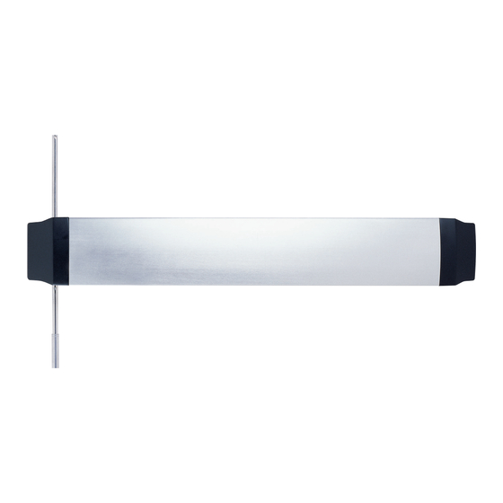
Recessed Exit Device
Devices covered by these instructions:
QEL94/9547/48 Concealed Vertical Rod Device (Panic and Fire)
QEL94/9547-LBR Concealed Vertical Rod Device (Fire)
Read All Warnings
Before Starting Installation!
QEL94/9547
Customer Service
1-877-671-7011
www.allegion.com/us
Installation Instructions
Instruction applies to devices built after
Dec. 2014. To identify device, see QEL
motor assembly as shown.
WARNING
Install in accordance with instructions or
device will not function.
CAUTION
For less bottom rod (LBR) devices, do not
cover the door gap at the auxiliary fire latch
with a door edge guard or similar product.
If edge guard is installed, remove it.
Index
• Warnings .......................... .......... 1
• Parts ........................................... 2
• General Information .................... 3
• Specifications ............................. 3
• Tools Needed ............................. 3
• Set Handing ............................... 3
• Installation .................................. 4
© Allegion 2018
Printed in U.S.A.
24908402 Rev. 10/18-c
Advertisement

Subscribe to Our Youtube Channel
Related Manuals for Allegion Von Duprin QEL9447


Summary of Contents for Allegion Von Duprin QEL9447
- Page 1 • General Information ....3 Read All Warnings • Specifications ......3 Before Starting Installation! • Tools Needed ......3 • Set Handing ....... 3 • Installation ........4 © Allegion 2018 Customer Service Printed in U.S.A. 24908402 Rev. 10/18-c 1-877-671-7011 www.allegion.com/us...
- Page 2 PARTS Ratchet release assembly Soffit strike Top latch assembly Top rod assembly Device QEL motor QEL cable End cap Bottom rod Dogging key assembly (panic devices only) End cap Bottom latch assembly Sill strike 2 of 16...
-
Page 3: General Information
GENERAL INFORMATION The QEL94/9547 Exit Device is designed to provide reduced pushpad projection and a unique appearance by embedding the device into the face of the door. These instructions assume that a factory-prepared door and frame are being used. Before starting installation, review "Warnings," "Parts," "Specifications," and "Tools Needed." SPECIFICATIONS Mechanical Electrical Load... - Page 4 PREPARE DOOR FOR TRIM (SKIP THIS STEP IF NOT USING TRIM) Drill through the four mounting holes and trim access hole at the latch side of the cutout. See trim installation instructions for hole sizes and locations. Latch Hinge side side PREPARE HOLE FOR RATCHET RELEASE PLUNGER a.
- Page 5 WIRE LX SWITCH (LX DEVICES ONLY) a. Connect field wiring to frame side of power transfer (Figure 3-1). b. See LX switch wiring information (Figure 3-2) for switch configuration. c. Connect LX switch wiring to door side of power transfer using crimp connectors. Unused wires should be insulated separately.
- Page 6 MOUNT DEVICE ON DOOR a. Mount device on door using supplied mounting screws (Figure 4-1). b. Center device in pocket, leaving an even gap all around the device. c. If outside trim is used, bolt through to trim (see Figure 4-2 and trim installation instructions). ⁵⁄₁₆"...
- Page 7 INSTALL TOP LATCH a. Rivet two-piece top rod together. Align holes according to door height (Figure 5-1). Rod length for a 7-foot door is approximately 38¹⁄₂”. Top rod sections are longer than bottom rod sections. b. Attach brackets to top latch, then thread rod assembly onto latch (Figure 5-2). c.
- Page 8 INSTALL BOTTOM LATCH (SKIP THIS STEP FOR LBR DEVICES) a. Repeat steps 6a through 6d for bottom rod and latch. Use hole 8 for most applications. Approximate rod length is 34¹⁄₂”. b. Press pushpad to retract latches. c. Hang door. INSTALL 338 SOFFIT STRIKE 8 of 16...
- Page 9 INSTALL SILL STRIKE OR THRESHOLD (SKIP THIS STEP FOR LBR) Strike ¹⁄₄" Carpet INSTALL RATCHET RELEASE ASSEMBLY #25 drill and #10-24 tap 2 places 9 of 16...
- Page 10 ADJUST TOP ROD a. Fully depress and hold pushpad. b. Set top latch in fully retracted (hold) position (Figure 10-1). c. Push down on center case connector, adjust rod length, and connect top rod (Figure 10-2). d. Verify that pushpad projection, when depressed, is between 1¹⁄₈”...
- Page 11 ADJUST BOTTOM ROD (SKIP THIS STEP FOR LBR DEVICES) a. Fully depress pushpad and release. Top latch should be in retracted position. b. Adjust bottom rod length by rotating rod so latch clears floor when door is open. Lengthen rod Shorten rod INSTALL RETAINER CLIPS ON TOP AND BOTTOM RODS AT CENTER CASE Center case...
- Page 12 TEST MECHANICAL DEVICE OPERATION a. Fully depress pushpad and push door open. b. Release pushpad. Latch bolts should remain retracted. ⁵⁄₁₆" pan head ⁵⁄₁₆" pan head machine screws machine screws c. Close door. Latch bolts should fully extend (⁵⁄₈" ± ¹⁄₁₆") and engage strikes. (quantity: 4) (quantity: 2) Figure 4-1...
- Page 13 INSTALL 900-2RS, 4RL, OR 4R OPTION BOARD(S) INTO POWER SUPPLY Review Available 900 series Plug Option Board Cable into Option Board Mounting any Available Option Connector Locations (Gray) PS902 1 Board PS904, 914 PS902 2 Boards PS906 3 Boards PS904 Secure Board(s) with Screws PS914 Notes: 1.
-
Page 14: Check Operation
CONNECT INPUT AND OUTPUT WIRES TO OPTION BOARD, 2RS SHOWN Sequential Mode - Typical Wiring Individual Mode - Typical Wiring Individual Mode - Typical Wiring Sequential Mode - Typical Wiring Input I1 will activate output 1 120/240 VAC Input I2 will activate output 2 120/240 VAC (PS900 PS900... - Page 15 LED - off 0VDC Latchbolt - retracted Mechanical dogging is engaged *For information about adjusting exit devices, you can find their installation instructions in the support area at www.allegion.com/us or call Technical Services at 1-877-671-7011 Output 2 LED Red on Device...
-
Page 16: Install End Caps
INSTALL END CAPS NOTE Make sure pushpad is in outward position before installing end caps. End cap End cap INSTALL AUXILIARY FIRE LATCH (LBR DEVICES ONLY) See installation instructions packaged with auxiliary fire latch kit. 16 of 16...
Need help?
Do you have a question about the Von Duprin QEL9447 and is the answer not in the manual?
Questions and answers