
Related Manuals for Allegion Von Duprin 98 Series


Summary of Contents for Allegion Von Duprin 98 Series
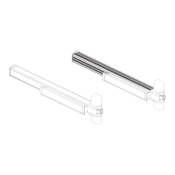
- Page 1 *911373-00* 98/99 911373-00 Rim Exit Device Installation Instructions #10-24 Dogging Key (use to lock down pushbar) Customer Service © Allegion 2015 Printed in U.S.A. 911373-00 Rev. 11/15-g 1-877-671-7011 www.allegion.com/us...
-
Page 2: Screw Chart
SCrew Chart Screw application Device Subassembly #10-24 x C\v” (19 mm) Metal frame #10 x 1Z\x” (38 mm) Wood screw Wood frame 299 Strike 499F Strike Surface mount or Sex bolts #10-24 x 1” (25 mm) 1C\v” (44 mm) door #10-24 x 1Z\x”... - Page 3 Draw horizontal device and strike center lines ( C L ). Prepare 2 holes and install 2 screws. See “Screw Chart” on previous page for screw types and sizes * 39ZC\zn” (101.1 cm) from finished floor For double doors with a mullion and strike already installed, use existing #10-24...
- Page 4 Prepare 4 center case mounting holes. If necessary, remove NL drive screw NL drive screw Factory installed on back of center case Four mounting holes With the NL drive screw removed, key locks and unlocks lever, knob, or thumb piece. For the trims listed below, REMOVE NL drive screw. 996L 696TP 990TP...
- Page 5 If necessary, cut device. Mark and prepare two (2) holes. Prepare holes after lock side of device is mounted and hinge side is leveled. SURFACE MOUNT 1Z\x” (38 mm) recommended #10-24 Z\,” (3 mm) x 1” (25 mm) Deep Temporarily remove anti-rattle clip SEX BOLTS Z\v”...
-
Page 6: 499F Strike Installation
Install required support screws and adjust strike as needed. center case cover. 299/299F Strike Shim as needed Remove protective film from pushbar C\zn” (5 mm) 299F Install strike support screw. METAL WOOD Z\,” (3 mm) x 1” (25 mm) Deep #10-24 499F StrIke INStaLLatION 1. -
Page 7: Optional Equipment
OPtIONaL equIPMeNt CD (Cylinder Dogging) Option Undog... - Page 8 OPtIONaL equIPMeNt 99-2 (Double Cylinder) Option Door Cutout for 99-2 “Double Cylinder” Option #8-18 x C\,” (10 mm) PPHSMS Wood Z\v” (6 mm) B\,” (16 mm) Deep #8-32 x B\zn” (8 mm) 1C\v” (44 mm) PPHMS 1Z\v” Z\,” (3 mm) R (32 mm) 4 places 1C\,”...
- Page 9 LHR shown, RHR opposite For cutouts on inside face of door, see exit device instructions Customer Service © Allegion 2014 Printed in U.S.A. 921265-00 Rev. 01/14-b 1-877-671-7011 www.allegion.com...
-
Page 10: Customer Service
• General Information ....• Specifications ......• Parts List ........• Warnings ........• Tools Needed ......• Installation ........• EL Wiring and Adjustment ..© Allegion 2014 Customer Service Printed in U.S.A. 941255-00 Rev. 01/14-c 1-877-671-7011 www.allegion.com/us... -
Page 11: General Information
GENERAL INFORMATION This kit converts 33/35, 33A/35A, and 98/99 series devices to electric latch (EL) retraction devices. Before beginning installation, review “Specifications,” “Parts List,” “Warnings,” and “Tools Needed.” SPECIFICATIONS Solenoid: Continuous duty: 24 VDC Current inrush: 16 A Current holding: 0.3 A PARTS LIST PS914 power supply with 900-2RS logic board... - Page 12 Remove device from door if installed (find correct device on page 3 or 4). Device and trim must be held securely while removing mounting screws to WARNING prevent device and trim from dropping to the floor. 98/99 Rim/Mortise Device Remove end cap and loosen or remove mounting bracket.
- Page 13 Continued from page 3. 33A/35A Rim Device Remove end cap and loosen or remove mounting bracket. Trim Remove 4 screws (remove trim also if it is not secure on door) 3327/3527 & 3327A/3527A Device Remove end cap and loosen or Detach rods (rod guides may also need removed) remove mounting bracket.
- Page 14 Disassemble device. 33/35 Device Remove push bar Remove mechanism case Baseplate assembly 33A/35A & 98/99 Device Remove push bar Used on 33A/35A only Remove mechanism case Remove screws from mechanism case Baseplate assembly 98/99 device center case shown...
- Page 15 Remove main link retaining ring and pin. Retaining ring Remove screws connecting center case to baseplate.
- Page 16 Install center case to new EL baseplate. Warning: Make sure retaining ring is secure in the pin groove. If retaining ring is not secure it could result in an exit device that will not allow exit. This is a serious safety issue. Note: For 33/35 series devices, place pin through front hole...
- Page 17 Reassemble device. 33/35 Device Push bar Install push bar guide Push bar guide Install mechanism case Note: Make sure crosspieces inside push bar Baseplate are placed in assembly slots in bellcranks. 33A/35A & 98/99 Device Install push bar Used on 33A/35A only Install...
- Page 18 Drill solenoid cable hole and install device to door. A. Drill 5/8” diameter hole in door centered between end cap bracket mounting holes. B. Deburr hole. C. Reattach device and trim to door. 5/8” Diameter cable hole End cap bracket mounting holes Note: The end cap bracket may be different than the one shown,...
- Page 19 Install cover plate and end cap. A. If cover plate has a dogging key hole, rotate cover plate so hole is near end cap for standard EL device and near pushbar for HD-EL device. B. Install anti-rattle spring. Cover plate C.
- Page 20 Continued from page 10. 9847/9947 Device or 3347A/3547A Device Latch bolt retracted Top latch bolt Open door and release top latch Depress pushbar and release. (flush with latch case) bolt as shown (Figure 11-1). Shown fully Make sure top latch bolt stays extended retracted as shown.
-
Page 21: Complete Wiring
Complete wiring. EL WIRING 12 AWG required for distances up to 200’ 14 AWG permitted for distances 0-100’ Potted Solenoid draws 16 A inrush current from PS914. circuit Solenoid Solenoid must be wired to a 900-2RS logic board: board If 900-2RS logic board, refer to instructions ELECTRICAL SPECIFICATIONS 44487056.
Need help?
Do you have a question about the Von Duprin 98 Series and is the answer not in the manual?
Questions and answers