Table of Contents
Advertisement
Quick Links
Overview
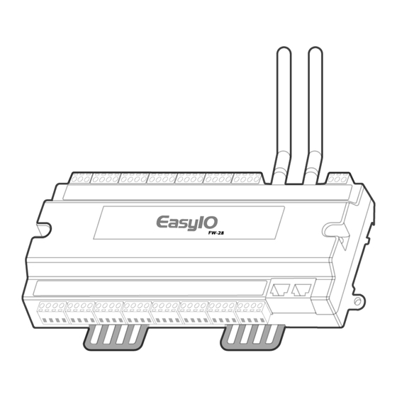
The FW-28 is an input/output controller with IP network,
Ethernet, and Wi-Fi connectivity. Use this guide to
complete the following tasks:
•
Understand the controller components
•
Mount the controller on a DIN rail or enclosure base
plate
Figure 1: FW-28 front view
Figure 2: FW-28 back and side view
FW-28 Quick Start Guide
•
Install the antennas
•
View a wiring diagram of the controller in a system
•
Connect to the controller with a LAN or Wi-Fi
connection
•
Connect to the controller with the Controller
Programming Tools (CPT) application
•
Connect to the controller's web server dashboard with
CPT Graphics
LIT-12013879
Version 1.0
2023-04-25
Advertisement
Table of Contents

Related Manuals for Johnson Controls FW-28


Summary of Contents for Johnson Controls FW-28
- Page 1 Install the antennas • View a wiring diagram of the controller in a system The FW-28 is an input/output controller with IP network, • Connect to the controller with a LAN or Wi-Fi Ethernet, and Wi-Fi connectivity. Use this guide to...
-
Page 2: Physical Dimensions
Mounting clips Physical dimensions Figure 3: FW-28 dimensions, mm (in.) Parts included Mounting locations to avoid • One FW-28 controller with removable terminal blocks • Areas with excessive moisture, corrosive fumes, or explosion vapors • Two Wi-Fi 2.4 Ghz, 2.2dBi antennas •... -
Page 3: Installing The Antennas
RP-SMA jacks, screw on the antennas in a clockwise direction. Note: For a secure connection hold the metal part of the RP-SMA male connector. A poor connection reduces reception when you tighten the antennas to the female RP-SMA jack. FW-28 Quick Start Guide... -
Page 4: Removing The Controller Cover
Use a Philips screwdriver to unscrew both of the top cover screws. Figure 9: Unscrewing the cover Hold both ends of the top cover and remove it. If the top cover is stuck, separate the cover with a flathead screwdriver. FW-28 Quick Start Guide... - Page 5 Use the correct electrostatic discharge precautions throughout installation, setup, and service to avoid damage to the controller and controller components. FW-28 Quick Start Guide...
- Page 6 FW-28 basic input, output, power, and serial device wiring setup Figure 11: FW-28 wiring guide Figure 12: 24 VAC Class 2 transformer power input Callout Description Power input 24 VAC or 24 VDC External pilot duty relay that the DO...
- Page 7 22 AWG copper stranded twisted wire up to Field device 100 m (328 ft) in length 20 AWG copper stranded twisted wire up to Controller 100 (328 ft) m in length UI terminal DO terminal COM terminal COM terminal Controller FW-28 Quick Start Guide...
- Page 8 However, when you need to ground the secondary of the 24 VAC transformer, make only one ground connection near the transformer. For more information, see the following figure. Figure 18: Transformer grounding FW-28 Quick Start Guide...
- Page 9 You can connect to your UI jumper setting controller with a device through Ethernet or though Wi-Fi. The FW-28 UI jumper includes 16 sets of UI and supports Note: Use the following procedures to set up both resistance and voltage field devices.
- Page 10 Primary network default IP address, address, subnet mask, default gateway you want: subnet mask, and gateway networksetup -setmanual "Ethernet" <new IP address> <subnet mask> <gateway> b. Enter the ping command, followed by the controller's IP address to confirm the connection. FW-28 Quick Start Guide...
- Page 11 No errors Green 1 Hz blinks 1 Hz blinks Normal operation Off steady Controller fault TXRX Yellow 1 Hz to 5 Hz 1 Hz to 5 Hz blinks Normal data communication blinks Off steady No data transmission FW-28 Quick Start Guide...
-
Page 12: Troubleshooting
0 V to 10 V output results in an Measure the output and verify that it matches the unwanted offset of up to 1 V. command. Disconnect the connected device and verify the The Common Reference is commanded value is present. incorrect. FW-28 Quick Start Guide... -
Page 13: Technical Specifications
Technical specifications Table 4: FW-28 UL input, output, and communication ratings Description Specification Terminal Power supply • 24 VAC, plus or minus 5% H and G • 24 VDC, plus 20% or minus 15% 12 VA, Class 2 Universal Voltage... - Page 14 Compliance Table 6: FW-28 Compliance North America: UL 916 Energy Management Equipment; FCC Class B, Part 15, Subpart C 15.247 This device contains licence-exempt transmitter(s)/receiver(s) that comply with Innovation, Science and Economic Development Canada’s licence-exempt RSS(s). This device complies with part 15 of the FCC Rules.
-
Page 15: Product Warranty
LANE GLENDALE, WI NO. 32 53209 NETHERLANDS MANCHESTER CHANGJIANG M40 2WL RD NEW UNITED DISTRICT KINGDOM WUXI JIANGSU PROVINCE 214028 CHINA Contact information Contact your local Johnson Controls representative: www.johnsoncontrols.com/locations Contact Johnson Controls: www.johnsoncontrols.com/ contact-us FW-28 Quick Start Guide... - Page 16 © 2023 Johnson Controls. All rights reserved. All specifications and other information shown were current as of document revision and are subject to change without notice. www.johnsoncontrols.com...
Need help?
Do you have a question about the FW-28 and is the answer not in the manual?
Questions and answers