Table of Contents
Advertisement
Quick Links
Windows are trademarks of Microsoft Corporation, U.S.A. and other countries.
Generally, company names and trade names described in this Instruction Manual are trademarks or registered
trademarks of the companies.
This Instruction Manual may not be copied or reproduced, in whole or part, without consent of KYOWA.
Copyright © Kyowa Electronic Instruments Co., Ltd. All rights reserved.
The contents of the Instruction Manual are subjected to change without prior notice.
INSTRUCTION MANUAL
MEMORY RECORDER/ANALYZER
Thank you for purchasing KYOWA's product EDX-3000A Memory
Recorder/Analyzer.
Read this Instruction Manual carefully in order to make full use of the high
performance capabilities of the product.
Do not use the product in methods other than described in this Manual.
This Manual only describes hardware operation of the EDX-3000A. For
Software operation, refer to the EDX-3000A Instruction Manual for
Software.
IM-A-767D December 2023
EDX-3000A
[FOR HARDWARE]
Advertisement
Table of Contents
Troubleshooting

Subscribe to Our Youtube Channel
Related Manuals for KYOWA EDX-3000A


Summary of Contents for KYOWA EDX-3000A
- Page 1 Generally, company names and trade names described in this Instruction Manual are trademarks or registered trademarks of the companies. This Instruction Manual may not be copied or reproduced, in whole or part, without consent of KYOWA. Copyright © Kyowa Electronic Instruments Co., Ltd. All rights reserved.
-
Page 2: Table Of Contents
PRIOR TO USE ································································································································ 2 SAFETY SYMBOLS ·························································································································· 2 LIMITED LIFE PARTS AND PREVENTIVE MAINTENANCE ·································································· 6 EDX-3000A REPLACEMENT BEFORE THE END OF SERVICE LIFE ······················································· 6 NOTATIONS USED IN THE INSTRUCTION MANUAL ··········································································· 7 OUTLINE OF PRODUCT ············································································································· 8 1-1 OUTLINE ································································································································... - Page 3 11-3 MONITOR ···························································································································· 46 11-4 DATA REPRODUCTION ········································································································· 47 11-5 CONFIGURATION ················································································································ 49 11-6 PRINT ································································································································· 49 12. EXTERNAL VIEWS ···················································································································· 50 12-1 MEMORY RECORDER/ANALYZER: EDX-3000A ······································································· 50 12-2 STRAIN/VOLTAGE MEASUREMENT CARD: CDV-40B ······························································· 51 12-3 REMOTE CONTROL UNIT: RCU-42A ······················································································ 51...
-
Page 4: Standard Accessories
This Manual contains operating instructions for the Memory Recorder/Analyzer EDX-3000A and CDV-40B hardware. STANDARD ACCESSORIES The following accessories are packed with the Memory Recorder/Analyzer EDX-3000A. When unpacking, check the contents to ensure that all accessories are enclosed. AC Power Cable: P-18 ·············································································· 1 3P-2P Conversion Adapter: CM-331F19 ·························································... -
Page 5: Safety Precautions
AC power outlet. ● Inflammable Environment To prevent the risk of fire and explosion, do not operate the EDX-3000A in area exposed to flammable gases, vapors, or dust. ● Abnormal Condition To prevent fire hazards, if smoke is emerging from the EDX-3000A, immediately turn OFF the power switch and disconnect the power cable from the AC power outlet to terminate the system operation. - Page 6 Use a tester or the like to measure the voltage between negative sides of the DC voltage and confirm that the voltage is approximately 0 V. Confirm that the voltage between the negative side of the DC voltage and the GND terminal of the EDX-3000A is approximately 0 V.
- Page 7 ● Do not use the EDX-3000A under poor conditions. Operate the EDX-3000A within the range of 100 to 240 VAC (50/60 Hz). The power supply used for the EDX-3000A should not experience an instantaneous power failure and be free from noise.
- Page 8 The battery can no longer be used and have to be replaced if it have been over discharged. In addition, if the EDX-3000A is to be stored for an extended period, The self-discharge rate and deterioration rate of the battery are closely related to the storage temperature.
-
Page 9: Limited Life Parts And Preventive Maintenance
EDX-3000A. Regardless of the replacement parts, the EDX-3000A itself gradually deteriorates with age. Before the expected service life is reached, consider replacing the EDX-3000A with a new one or the latest series as preventive maintenance. - 6 -... -
Page 10: Notations Used In The Instruction Manual
Certain notations are used as necessary to urge attention to information that requires special attention in the handling of the system, and to information provided for reference purposes. Examples of Notations. NOTE Essential precautions when handling the EDX-3000A. MEMO Reference items when handling the EDX-3000A. - 7 -... -
Page 11: Outline Of Product
The number of conditioner cards that can mount into the EDX-3000A is 8 and the number of channels is MAX. 64. In addition, the EDX-3000A can deal with various measurements since the EDX-3000A has many external I/O functions. -
Page 12: Controls And Indicators
Turn ON the MAIN POWER switch on the rear panel and press the “POWER” switch for 2 seconds or longer to turn ON the EDX-3000A. If you press the “POWER” switch for 2 seconds or longer with the EDX-3000A power ON state, the internal setting information is stored first and the EDX-3000A is turned OFF. - Page 13 J: BAL. switch Press the BAL switch for 1 second or longer to conduct balance. K: OPT. switch Can set the function of the “OPT. switch” with the EDX-3000A Control Software. L: USB connector USB 2.0 connector M: Handle Handle N: CH LED Indicates the status of channels.
-
Page 14: Rear
MAIN POWER switch to [○] side with the EDX-3000A ON or during shut down. Do not lay the Failure to observe these precautions may destroy the internal hard disk and prevent the EDX-3000A from starting again. C: Power connector for 15-inch display Dedicated power supply connector for the optional 15-inch display (EMON-30A). - Page 15 M: TRG OUT connector Outputs trigger signal when triggered. (H: 5 V,L: 0 V) N: CLK IN connector Used for operating the EDX-3000A with the external clock signal. (H: 2.0 to 5 V,L: 0 to 0.8 V) O: READY connector Outputs LOW level signal when recording and other than that, outputs HIGH level signal.
-
Page 16: Installing Edx-3000A
Supply AC power to the EDX-3000A with the attached AC power cable. Check the power supply voltage before connecting the power cable to the AC power outlet. The operating power supply voltage range of the EDX-3000A is 100 to 240 VAC. Always operate the EDX-3000A within the specified voltage range. -
Page 17: Connecting Sensor
If excessive noise is measured, ground the ground terminal of the bridge box or connect it to the GND terminal EDX-3000A, whichever results in less noise. ACOM and FG are common potentials. MEMO Refer to the Instruction Manual of measurement cards when using other cards. - Page 18 1) Use a tester or the like to measure the voltage between negative sides of the DC voltage and confirm that the voltage is approximately 0 V. 2) Confirm that the voltage between the negative side of the DC voltage and the GND terminal of the EDX-3000A is approximately 0 V.
- Page 19 NOTE When using a voltage and strain sensor input signals together in the same CDV-40B card, a cross talk may generate and display a waveform different from a sensor input waveform on the strain sensor connected channel. [The worst case] If the worst comes to the strain sensor input channel with the following conditions, a cross talk of 120 μm/m may generate.
-
Page 20: Connecting Digital Input Connector
Common Common 【Note】The signal common is used in common for bits 1 to 32, and is insulated from the casing and the power supply of the EDX-3000A. NOTE (*) The pin No. 17 is reserved pin. Do not connect anything. -
Page 21: Measuring
After connecting the sensor, turn ON (“|”) the MAIN POWER switch on the rear panel of the EDX-3000A. Then press the POWER switch on the front panel for 2 seconds to activate the EDX-3000A. For details of the conditioner settings and measuring condition settings, see the Instruction Manual for Software. -
Page 22: External Trigger "Trg In" "Trg Out
4-2-1 External Trigger “TRG IN” “TRG OUT” The EDX-3000A starts recording by inputting the external trigger input signal to the “TRG IN.” In addition, the EDX-3000A can supply the external trigger output signal from the “TRG OUT” to the external device. -
Page 23: External Clock "Clk In" "Clk Out
If a pulse signal supplied from the external device such as oscillator is input as the external clock input signal to the “CLK IN,” the pulse signal can be used as the sampling clock of the EDX-3000A. In addition, the EDX-3000A can supply the sampling clock of the EDX-3000A as the external clock output signal from the “CLK OUT”... - Page 24 ● Input a fixed clock (frequency does not change) to the external clock supplying to the EDX. ● It is necessary to supply the external clock while the EDX-3000A is measuring data. The EDX-3000A cannot start measuring data if the external clock is not supplied.
-
Page 25: Recording Signal "Ready
In addition, starting time and ending time of the READY signal delay for approx. 0.5 to 3 seconds than the “starting time” or “ending time” of the EDX-3000A. This amount of delay varies with the setting value of the trigger delay amount, size of the recording data, and CPU usage rage of the EDX-3000A. -
Page 26: Input/Output Timing Of Signals
Ex. 5 (TRG IN) Not use 100 Hz or more Note 1: Including start trigger of the complex trigger. Note 2: Select “Set Meas Mode Condition” – “Real Time Process” – “Recording moving image” in the EDX-3000A Software. - 23 -... - Page 27 = Approx. 2 to 3 sec. t1 = Approx. 0.5 sec. [Note] Note that the t1 and t2 vary with the setting value of the trigger delay amount, recording data size and CPU usage rate in the EDX-3000A. Ex. 2 Trigger mode:...
- Page 28 [Note] It is required that the time Tg (from the start trigger to end trigger) requires 1 cycle (Ts) of the sampling clock or more. Note that the t1 and t2 vary with the setting value of the trigger delay amount, recording data size and CPU usage rate in the EDX-3000A. Ex. 4 Trigger mode: Digital trigger (start trigger D1 = “1”, end trigger D1 =...
- Page 29 [Note] It is required that the time Tg (from the start trigger to end trigger) requires 1 cycle (Ts) of the sampling clock or more. Note that the t1 and t2 vary with the setting value of the trigger delay amount, recording data size and CPU usage rate in the EDX-3000A. - 26 -...
-
Page 30: Synchronous Operation
For synchronous operating the multiple EDX-3000A units, turn ON/OFF the EDX-3000A as follows. For turning ON the power, turn ON the EDX-3000A from the unit having the large ID No. to small ID No. (turn On the master EDX-3000A [ID No. 0] at last). In the following figure, turn ON the power as follows. - Page 31 Connect the monitor, key board, and mouse to every EDX-3000A and set the ID settings on the Set Environment dialog box. Be sure to set the first EDX-3000A as the “Synchronous master (ID No. 0) and set the remaining EDX-3000A units as the “Slave master (ID No.
-
Page 32: Online Control
4-4 ONLINE CONTROL Online control is a function for controlling the EDX-3000A from the control software DCS-100A that is installed in the external PC via the LAN interface. Connection diagram is shown as follows. Online control, stand alone type (EDX-3000A: 1) - Page 33 For synchronous operating the multiple EDX-3000A units, turn ON/OFF the EDX-3000A as follows. For turning ON the power, turn ON the EDX-3000A from the unit having the large ID No. to small ID No. (turn On the master EDX-3000A [ID No. 0] at last). In the following figure, turn ON the power as follows.
-
Page 34: Turning Off The Edx-3000A
4-5 TURNING OFF THE EDX-3000A After the measurement, press the POWER switch of the EDX-3000A for 2 seconds for turning OFF the EDX-3000A. The EDX-3000A automatically shuts off. After the shutdown finishes, turn OFF (“○”) the MAIN POWER switch on the rear panel. -
Page 35: For Built-In Battery Against Instantaneous Power Failure
3 minutes if the built-in battery becomes old or is not fully charged. Therefore, avoid using the EDX-3000A under conditions in which the power supply may be lost at any time. Contact KYOWA or our representatives when the built-in battery expired. -
Page 36: How To Charge
The MAIN POWER switch on the rear panel is ON (“|”). When the EDX-3000A is in the state a) or b) even if it is turned OFF, built-in battery is automatically charged and the CHARGE LED lights up in green. In addition, the charging is automatically finished after fully charged and the CHARGE LED flashes green. -
Page 37: Remote Control Unit
Always turn OFF the EDX-3000A before connecting the remote control unit RCU-42A. MEMO The remote controller incorporates a buzzer which emits same alarm of the EDX-3000A. You can hear the alarm from the remote controller even if it is difficult to hear from the EDX-3000A. -
Page 38: Recording Voice Memo
Total recording time of 1048 seconds (approx. 17 minutes), or Total recording times of 255 times The EDX-3000A can record voice memo up to satisfying the either 1) or 2). NOTE Data recording (REC) does not start by pressing the VOICE MEMO switch. -
Page 39: Troubleshooting
7. TROUBLESHOOTING If the EDX-3000A does not operate as expected or in a stable manner, examine the facts that may be causing such a condition before concluding that the system has failed. Items to be checked and countermeasures for various symptoms are described below. -
Page 40: Trobleshooting For Strain/Voltage Measurement Card Cdv-40B
・When using the strain gage, noise may be reduced by connecting the GND terminal of the EDX-3000A and the test specimen to which the strain gage is attached. See “3-3 CONNECTING SENSOR.” ・Is there an inverter motor, machining equipment, welder or AC power supply for power systems placed near the input cable for the EDX-3000A? If so, move the input cable apart from the power source. -
Page 41: Troubleshooting For Dynamic Strain Measurement Card Dpm-42B/A (-F), Dpm-42B-I
∙ Did you turn ON/OFF the EDX-3000A units in the correct order when synchronous operating them? Turn OFF the all EDX-3000A units, wait approx. 2 hours and turn ON the power again by referring to “4-3 SYNCHRONOUS OPERATION” and “4-4 ONLINE CONTROL.”... -
Page 42: Maintenance
The card is correctly replaced when you see the target CH LED applicable to the changed slot is lightning. The CH LED is OFF even after setting the measuring conditions when the EDX-3000A is not operate correctly. At this time, remove the card and reinsert the conditioner card once again. -
Page 43: Connector Pin Assignment Of Cdv-40B
9. CONNECTOR PIN ASSIGNMENT OF CDV-40B 9-1 CDV-40B CENTRALIZED CONNECTOR Pin No. Name Pin No. Name +BV -IN -BV +BV -IN -BV +BV -IN -BV +BV -IN -BV +BV -IN -BV Model: DN-50S +BV -IN Manufacture: Hirose -BV +BV -IN -BV +BV -IN... -
Page 44: Hardware Specifications
10. HARDWARE SPECIFICATIONS 10-1 OVERALL SPECIFICATIONS 1) Model Model Storage device Language (Internal disk) EDX-3000A-H Japanese EDX-3000A-HE English EDX-3000A-S Japanese EDX-3000A-SE English [Note] HDD: Hard Disk Drive SSD: Solid State Drive 2) Conditioner cards Strain/voltage/acceleration measurement card: CVM-40A, CVM-41A Strain/voltage measurement card:... - Page 45 0 to 40℃,20 to 80%RH (noncondensing) 17) Storage temperature range -20℃ to 60℃ 18) Vibration resistance EDX-3000A-H (E), EDX-3000A-S (E) 49.0 m/s (5 G), 5 to 55 Hz (when not operating) 29.4 m/s (3 G), 5 to 55 Hz (when operating) EDX-3000A-H (E) 9.8 m/s...
-
Page 46: Internal Conditioner Specifications
Conduct balance adjustment. 5.“OPT.”: Arbitrary function Arbitrary assign functions such as “Start monitoring”, “Input CAL”, etc. with the EDX-3000A Control Software. 6.“VOICE MEMO”: Used for recording voice. 3) Display The LED display allows the user to distinguish whether the data recording is in progress, data recording is paused, voice is being recorded or data recording has been stopped. -
Page 47: Software Specifications
11. SOFTWARE SPECIFICATIONS 11-1 MEASURING CONDITIONS 1) Channel conditions Measuring ON/OFF, measuring mode, range, high-pass filter, low-pass filter, balance ON/OFF, CAL range, CAL ON/OFF,calibration coefficient, offset, unit, channel name, measuring range, rated capacity, rated output, display digit (any display items can be selected) 2) Number of recordable Up to remaining disk space of built-in memory: data items... -
Page 48: Measuring Operation
256, 512, 1024, 2048, 4096, 8192 Number of analysis windows MAX. 8 Measuring conditions Measurement modes Manual mode, Manual mode (Set Record Data), Interval mode, Analog trigger mode 11-2-2 Saving file formats KYOWA standard file format (KS2) KS2 file version: 01.04 - 45 -... -
Page 49: Monitor
11-3 MONITOR 1) Y-Time graph X-axis indicates the time, and Y-axis the physical amount of measurement for a maximum of 16 channels. 1 to 4 graphs can be displayed on a window. 2) Y-Time (DIV) graph X-axis indicates the time, and Y-axis the physical amount of measurement for a maximum of 16 channels. -
Page 50: Data Reproduction
11-4 DATA REPRODUCTION 11-4-1 Recorded Data Display 1) Graph display 4 patterns of display condition can be set for a graph. Y-Time graph X-axis indicates the time, and Y-axis the physical amount of measurement for up to 16 channels. 1 to 4 graphs can be displayed on a window. X-Y graph Any 4 graphs can be plotted on X- and Y-axis. - Page 51 3) FFT Analysis Analysis type: Linear spectrum, power spectrum, cross spectrum, auto-correlation, cross-correlation, coherence, transfer function Window functions: OFF, Hanning, Hamming, Fejer, Blackman, Gaussian Number of analysis data 256, 512, 1024, 2048, 4096, 8192, 16384, 32768 Filter 12 steps of 1, 2, 5, 10, 20, 50, 100, 200, 500, 1000, 2000 Hz and FLAT No.
-
Page 52: Configuration
5) Filtering Digital filter: IIR filter for 4th order Butterworth characteristics (no phase delay and -6dB at the cutoff frequency) High-/low-pass filters FLAT to 500 kHz. (effective up to one-half of the sampling frequency) Mirroring 6) Differentiation/Integration No. of times of differentiation/integration (1, 2) and an engineering unit can be specified after processing. -
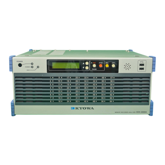
Page 53: External Views
12. EXTERNAL VIEWS 12-1 MEMORY RECORDER/ANALYZER: EDX-3000A - 50 -... -
Page 54: Strain/Voltage Measurement Card: Cdv-40B
12-2 STRAIN/VOLTAGE MEASUREMENT CARD: CDV-40B 12-3 REMOTE CONTROL UNIT: RCU-42A - 51 -...
Need help?
Do you have a question about the EDX-3000A and is the answer not in the manual?
Questions and answers