Table of Contents
Advertisement
Quick Links
This product is a copyrighted work of KYOWA ELECTRONIC INSTRUMENTS CO., LTD. All rights
reserved.
Copying or reproduction of this product, whether in part or whole, is strictly prohibited without permission.
The contents of this Manual are subject to change without prior notice.
DYNAMIC STRAIN METER CARD
DPM-42A/DPM-42A-F
I
NSTRUCTION MANUAL
Thank you for purchasing KYOWA's product DPM-42A/DPM-42A-F Dynamic Strain
Meter Card for EDX-2000A Memory Recorder/Analyzer.
Read this manual carefully to ensure the long life and reliability of the product.
The product should not be used in any manners other than as described in this Instruction
Manual.
IM-A-596B January 2024
for EDX-2000A
Advertisement
Table of Contents

Related Manuals for KYOWA DPM-42A


Summary of Contents for KYOWA DPM-42A
- Page 1 The product should not be used in any manners other than as described in this Instruction Manual. This product is a copyrighted work of KYOWA ELECTRONIC INSTRUMENTS CO., LTD. All rights reserved. Copying or reproduction of this product, whether in part or whole, is strictly prohibited without permission.
-
Page 3: Table Of Contents
CAUTION ..................................2 NOTATIONS USED IN THE INSTRUCTION MANUAL ..................3 1. OUTLINE OF THE PRODUCT ..........................4 1-1 OUTLINE OF THE DPM-42A (-1/-F/-F1) Card ....................4 1-2 OUTLINE OF THE DPM-42A-F (F1) ........................4 1-3 PRECAUTIONS FOR USING DPM-42A(-1/-F/-F1) ................... 5 1-4 PRECAUTIONS FOR USING DPM-42A-F(F1) .................... -
Page 5: Standard Accessories
EGG.1B.307.CLL (LEMO made) DPM-42A-F1 EGG.1B.307.CLL (LEMO made) NOTE The DPM-42A-1 and DPM-42A-F1 are not displayed in the EDX-2000A Application Software. The DPM-42A-1 is displayed as DPM-42A and the DPM-42A-F1, as DPM-42A-F in this Instruction Manual. STANDARD ACCESSORIES The following accessories are packed in DPM card. When unpacking, check the contents to ensure that all accessories are enclosed. -
Page 6: Safety Precautions
DPM card. Or, system failure or damage may result in. • The DPM card is installed with parts using Cd (Cadmium). Since performance of the Cd device deteriorates on a periodic basis, it should be replaced when repaired. Contact KYOWA or our representative. -
Page 7: Notations Used In The Instruction Manual
NOTATIONS USED IN THE INSTRUCTION MANUAL Informational Notes Certain notations are used as necessary to attract your attention to information that requires special care when handing the DPM card and to information provided for reference purposes. Examples of Notations NOTE Essential precautions required when handling the DPM card. -
Page 8: Outline Of The Product
1. OUTLINE OF THE PRODUCT 1-1 OUTLINE OF THE DPM-42A (-1/-F/-F1) Card • The DPM-42A(-1/-F/-F1) is designed to be used for strain gage and strain gage transducer by installing in the EDX-2000A. • Carrier wave of approximately 12 kHz is used for bridge excitation voltage. -
Page 9: Precautions For Using Dpm-42A(-1/-F/-F1)
1-3 PRECAUTIONS FOR USING DPM-42A(-1/-F/-F1) • Although the DPM-card is correctly installed in the slot of the EDX-2000A, if “DISABLE” or “UNKNOWN” is displayed as the “Card Type” on the system menu screen, it is required to update the EDX-2000A hardware. -
Page 10: Controls And Indicators
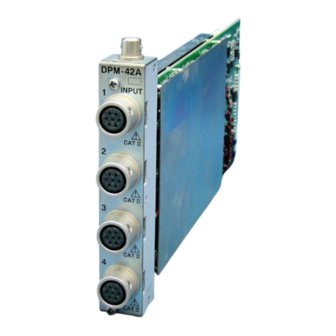
1-5 CONTROLS AND INDICATORS DPM-42A(-F) DPM-42A-1(F1) (Input connector: TAJIMI made) (Input connector: LEMO made) 1) Input connector 1 ......Input connector of the 1st channel. 2) Input connector 2 ......Input connector of the 2nd channel. 3) Input connector 3 ......Input connector of the 3rd channel. -
Page 11: Pin Assignment And Connection Of Connectors
1-6 PIN ASSIGNMENT AND CONNECTION OF CONNECTORS [Pin assignment] 1) Input Connector DPM-42A DPM-42A-1 Pin assignment of input connectors (TAJIMI made connector) (LEMO made connector) (Common to both connectors) Signal Name +Bridge excitation voltage -Input -Bridge excitation voltage +Input FG (GND) - Page 12 For how to connect the DPM card to a bridge box, see “Measurement Memo: How to Assemble a Bridge Gage Bridge” in KYOWA’s union catalog or bridge box instruction manual. When one end of the strain gage transducer is equipped with no plug, there are 2 ways for connecting the strain gage transducer to the DPM card.
- Page 13 (2) DPM-42A-1(F1) How to connect conductors to a plug for the DPM-42A-1(F1) is the same as the method for the DPM-42A(-F). If the plug used for the bridge box or strain gage transducer is PRC03-12A10-7M10 (TAJIMI made), use an optional input conversion cable [U-110].
-
Page 14: Installation Of Card
DPM-42A “Card Type,” it is required to update the EDX-2000A DPM-42A hardware. Contact KYOWA or our representative for updating the EDX-2000A hardware. NOTE When installing the DPM card in the EDX-2000A, do not touch any component parts of the card. Or,... -
Page 15: How To Set The Dpm Card
EDX-2000A Initial Screen <Oscillator Setting Order> EDX-2000A Initial Screen When the DPM card is correctly installed in the EDX-2000A, “DPM-42A” appears on the initial screen. (The following screen shows that ‘1’ DPM card is installed in the 1st slot.) Here, select the cursor to menu item 5) <Environment>... - Page 16 Environment Select item 5) <Environment> from the main menu of the initial screen to display the right screen. Here, select the cursor to item 9) <Oscillator> and press the ENTER key. Oscillator An “Oscillator” setting window appears as shown at the right. Select the cursor to the desired oscillator and press the ENTER key.
-
Page 17: Setting Ch
30 Hz 10 kμm/m 10 Hz 20 kμm/m AUTO* 50 kμm/m ↓ *Displayed only on the DPM-42A-F(F1). EDX-2000A Initial Screen (Note) Selectable range varies with Mode. ↓ 1) Measurement <Procedures for Setting CHs> EDX-2000A Initial Screen Here, select the cursor to item 2) Condition from... - Page 18 Condition Setting Screen Select item 2) <Condition> from the main menu on the initial screen to display the right screen. Here, select the cursor to item 1) <Channel Cond> from the <Condition> main menu and press the ENTER key. MEMO If no conditioner card is installed, CH column and items that are not available for setting are indicated with “*.”...
- Page 19 Range Select item 3) <Range> from the <Channel Cond> menu to display the right screen with “Range” setting window. Here, set an appropriate measuring range according to the measuring mode. BV(2.0)V: 200 μm/m, 500 μm/m, 1 kμm/m, 2 kμm/m, 5 kμm/m, 10 kμm/m, 20 kμm/m, and OFF BV(0.5)V: 1 kμm/m, 2 kμm/m, 5 kμm/m, 10 kμm/m, 20 kμm/m, 50 kμm/m, and OFF It is required to select an appropriate measuring range according to the magnitude of the input signal.
- Page 20 Sampling frequency range usable for the anti-alising filter is 100 Hz or more. Although the card type is DPM-42A-F, if “AUTO” is not displayed on the “Low Pass Filter” setting window, check whether or not the sampling frequency is set to less than 100 Hz.
- Page 21 BAL ON/OFF Select item 5) <BAL ON/OFF> from <Channel Cond> menu to display the right screen with “Balance ON/OFF” setting window. Here, select the cursor to “ON” or “OFF” and press the ENTER key. Only CHs that are set to “ON”...
- Page 22 NOTE When balance is conducted to the DPM card, not only initial balance is adjusted when sensors are connected or changed but also offset value is calculated when standard equivalent strain (CAL) is entered. When the following conditions are changed, re-conduct the balance once again. •...
- Page 23 • When SHUNT is selected Input fixed resistance between [+ Bridge excitation voltage] and [- Input] of the strain gage bridge and add a certain value to the current output and display the obtained value. The output value is determined by the bridge resistance of the strain gage bridge irrespective of the CAL range.
- Page 24 Measurement After all the settings are complete, select item 0) <End> from the <Channel Cond> menu to return to the EDX-2000A initial screen as shown in the right. Here, select item 1) <Measurement> from the main menu to start the measurement with the determined channel conditions.
-
Page 25: Setting Internal Sensitivity Compensation
2-3 SETTING INTERNAL SENSITIVITY COMPENSATION Internal sensitivity compensation is a function used in the following case. • When setting the oscillator to the “external oscillator.” • When compensating sensitivity • When the input cable is long • When connecting a sensor at the first stage When compensating the internal sensitivity, the sensitivity is finely adjusted by the internal CAL. - Page 26 Condition Setting Screen Select the item 2) <Condition> from the main menu to display the right screen. Here, select the cursor to item 5) <Comp IntSense> and press the ENTER key. Comp IntSense Select item 5) <Comp IntSense> from the <Condition>...
- Page 27 If there are CHs that are set to “ON” for “Comp Target,” the “Internal Sensitivity Compensation” screen appears as shown at the right and menu items 2) <Compensate> and 3) <Initialize> are added to the menu. Here, select the cursor to item 2) <Compensate> and press the ENTER key.
- Page 28 Sensitivity of CHs subjected to internal sensitivity compensation is compensated. To initialize the compensation, select the cursor to item 3) <Initialize> press the ENTER key. Initialize A “Initialize” setting window appears. Conduct Initialize → ENTER key Stop Initialize → ESC key After a while, it automatically ends Initialize operation and results of sensitivity compensation are shown on the “Comp Rsl”...
-
Page 29: Specitifications
Reading TEDS internal sensor information Input Connector ........NDIS connector (DPM-42A and DPM-42A-F) LEMO connector (DPM-42A-1 and DPM-42A-F1) Anti-alising Filter ........ [Applied only to DPM-42A-F and DPM-42A-F1] 8th butterworth type Cutoff frequency:Automatically set to [Sampling frequency × 0.25]. Cutoff characteristics:-48 dB ±5 dB (when sampling frequency × 0.5) Note) This setting is activated when low pass filter is set to [AUTO] in EDX-2000A. -
Page 30: Outside Drawing
3-2 OUTSIDE DRAWING <DPM-42A (TAJIMI made input connector)> <DPM-42A-1 (LEMO made input connector)>... - Page 31 <DPM-42A-F (TAJIMI made input connector)> <DPM-42A-F1 (LEMO made input connector)>...
-
Page 32: Optionals
4. OPTIONALS Input Conversion Cable (U-110) By connecting to a LEMO made input connector of the DPM-42A-1 (F1), this input conversion cable is capable of changing the input connector to TAJIMI made input connector. (Length: Approx. 50 cm) Monitor Output Cable (H-10296) By connecting to a monitor BNC connector, this monitor output cable is capable of monitoring data for every CH.
Need help?
Do you have a question about the DPM-42A and is the answer not in the manual?
Questions and answers