Table of Contents
Advertisement
Quick Links
LOW POWER STRAIN/VOLTAGE MEASURING UNIT
Generally, company names and trade names described in this Instruction Manual are trademarks or registered trademarks
of the companies.
This Instruction Manual may not be copied or reproduced, in whole or part, without consent of KYOWA.
Copyright © Kyowa Electronic Instruments Co., Ltd. All rights reserved.
The contents of the Instruction Manual are subjected to change without prior notice.
We assume no responsibility whatever for any damage resulting from the use of this product.
Thank you for purchasing KYOWA's product EDX-15A Low Power Strain/Voltage
Measuring Unit.
Read this Instruction Manual carefully in order to make full use of the high
performance capabilities of the product.
Do not use the product in methods other than described in this Manual.
This Manual only describes hardware operation of the EDX-15A. For the Dynamic
Data Recording Software DCS-100A, see the DCS-100A Instruction Manual (For
EDX-10A/B Operation).
INSTRUCTION MANUAL
Compact Recording System
IM-A-1072C February 2023
EDX-15A
Advertisement
Table of Contents

Related Manuals for KYOWA EDX-15A


Summary of Contents for KYOWA EDX-15A
- Page 1 Generally, company names and trade names described in this Instruction Manual are trademarks or registered trademarks of the companies. This Instruction Manual may not be copied or reproduced, in whole or part, without consent of KYOWA. Copyright © Kyowa Electronic Instruments Co., Ltd. All rights reserved.
-
Page 3: Table Of Contents
SAFETY PRECAUTIONS (Do not forget to read the safety precautions prior to use.) ...... 3 LIMITED LIFE PARTS AND PREVENTIVE MAINTENANCE ........6 EDX-15A REPLACEMENT BEFORE THE END OF SERVICE LIFE ........6 NOTATIONS USED IN THE INSTRUCTION MANUAL ..........6 IMPORTANT PRECAUTIONS WHEN USING EDX-15A .......... -
Page 4: Standard Accessories
STANDARD ACCESSORIES The following accessories are packed with the EDX-15A. When unpacking, check the contents to ensure that all accessories are enclosed. Input cable U-124: ・・・・・・・・・・・・・・・・・・・・・・・・・・・・・・・・・・・・・・・ Voltage conversion adapter FV-1A: ・・・・・・・・・・・・・・・・・・・・・・・・・・・ Rubber Foot: 8/sheet ・・・・・・・・・・・・・・・・・・・・・・・・・・・・・・・・・・・・・・・・・・・・ Screws (cross recessed head): ・・・・・・・・・・・・・・・・・・・・・・・・・・・・・・・... -
Page 5: Safety Precautions
HARDWARE)” and “EDX-15A Instruction Manual”. Avoid using in environment with inflammable gas, etc. To prevent the risk of fire hazard or explosion, do not use the EDX-15A in environment with inflammable gas, vapor, or dust. If any trouble occurs To prevent fire hazards, if smoke is emerging from the EDX-15A, immediately disconnect the USB cable or AC adapter to terminate the system operation. - Page 6 294m/s (30G)/11msec Use the EDX-15A in an area where vibration and impact can be kept within the scope of specifications. Continuous vibration or severe impact may cause deteriorated performance and system failure. Do not use the EDX-15A in strong electromagnetic field.
- Page 7 CAUTION Do not apply any voltage beyond the specified input voltage range. Failure to do so will pose the risk of deteriorated performance and system failure. See the following precautions before measuring. 1) Use a tester or the like to measure the voltage between negative sides of the DC voltage and confirm that the voltage is approximately 0 V.
-
Page 8: Limited Life Parts And Preventive Maintenance
EDX-15A. Regardless of the replacement parts, the EDX-15A itself gradually deteriorates with age. Before the expected service life is reached, consider replacing the EDX-15A with a new one or the latest series as preventive maintenance. NOTATIONS USED IN THE INSTRUCTION MANUAL... -
Page 9: Important Precautions When Using Edx-15A
2. After the power ON, always preheat the EDX-15A for approximately 10 minutes. CE MARKING NOTE 1. Be sure to use the input cable (U-124) for the EDX-15A. Wrap the ferrite core two turns around every channel cable. Recommended ferrite core Model: E04SR170730A Seiwa Electric Mfg. -
Page 10: Outline Of The Product
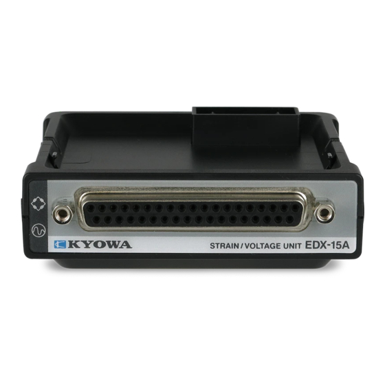
1. OUTLINE OF THE PRODUCT 1-1. OUTLINE OF THE PRODUCT The EDX-15A is a measuring unit for a strain gage transducer and voltage. The EDX-15A has to be installed in the EDX-10B. One EDX-15A is capable of measurement of 4 channels and maximum 16 channels with four EDX-15A units. -
Page 11: Controls And Indicators
Connect the accessory input cable (U-124) or optional accessory input adapter (UI-51A).etc. (2) Fixing metal For fixing the D-sub connector of the input cable (U-124). 2-2. TOP (3) Unit-coupling Connector for connecting the EDX-10B or measuring units on the EDX-15A. Connector... -
Page 12: Side
2-3. SIDE (4) Clearance hole For fixing the EDX-10B or measuring unit on the EDX-15A by using a screw. (5) Finger slot For connecting/disconnecting the EDX-10B and a measuring unit. (6) Rubber foot slot The EDX-15A has small rubber feet (optional) to keep it from sliding around when placed on a flat surface. -
Page 13: Pin Assignment And Connection Of Input Connector
3. PIN ASSIGNMENT AND CONNECTION OF INPUT CONNECTOR 3-1. PIN ASSIGNMENT OF INPUT CONNECTORS Pin No. Signal Name Function Pin No. Signal Name Function CH1 A CH1 +BV CH1 B CH1 -IN CH1 D CH1 +IN CH1 C CH1 -BV CH2 B CH2 -IN CH2 A... -
Page 14: Connect The Measuring Units
For detale, “EDX-10B Instruction Manual (FOR HARDWARE) 3-2-1.NUMBER OF CONNECTABLE MEASURING UNIT”. (If you use EDX-10A, the number of connectable measuring unit is one.) 1) To connect the EDX-10B or a measuring unit on the EDX-15A, remove the cap of the EDX-10B or a measuring unit to be connected. -
Page 15: Connect A Strain Gage Transducer
4. CONNECT A STRAIN GAGE TRANSDUCER The EDX-15A is a measuring instrument for a strain gage transducer. The input cable should be connected as follows. NOTE Before connecting a sensor, disconnect the USB cable and AC adapter from the EDX-10B to turn OFF the power. -
Page 16: When Using The Optional Accessory Input Adapter (Ui-51A)
MEMO Before recording data, select the strain mode and monitor the noise. If excessive noise is measured, ground the shield of the output cable or connect it to the GND terminal of the EDX-10B, whichever results in less noise. NOTE ■... -
Page 17: Connect Voltage
5. CONNECT VOLTAGE The EDX-15A is a measuring instrument for voltage. The input cable should be connected as follows. NOTE Before connecting voltage, disconnect the USB cable and AC adapter from the EDX-10B to turn OFF the power. 5-1.When using the standard accessory input cable (U-124) and voltage conversion adapter (FV-1A) 1) When measuring the voltage, connect the voltage conversion adapter (FV-1A) to the input cable (U-124) as lower figure. - Page 18 MEMO Before recording data, select the voltage mode and monitor the noise. If excessive noise is measured, ground the shield of the output cable or connect it to the GND terminal of the EDX-10B, whichever results in less noise. NOTE ■...
-
Page 19: When Using The Optional Accessory Input Cable (U-125)
5-2. When using the optional accessory input cable (U-125) 1) Connect the BNC connector to the D-sub connector of the input cable (U-125). 2) Insert the D-sub connector case into the input connector of the EDX-15A. 3) Fasten the D-sub connector case tightly with the two screws. -
Page 20: When Using The Accessory Input Adapter (Ui-51A)
5-3. When using the accessory input adapter (UI-51A) 1) When the cable, connected to the battery has bare wires, solder the bare wires onto the input adapter tab as follows. Maintain the temperature of the soldering iron tip between 260 to 350˚C (within 5 seconds). Input adapter tab Solder the bare wires. - Page 21 WARNING ■ Do not apply any voltage beyond the specified input voltage range. The input voltage range of the EDX-15A is ±50V. Failure to do so will pose the risk of electric shock, deteriorated performance and system failure. ■ Precautions when measuring the DC voltage of a battery, power supply, etc.
-
Page 22: Trouble Shooting
6. TROUBLE SHOOTING When the EDX-15A does not operate as expected or when it operates unstably, trace the cause before concluding a defect of EDX-15A. Items to be checked and countermeasure against various phenomena are described in the following table. -
Page 23: Maintenance
Must be returned to KYOWA for the scheduled maintenance inspection. measuring units Particularly if the EDX-15A is used continuously for long periods of time, early replacement of parts is required for the purposes of safety and stable operation. -
Page 24: Specifications
8. SPECIFICATIONS Item Strain measurement Voltage measurement Name Low power strain/voltage measuring unit Model EDX-15A Compatible sensor Strain gage transducer and strain gage (*1) Voltage (Unbalanced input) The number of input channels Measurement range 10000, 50000 µm/m (2 range) 10, 50V (2 range) Compatible bridge resistance 120 to 1 kΩ... -
Page 25: Outside Drawing
9. OUTSIDE DRAWING Unit: mm...
Need help?
Do you have a question about the EDX-15A and is the answer not in the manual?
Questions and answers