Table of Contents
Advertisement
Quick Links
Windows are trademarks of Microsoft Corporation, registered in the U.S.A. and other countries.
Generally, company names and trade names described in this Instruction Manual are trademarks or registered
trademarks of the companies.
This Instruction Manual may not be copied or reproduced, in whole or part, without consent of KYOWA.
Copyright © Kyowa Electronic Instruments Co., Ltd. All rights reserved.
The contents of the Instruction Manual and specifications of the software are subject to change without prior
notice.
Kyowa Electronic Instruments Co., Ltd. assumes no liability for any damage resulting from the use of the
software.
INSTRUCTION MANUAL
Thank you for purchasing KYOWA's product EMON-20A Monitor Unit.
Read this Instruction Manual carefully in order to make full use of the high
performance capabilities of the product.
Do not use the product in methods other than described in this Manual.
This Manual only describes operations of the EMON-20A.
For the Universal Recorder EDX-100A, refer to the "EDX-100A
INSTRUCTION MANUAL (FOR HARDWARE)."
For the Universal Recorder EDX-200A, refer to the "EDX-200A
INSTRUCTION MANUAL (FOR HARDWARE)."
For the Dynamic Data Recording Software DCS-100A, refer to the "DCS-
100A INSTRUCTION MANUAL (FOR EDX-100A OPERATION)" and
"DCS-100A INSTRUCTION MANUAL (FOR EDX-100A OPERATION)."
IM-A-1122 December 2016
EMON-20A
MONITOR UNIT
Advertisement
Table of Contents

Related Manuals for KYOWA EMON-20A


Summary of Contents for KYOWA EMON-20A
- Page 1 Generally, company names and trade names described in this Instruction Manual are trademarks or registered trademarks of the companies. This Instruction Manual may not be copied or reproduced, in whole or part, without consent of KYOWA. Copyright © Kyowa Electronic Instruments Co., Ltd. All rights reserved.
-
Page 2: Table Of Contents
3-8-6 “Set XY Scale” window ··································································· 28 3-8-7 “X/Y Axis Scale” window ································································· 29 3-8-8 “X/Y Axis Line” window ·································································· 30 4 INSTALLING AND CONNECTING THE EMON-20A ················································· 31 4-1 TO INSTALL THE EMON-20A ································································ 31 4-2 TO CONNECT THE DEDICATED CABLES ····················································· 32 4-3 TO CONNECT THE POWER SUPPLY ··························································... - Page 3 5-2 BEFORE MONITORING/RECORDING DATA ··················································· 44 5-3 TO OPERATE THE EMON-20A ······························································· 45 5-3-1 To operate the EMON-20A while it is stopped ················································· 45 5-3-2 To operate the EMON-20A while monitoring/recording data ······································ 47 5-4 TO DISPLSY THE [OVER] ICON ····························································· 48 6 MENU ·······················································································...
- Page 4 8-1-1 To select files ··········································································· 72 8-1-2 To set display conditions ·································································· 73 8-1-3 All Display ············································································· 74 8-2 TO DISPLAY THE CURSORS ································································ 76 8-2-1 To change the cursor mode ································································ 76 8-2-2 To change/move the cursors ································································ 76 8-2-3 Analyzed information ····································································...
-
Page 5: Standard Accessories
STANDARD ACCESSORIES The following accessories are packed with the EMON-20A. When unpacking, check the contents to ensure that all accessories are enclosed. Instruction manual 1 set (DVD-R) *1 Test certificate with warranty EMON-20A dedicated cable Read in the beginning *1 Including For the Dynamic Data Recording Software DCS-100A trial version and Instruction manual. -
Page 6: Safety Symbols
WARNING Warning Be sure to observe the warning and precautions described in the EMON-20A INSTRUCTION MANUAL. Power supply To prevent a fire hazard, ensure that the power supply voltage specified for the product matches the local line voltage before connecting the system to the DC power. - Page 7 CAUTION Precautions Be sure to observe the warning and precautions described in the “EMON-20A INSTRUCTION MANUAL.” Use the product with the temperature ranging from 0 to 50℃. Otherwise, it may lower the performance and other issues may occur.
- Page 8 CAUTION The AC adapter (UIA345-12) is a consumable item. Do not pull cords and cables. Lay cords and cables with a certain allowance so that excessive force is not applied to the connections. Pulling or applying excessive force may cause negatively affect or interrupt the measurement. ...
-
Page 9: Notations Used In The Instruction Manual
Essential precautions required when handling the product. MEMO Reference items required when handling the product. IMPORTANT PRECAUTIONS WHEN USING EMON-20A NOTE When the EDX-100A/200A version is lower than 2.00, you are not able to control the EDX-100A/200A by using the EMON-20A. -
Page 10: Outline Of Product
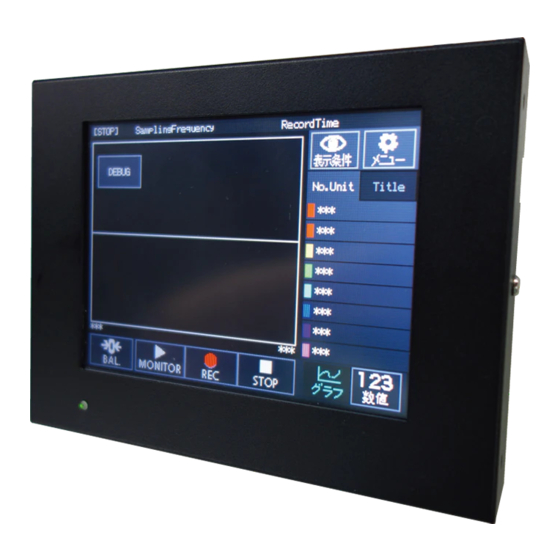
1-1 OUTLINE The EMON-20A is a simplified monitor unit for the EDX-100A/200A series. Since the EMON-20A has a touch panel, the EMON-20A monitors the measured data on sites where you are not able to use the PC. The EMON-20A sets the channel conditions and checks the measured data files also. -
Page 11: Operations And Functions
6-3-5 To set the LPF 6-3-6 To display the CH titles 6-4-1 To check the EDX information 6-4-2 To check the EDX version information 6-5 TO SET THE EMON-20A 6-5-1 Language 6-5-2 Background color of graph 6-5-3 Buzzer sound 6-5-4 Backlight... -
Page 12: List Of Window Configuration
2-2 LIST OF WINDOW CONFIGURATION Load the channel conditions and measuring conditions. * The Y-Time graph window appears for the first time. Windows Each key “Sampling Frequency” window [Return] button “Display Conditions” window “CH Condition Config” window [OK] button “EDX Information” window [Return] button [OK] button... -
Page 13: Controls And Indicators
3 CONTROLS AND INDICATORS 3-1 MEASURING WINDOWS 3-1-1 Y-Time graph (monitoring data) ① ② ③ ④ ⑤ ⑥ ⑦ ⑧ ⑨ ⑩ ⑪ ⑫ ⑬ ① Sampling Freq The pre-set sampling frequency appears. ② Rec Time The max. recording time at the pre-set sampling frequency appears. ③... -
Page 14: Numeric Window (Monitoring Data)
3-1-2 Numeric window (monitoring data) ① ② ③ ④ ⑤ ⑥ ⑦ ⑧ ⑨ ⑩ ⑪ ⑫ ⑬ ① Sampling Freq The pre-set sampling frequency appears. ② Rec Time The max. recording time at the pre-set sampling frequency appears. ③ Status The current status of the EDX-100A/200A appears as follows. -
Page 15: Y-Time Graph/Numeric Window (Stopped)
3-1-3 Y-Time graph/numeric window (stopped) ① ② ② ① ① [→CH] button Changes the channel list on the “Displayed CH Select” window (hereinafter referred to as the “pre-set channel list”) to the first 8 channels (CH001 to CH008). When the EDX-100A/200A has multiple conditioner cards and the first 8 channels (CH001 to CH008) appear on the window, click the [→CH] button to display the next 8 channels. -
Page 16: Menu" Window
3-2 “MENU” WINDOW ① ② ③ ④ ⑤ ⑥ ⑦ ① [Data Check] button The “Data Check” window appears. ② [CH/Measuring Condition Read] button Loads the channel conditions and measuring conditions from the connected EDX-100A/200A. ③ [Sampling Frequency] button The “Sampling Frequency” window appears. ②... -
Page 17: Sampling Frequency" Window
3-3 “SAMPLING FREQUENCY” WINDOW ① ② ③ ④ ⑤ ⑥ ⑦ ① Rec Time The max. recording time at the pre-set sampling frequency appears. ② [2^N Series] button 4 Hz to 65,536 Hz in 2^n series. As you click the button, the button is highlighted and a check mark is placed. ③... -
Page 18: Condition Set" Window
3-4 “CH CONDITION SET” WINDOW ① ② ③ ④ ⑤ ⑥ ⑦ ⑧ ⑨ ⑩ ① [Measure ON/OFF] button Sets the measure ON/OFF of every channel of the EDX-100A/200A. ② [Mode] button Sets the mode of every channel of the EDX-100A/200A. ③... -
Page 19: Edx Information" Window
3-5 “EDX INFORMATION” WINDOW 3-5-1 “EDX Information” window ① ② ③ ④ ⑤ ① EDX information The ID and model of the EDX-100A/200A appear. ② [←/→] button Changes the EDX-100A and EDX-200A during the synchronous operation. ③ Card information The slot Numbers and models of the cards, mounted in the EDX-100A/200A, appear. -
Page 20: Version Information" Window
3-5-2 “Version Information” window ① ② ③ ④ ① Connected measuring machine The number of the EDX-100A/200A units appears. ② [↑/↓] button When the number of EDX-100A/200A units is 3, click the [↓] button to display the information of the 3rd EDX-100A/200A. ③... -
Page 21: Emon Set" Window
Selects the required time to turn OFF the backlight without touching the touch panel. ⑤ [Network] button The “Network Set” window appears. ⑥ [Version] button The firmware versions, etc. of the EMON-20A appear. ⑦ [Update] button Becomes the “update standby” mode. For details, see “UPDATING THE EMON-20A” provided separately. ⑧ [Initialize] button Initializes the EMON-20A settings to the initial values. -
Page 22: Network Set" Window
The subnet mask of the EMON-20A appears. As you click the button, the “Subnet Mask” window appears. ③ [Initialize Network] button Initializes the EMON-20A IP address and subnet mask to the initial values. ④ [Return] button Returns to the “EMON Set” window. -
Page 23: Ip Address" Window
Note that the number of each block is within 3 digits. Clears all block values to “0”. ⑤ [All Clear] button ⑥ [OK] button Saves the network status in EMON-20A. The “Network Set” window appears. ④ [Cancel] button Returns to the “Network Set” window. -
Page 24: Data Check" Window
3-7 “DATA CHECK” WINDOW 3-7-1 “Data check” window (Y-Time graph) ① ② ③ ④ ⑤ ⑥ ⑦ ⑧ ⑨ The “Select File” window appears. ① [Folder] button Selects the files for displaying on the Y-Time graph. The “Display Conditions” window appears. ②... -
Page 25: Select File" Window
3-7-2 “Select File” window ① ② ③ ④ ⑤ ⑥ ① File button As you click the button, the button is highlighted and a check mark is placed. The latest files appear from No. 01. ② [↑/↓] button [↓] button: The No.5 to No.10 files appear. -
Page 26: File Details" Window
3-7-3 “File details” window ① ② ③ ④ ⑤ ⑥ ① File No./Name The file No. and name, selected on the “Select File” window, appears. When the filename is too long to display, 6 characters (including the first 5 characters and last 1 character of the filename) appear. -
Page 27: Display Conditions" Window
3-8 “DISPLAY CONDITIONS” WINDOW 3-8-1 “Display Conditions” window ① ② ③ ④ The “Displayed CH Select” window appears. ① [Select Displayed CH] button The “Set XY Scale” window appears. ② [XY-axis Config] button ③ [All Display] button Displays all data of the file on the single window. To use this function, make sure the files are opening on the “Data check”... -
Page 28: Displayed Ch Select" Window
3-8-2 “Displayed CH Select” window ① ② ③ ④ ⑤ ① [ON/OFF] button Selects the show (ON)/hide (OFF) of the assigned display channel on the measuring window or “Data check” window. ② [Displayed CH assign] button Assigns a channel to be displayed on the measuring window or “Data check” window. The assigned CH No. -
Page 29: Assigned Ch Select" Window
3-8-3 “Assigned CH Select” window ① ② ③ ④ ⑤ ⑥ ⑦ ⑧ ⑨ ⑩ ① Current channel color The channel color of the target ⑤[Select Displayed CH] button the“Displayed CH Select” window appears. ② EDX information The model and ID of the current EDX-100A/200A and mounting conditioner card information appear. -
Page 30: Can-Ch Select" Window
3-8-4 “CAN-CH Select” window ① ② ③ ④ ⑤ ⑥ ⑦ ① [CAN-ID] button Sets the CAN-ID. ② [CAN-CH] button Sets the CAN-CH No. ③ Numeric keypad Enters the CAN-ID or CAN-CH No. [BS] key: Clears the number in the target block from the rightmost digit. [C] key: Clears the target block value to “0.”... -
Page 31: Can Detail" Window
3-8-5 “CAN Detail” window ① ② ③ ④ ① CAN-CH Information The current EDX-ID, CAN-ID, and CAN-CH No. appear. ② [↑/↓] button Changes the CAN-CH information and CAN communication conditions. ③ CAN Comm The current port No., Can Comm Std, Comm Speed, and Term Resis appear. Returns to the “CAN-CH Select”... -
Page 32: Set Xy Scale" Window
3-8-6 “Set XY Scale” window ① ③ ② ④ ⑤ ⑥ ⑦ ⑧ ① [Set X Area Scale, start point] button Sets the start point of the x-axis on the Y-Time graph window. ② [Set Y Area Scale, start point] button Sets the start point of the y-axis on the Y-Time graph window. -
Page 33: X/Y Axis Scale" Window
3-8-7 “X/Y Axis Scale” window ① ② ③ ④ ⑤ ① [Start point] button Enters the start point by using the ③ numeric keypad. ② [Endpoint] button Enters the endpoint by using the ③ numeric keypad. ③ Numeric keypad Enters the start point and endpoint. [BS] key: Clears the number in the target block from the rightmost digit. -
Page 34: X/Y Axis Line" Window
3-8-8 “X/Y Axis Line” window ① ② ③ ① Division line button As you click the button, the button is highlighted and a check mark is placed. ② [↑/↓] button Changes the division line buttons. ③ [OK] button Saves the division line settings. The “Set XY Scale”... -
Page 35: Installing And Connecting The Emon-20A
Mount the conditioner cards in the EDX-100A/200A in advance. 4-2 To connect dedicated cables Connect the EDX-100A/200A by using the EMON-20A dedicated cables. ↓ 4-3 To connect the power supply Connect the DC power supply or AC adapter and ground it. -
Page 36: To Connect The Dedicated Cables
Connect the D-sub connector (15 pins) of the dedicated cable to the [INPUT] connector, located on the back panel of the EMON-20A. Connect the metal connector (4 pins) of the dedicated cable to the DC power supply or AC adapter. -
Page 37: To Connect The Power Supply
Use the external power supply which has the larger current than the current consumption. Be sure to connect the GND terminal, located on the right side of the EMON-20A, to the ground. Otherwise, it may cause an electric shock hazard, lower the performance, and cause trouble. - Page 38 Metal connector (4 pins) of the dedicated cable Be sure to connect the GND terminal, located on the right side of the Optional accessory DC power cable EMON-20A, to the ground. Black, Green Red, White DC Power Supply Connect the metal connector (4 pins) of the P-76 and metal connector (4 pins) of the dedicated cable.
-
Page 39: To Connect The Ac Adapter
AC power outlet. Otherwise, it may cause system failures and accidents. Be sure to connect the GND terminal, located on the right side of the EMON-20A, to the ground. Otherwise, it may cause an electric shock hazard, lower the performance, and cause trouble. -
Page 40: To Connect The Interfaces
4-4 TO CONNECT THE INTERFACES This section describes how to connect the interfaces of the EMON-20A and that of the EDX-100A/200A. For details during the synchronous operation, see “EDX-100A INSTRUCTION MANUAL (FOR HARDWARE)” and “EDX-200A INSTRUCTION MANUAL (FOR HARDWARE).” NOTE When the EMON-20A is controlling the EDX-100A/200A, you are not able to control the EDX- 100A/200A by using the PC. -
Page 41: To Connect The Units During Synchronous Operation
USB/LAN switch = LAN Dedicated cable xample of the Master EDX-100A IP address settings: 192.168.200.100 LAN hub To [CONT IN] xample of the EMON-20A LAN straight cable IP address settings: 192.168.200.220 Slave EDX ID switch = 1 USB/LAN switch = LAN... - Page 42 You are not able to execute the synchronous operation when connecting the LAN hub between the EDX-200A units. Do not connect the units by using the wireless LAN function. MEMO You are able to connect the LAN hub - 100Base-TX or higher - between the EMON-20A and EDX-200A.
-
Page 43: To Connect The Edx-100A Units And Edx-200A Units During Synchronous Operation
EDX-100A as second slave unit. 4-4-4 To extend the LAN cable The length of the LAN cable between the EMON-20A and EDX-100A/200A is max. 100 m. To extend the LAN cable, connect the LAN connector of the dedicated cable to the LAN relay connector. -
Page 44: Lan Interface And Network Settings
Suppose the IP address of the EDX-100A/200A is [192.168.111.XXX]. Make sure the front part [192.168.111.] of the IP address of the EMON-20A is the same as the EDX- 100A/200A and rear part [XXX] of the IP address is not the same as the EDX-100A/200A. -
Page 45: Edx-100A/200A And Network Settings
Suppose the IP address of the EDX-100A/200A for the synchronous operation is [192.168.111.XXX]. Make sure the front part [192.168.111.] of the IP address of the EMON-20A is the same as the EDX- 100A/200A and rear part [XXX] of the IP address is not the same as the EDX-100A/200A. - Page 46 NOTE When the network settings failed, the EDX-100A/200 keep emitting the sound “pii, pii, ..” Check the condition setting files saved in the CF card. The factory-configured network settings of the EDX-100A are as follows. IP address: 192.168.100.100 Subnet mask: 255.255.255.
-
Page 47: To Fix The Emon-20A
4-6 TO FIX THE EMON-20A This section describes how to fix the EMON-20A by using the utility nuts located on the bottom panel, back panel, top panel, left panel, and right panel. The dimensions of utility nuts are as follows. -
Page 48: Monitoring/Recording Operations
The EMON-20A monitors the EDX-100A/200A, starts/stops recording data, and executes balance adjustments. ■Y-Time graphs and numeric windows The EMON-20A checks the measured data, assigned on the display channel, on the Y-Time graph or numeric window. The EMON-20A also checks whether the display channels exceed the measuring range while monitoring/recording data. -
Page 49: To Operate The Emon-20A
5-3 TO OPERATE THE EMON-20A 5-3-1 To operate the EMON-20A while it is stopped ■To open the “Menu” window. Click the [Menu] button. The “Menu” window appears. ■To open the “Display Conditions” window. Click the [DISP] button. The “Display Conditions” window appears. - Page 50 ■To feed/return the channel list. This section describes the operations by using the examples as follows. Example) Measuring window: Numeric window The “pre-set channel list”: CH001, 002, 004, 005, 006, 007, and 008(The CH003 is not the display channel.) The number of channels of the EDX-100A/200A during the synchronous operation: 64 channels 1) When the “pre-set channel list”...
-
Page 51: To Operate The Emon-20A While Monitoring/Recording Data
5-3-2 To operate the EMON-20A while monitoring/recording data ■To execute the balance adjustment. This section describes how to execute the balance adjustment of cards mounted in the EDX-100A/200A by pressing the [BAL.] button. 1) Click the [BAL.] button. The “Balance” pop-up window appears. -
Page 52: To Displsy The [Over] Icon
To remove the [OVER] icons, check the assigned display channels do not exceed the measuring range and start monitoring/recording data. When the measured data exceeds the measuring range and with the [Buzzer Sound] button OFF on the “EMON Config” window, the EMON-20A does not emit buzzer. -
Page 53: Menu
1) Click the [Menu] button. 2) Click the [CH/Measuring Condition Read] button. 3) Click the [Load] button. 4) After the EMON-20A loads the channel conditions and measuring conditions correctly from the EDX-100A/200A, the left message appears. Click the [Close] button. -
Page 54: To Set The Sampling Frequency
6-2 TO SET THE SAMPLING FREQUENCY Example) This section describes how to change the sampling frequency from “10k Hz” to “20k Hz.” 1) Click the [Sampling Frequency] button. 2) The [10k Hz] button is highlighted, and a check mark is placed. 3) Click the [20k Hz] button. -
Page 55: To Set Channel Conditions
You are not able to set the channel conditions (excluding the measure ON/OFF, mode, range, and LPF) from the EMON-20A. You are not able to set the CAN conditions from the EMON-20A. To set the channel conditions other than those described in the above, use the DCS-100A, etc. -
Page 56: To Set The Mode
The items are saved. To cancel, click the [Return] button. MEMO As you update the mode, the EMON-20A updates the range (10.0 V in this example) also. 6-3-4 To set the range Example) This section describes how to change the CH001 range from “100kue” to “20kue.”... -
Page 57: To Set The Lpf
6-3-5 To set the LPF Example) This section describes how to change the CH001 LPF from “100Hz” to “300Hz.” 1) Click the [100Hz] button of the CH001. 2) The [100kue] button is highlighted, and a check mark is placed. Click the [300Hz] button. The button is highlighted, and a check mark is placed. -
Page 58: To Check The Edx Information
6-4 TO CHECK THE EDX INFORMATION This section describes how to check the number of units and ID Numbers of the EDX-100A/200A, connected to the EMON-20A, and mounted conditioner cards and firmware version. 6-4-1 To check the EDX information This section describes how to display the ID Numbers, of the EDX-100A/200A and conditioner card models mounted on each slot. -
Page 59: To Check The Edx Version Information
This section describes how to check the EDX-100A/200A information and firmware versions and IP addresses of the EDX-100A/200A. 1) Click the [Version Information] button. 2) The following information appears. The number of EDX-100A/200A units connected to the EMON-20A, ID Numbers, models, firmware versions, and IP addresses of the EDX- 100A/200A Click the [Close] button. -
Page 60: To Set The Emon-20A
6-5 TO SET THE EMON-20A This section describes how to set the configuration of the EMON-20A. 6-5-1 Language This section describes how to select the EMON-20A language. 1) Click the [English] button. 2) The [English] button is highlighted, and a check mark is placed. -
Page 61: Buzzer Sound
6-5-3 Buzzer sound This section describes how to emit buzzer sound (ON)/not to emit buzzer sound (OFF) while operating the buttons on the EMON-20A. 1) The [Buzzer Sound] button “ON” is highlighted, and a check mark is placed. 2) Click the [Buzzer Sound] button “OFF”. -
Page 62: To Set/Initialize The Network Settings
6-5-5 To set/initialize the network settings This section describes how to set the IP address and subnet mask of the EMON-20A. ■To set network settings. Example) This section describes how to change the IP address from “192.168.100.220” to “192.168.200.220”. 1) Click the [Network] button “Setting”. - Page 63 NOTE After setting the network settings of the EMON-20A, be sure to turn OFF the power and turn ON again. Otherwise, the LAN communication may not work properly. MEMO To check the network settings, open the “Version Information” window. For details, see "6-5-7 To check the version."...
- Page 64 4) The last “Initialize network” window appears. To initialize network status, click the [Initial] button. To cancel, click the [Cancel] button. MEMO The factory-configured network settings of the EMON-20A are as follows. IP address: 192.168.200.220 Subnet mask: 255.255.255. 0 ...
-
Page 65: To Initialize
6-5-6 To initialize This section describes how to initialize the EMON-20A settings. 1) Click the [Initial] button. 2) The first “Initialize” window appears. To initialize, click the [Initial] button. To cancel, click the [Cancel] button. 3) The last “Initialize” window appears. -
Page 66: To Check The Version
6-5-7 To check the version This section describes how to check the firmware version, network settings, and serial No. of the EMON-20A. 1) Click the [Version] button. 2) The firmware version, network settings, and serial No. of the EMON-20A appear. -
Page 67: Display Conditions Settings
7 DISPLAY CONDITIONS SETTINGS 7-1 TO SELECT THE DISPLAY CHANNEL This section describes how to select the display channels of the EDX-100A/200A on the measuring window or “Data check” window. NOTE The display conditions on the measuring window are not the same as that of the “Data check” window. - Page 68 ■To change the EDX-100A/200A and conditioner cards This section describes how to change the master EDX-100A/200A, slave EDX-100A/200A, and conditioner cards during the synchronous operation only. 1) Click the [←/→] button located on the top right of the window. The master EDX-100A/200A or slave EDX-100A/200A appears on the upper side of the window.
-
Page 69: To Check The Ch Titles
■To show/hide display the display channels This section describes how to show (ON)/hide (OFF) the assigned display channels on the measuring window or “Data check” window. Example) This section describes how not to display the red CH001 on the measuring window or “Data check” window. -
Page 70: To Set Can-Chs
(channels which measure the data frames on CAN) as the display channels of the EMON-20A. ■To check the conditions on the DCS-100A To assign the “Measuring CAN-CH” as the display channel on the EMON-20A, set the CAN-ID No. and CAN- CH No. of the DCS-100A on the “Assigned CH Select” window. - Page 71 ■To assign the “Measuring CAN-CH” as the display channel Example) This section describes how to assign “Measuring CAN-CH” (EDX-ID: 0, CAN-ID: 1, CAN-CH: 1) to the yellow display channel. 1) Click the yellow [CH003] button. 2) Click the [CAN] button. MEMO The [CAN] button appears only when the EDX-100A/200A has the CAN-40A/41A.
- Page 72 MEMO The setting range of the CAN-IDs and CAN-CH Numbers are as follows. CAN-40A CAN-ID No.: 1 to 16, CAN-CH No.: 1 to 8 CAN-41A CAN-ID No.: 1 to 32, CAN-CH No.: 1 to 8 When you enter a value exceeding the range, the value automatically changes to the maximum value of each item.
-
Page 73: To Set The X/Y-Axis
7-2 TO SET THE X/Y-AXIS 7-2-1 X/Y-axis scale This section describes how to set the scale of the x/y-axis on the Y-Time graph. The setting methods of the x-axis are the same as the y-axis. ■Setting methods Example) This section describes how to set the x-axis scale “1 sec to 12 sec” on the Y-Time graph. 1) Click the [Set X Area Scale, start point] button “0s”or [Set X Area Scale, endpoint] button “10s”. - Page 74 ■ X-axis scale and the setting ranges The setting ranges of the x-axis scale on the measuring window/“Data check” window are as follows. The setting ranges of the x-axis scale on the measuring window X-axis start point: 0 s fixed X-axis endpoint: 1 s to 10 s (in units of 1 s) X-axis scale on the “Data check”...
-
Page 75: To Set The X/Y-Axis Division Lines
7-2-2 To set the x/y-axis division lines This section describes how to divide the x/y-axis displaying range by selecting the number of division lines of the Y-Time graph on the measuring window or “Data check” window. The setting methods of the x-axis are the same as the y-axis. Example) This section describes how to divide the y-axis displaying range on the “Data check”... -
Page 76: Data Checking
8 DATA CHECKING 8-1 TO CHECK DATA ON THE Y-TIME GRAPH This section describes how to select the single file, recorded in the CF card on the EDX-100A/200A, and display the data on the Y-Time graph. This section also describes how to check the display channels, which exceeds the measuring range, at the all display, 8-1-1 To select files Example) This section describes how to select the file (TEST011.KS2). -
Page 77: To Set Display Conditions
8-1-2 To set display conditions Set the display conditions (display channel selections and x/y-axis settings) of the Y-Time graph for checking data. NOTE The display conditions on the measuring window are not the same as that of the “Data check” window. To set the display conditions on the measuring window, click the [DISP] button on the measuring window for settings. -
Page 78: All Display
8-1-3 All Display This section describes how to load all measured channel data of the total recording time from the files and displays the assigned display channels (total 8 channels) on a single window of the Y-Time graph. When the display channel exceeds the range, the [OVER] icon appears next to the target channel on the [No.Unit/Title] tab. - Page 79 NOTE After the all display, the settings of the x/y-axis scale changes to the above scale values. Before the all display, set the above total recording time (round up at the once place) as the x-axis endpoint of the x-axis scale When the display channel exceeds the range, the [OVER] icon appears next to the target channel on the [No.Unit/Title] tab.
-
Page 80: To Display The Cursors
8-2 TO DISPLAY THE CURSORS This section describes how to display vertical/horizontal cursors on the Y-Time graph. [VRT] mode: The difference (sec) between the cursors on the x-axis and frequency (Hz) appear. [HRZ] mode: The difference between the cursors on the y-axis appears. 8-2-1 To change the cursor mode 1) Click the [VRT] button. -
Page 81: Analyzed Information
8-2-3 Analyzed information 1) [VRT] mode: The difference (sec) between the cursors on the x-axis and frequency (Hz) appear. Example) Right cursor: 4.010 Left cursor: 3.020 The difference between the cursors on the x-axis is as follows. dx: 4.010 - 3.020 = 0.990 s Frequency 1/dx: 1/0.990 = 1.010 Hz 2) [HRZ] mode: The difference between the cursors on the y-axis appears. -
Page 82: To Display/Delete Information Of Files
8-3 TO DISPLAY/DELETE INFORMATION OF FILES This section describes how to display the detailed information of the files and how to delete the files. 8-3-1 To display the detailed information of files Example) This section describes how to display the detailed information of the file (05 TEST011.KS2). 1) Click the [05 TEST011.KS2] button. -
Page 83: Precautions For Use
9 PRECAUTIONS FOR USE This section describes the informational notes when using the EMON-20A. For details of the EDX-100A/200A, see “EDX-100A INSTRUCTION MANUAL (FOR HARDWARE)” and “EDX- 200A INSTRUCTION MANUAL (FOR HARDWARE).” 9-1 PRECAUTIONS FOR EDX-200A SERIES 9-1-1 Limitations for dual sampling... -
Page 84: Precautions For Synchronous Operation
9-2 PRECAUTIONS FOR SYNCHRONOUS OPERATION 9-2-1 Precautions for display channels The selecting conditions of the display channels vary as follows. ■Y-Time graph *Unable to select multiple channels of multiple EDX units during the synchronous operation. *Able to select multiple channels of single EDX unit during the synchronous operation. ■Numeric window *Able to select multiple channels of multiple EDX units during the synchronous operation. -
Page 85: Limitations For The Number Of Edx-100A/200A Units
When the file capacity of the CF card is large and the number of files saved in the CF card is large, the EMON-20A takes time to display the files on the “Select File” window and takes time to draw the waveforms on the Y-Time graph. -
Page 86: Trouble Shooting
If the product is damaged due to any causes other than as written in the Instruction Manual or if the user has disassembled or remodeled the product, Kyowa Electronic Instruments Co., Ltd. may not be able to offer repair service. - Page 87 Take the following measures to protect against induction noise. Separately locate the product from the power source. Put the EMON-20A dedicated cables inside metal pipes to decrease effects due to the external noise. Be sure to connect the metal pipes, etc. to the ground. ...
-
Page 88: Error Messages
10-2 ERROR MESSAGES Error messages Checked items and countermeasures The EMON-20A is failure. Stop using the product. Hardware error occurred in ⇒ Contact Kyowa or our representatives. EMON-20A. Memory error occurred in EMON-20A. An error occurred while Make sure the LAN connector of the dedicated cable is connected to the communicating with EDX. -
Page 89: Maintenance
5 years. years Stuck pixels or dead pixels will appear, and LCD panel will fade. The product must be returned to Kyowa for replacements. AC adapter Service life, depends on the frequency of use and ambient Once in every 5 temperature, is approximately 5 years. -
Page 90: Specifications
(BAL) Channel conditions: Measure ON/OFF, measuring range, mode, and LPF Measuring conditions: Sampling frequency (7) Other functions EMON-20A settings Languages selection (English/Japanese), background color (black/white), operating beep (ON/OFF), backlight (lighting time), network settings, setting value initialization EDX Information... - Page 91 (11) Dimensions 166 mm (W) × 29 mm (H) × 128.5 mm (D) (excluding protrusions) (12) Weight Approx.550 g (13) Vibration resistance 29.4 m/s (3G), 5 to 200 Hz (14) Impact resistance 147.0 m/s (15G), 11 msec or less (15) Operating temperature range 0 to 50℃, 20 to 80 %RH (noncondensing) (16) Applicable conditioner cards for data acquisition Strain/Voltage/Acceleration Measurement Card CVM-40A, CVM-41A...
-
Page 92: Outside Drawing
12-2 OUTSIDE DRAWING...
Need help?
Do you have a question about the EMON-20A and is the answer not in the manual?
Questions and answers