Table of Contents
Advertisement
Quick Links
Generally, company names and trade names described in this Instruction Manual are trademarks or registered
trademarks of the companies.
This Instruction Manual may not be copied or reproduced, in whole or part, without consent of KYOWA.
Copyright © Kyowa Electronic Instruments Co., Ltd. All rights reserved.
The contents of the Instruction Manual are subjected to change without prior notice.
VOLTAGE MEASURING UNIT
Thank you for purchasing KYOWA's product EDX-12 Voltage Measuring
Unit.
Read this Instruction Manual carefully in order to make full use of the high
performance capabilities of the product.
Do not use the product in methods other than described in this Manual.
This Manual only describes hardware operation of the EDX-12A. For the
Dynamic Data Recording Software DCS-100A, see the DCS-100A Instruction
Manual (For EDX-10A Operation).
INSTRUCTION MANUAL
Compact Recording System
IM-A-938D February 2023
EDX-12A
Advertisement
Table of Contents

Subscribe to Our Youtube Channel
Related Manuals for KYOWA EDX-12A


Summary of Contents for KYOWA EDX-12A
- Page 1 Generally, company names and trade names described in this Instruction Manual are trademarks or registered trademarks of the companies. This Instruction Manual may not be copied or reproduced, in whole or part, without consent of KYOWA. Copyright © Kyowa Electronic Instruments Co., Ltd. All rights reserved.
-
Page 3: Table Of Contents
SAFETY PRECAUTIONS (Do not forget to read the safety precautions prior to use.) ..........3 LIMITED LIFE PARTS AND PREVENTIVE MAINTENANCE ................. 6 EDX-12A REPLACEMENT BEFORE THE END OF SERVICE LIFE ................ 6 NOTATIONS USED IN THE INSTRUCTION MANUAL .................... 6 IMPORTANT PRECAUTIONS WHEN USING EDX-12A ................... -
Page 4: Optional Accessories
STANDARD ACCESSORIES The following accessories are packed with the EDX-12A. When unpacking, check the contents to ensure that all accessories are enclosed. Input Adapter UI-51A: ・・・・・・・・・・・・・・・・・・・・・・・・・・・・・・・・・・・ Rubber Foot: 8/sheet ・・・・・・・・・・・・・・・・・・・・・・・・・・・・・・・・・・・・・・・・・・・ Screws (cross recessed head): ・・・・・・・・・・・・・・・・・・・・・・・・・・・・・・・ Term and Conditions of ・・・・・・・・・・・・・・・・・・・・・・・・・・・・・・... -
Page 5: Safety Precautions
HARDWARE) and EDX-12A Instruction Manual. Avoid using in environment with inflammable gas, etc. To prevent the risk of fire hazard or explosion, do not use the EDX-12A in environment with inflammable gas, vapor, or dust. If any trouble occurs To prevent fire hazards, if smoke is emerging from the EDX-12A, immediately disconnect the USB cable or AC adapter to terminate the system operation. - Page 6 Lay cords and cables with a certain allowance so that unreasonable force is applied to the connections. Failure to do so will pose the risk of erroneous data, disconnection and connector failure. Avoid installing sensors and EDX-12A near a welding machine. Failure to do so will pose the risk of erroneous data, malfunction and failure.
- Page 7 CAUTION Do not apply any voltage beyond the specified input voltage range (-50V to +50V). Failure to do so will pose the risk of deteriorated performance and system failure. See the following precautions before measuring. 1) Use a tester or the like to measure the voltage between negative sides of the DC voltage and confirm that the voltage is approximately 0 V.
-
Page 8: Limited Life Parts And Preventive Maintenance
EDX-12A. Regardless of the replacement parts, the EDX-12A itself gradually deteriorates with age. Before the expected service life is reached, consider replacing the EDX-12A with a new one or the latest series as preventive maintenance. -
Page 9: Important Precautions When Using Edx-12A
2. After the power ON, always preheat the EDX-12A for approximately 10 minutes. CE MARKING NOTE 1. Be sure to use the input cable for the EDX-12A. Wrap the ferrite core two turns around every channel cable. Recommended ferrite core Model: E04SR170730A Seiwa Electric Mfg. -
Page 10: Outline Of The Product
1. OUTLINE OF THE PRODUCT 1-1. OUTLINE OF THE PRODUCT The EDX-12A is a measuring unit for voltage. The EDX-12A has to be installed in the EDX-10A. One EDX-12A is capable of measurement of 4 channels and maximum 16 channels with 4 EDX-12A units. -
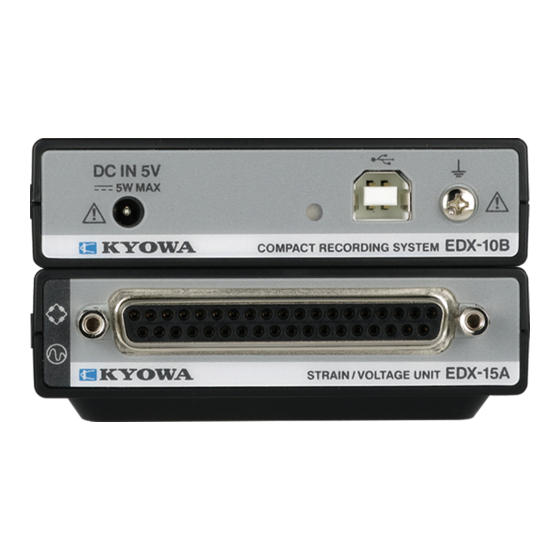
Page 11: Controls And Indicators
Connect the accessory input adapter (UI-51A) or optional accessory input cable (U-125). (2) Fixing metal For fixing the D-sub connector of the input cable (U-125). 2-2. TOP (3) Unit-coupling Connector for connecting the EDX-10A or measuring units on the EDX-12A. Connector... -
Page 12: Side
2-3. SIDE (4) Clearance hole For fixing the EDX-10A or measuring unit on the EDX-12A by using a screw. (5) Finger slot For connecting/disconnecting the EDX-10A and a measuring unit. (6) Rubber foot slot The EDX-12A has small rubber feet (optional) to keep it from sliding around when placed on a flat surface. -
Page 13: Pin Assignment And Connection Of Input Connector
3. PIN ASSIGNMENT AND CONNECTION OF INPUT CONNECTOR 3-1. PIN ASSIGNMENT OF INPUT CONNECTORS Pin No. Signal Name Function Pin No. Signal Name Function CH1 B CH1 -IN CH1 D CH1 +IN CH2 B CH2 -IN CH2 D CH2 +IN CH3 B CH3 -IN CH3 D... -
Page 14: Connect The Measuring Units
■ You can connect the measuring units up to 4 units. Do not connect 5 or more measuring units. 1) To connect the EDX-10A or a measuring unit on the EDX-12A, remove the cap of the EDX-10A or a measuring unit to be connected. -
Page 15: Connect Voltage
4. CONNECT VOLTAGE The EDX-12A is a measuring instrument for voltage. The input cable should be connected as follows. NOTE Before connecting voltage, disconnect the USB cable and AC adapter from the EDX-10A to turn OFF the power. 4-1. When using the accessory input adapter (UI-51A) 1) When the cable, connected to the battery has bare wires, solder the bare wires onto the input adapter tab as follows. - Page 16 WARNING ■ Do not apply any voltage beyond the specified input voltage range. The input voltage range of the EDX-12A is ±50V. Failure to do so will pose the risk of electric shock, deteriorated performance and system failure. ■ Precautions when measuring the DC voltage of a battery, power supply, etc.
-
Page 17: When Using The Optional Accessory Input Cable (U-125)
4-2. When using the optional accessory input cable (U-125) 1) Connect the BNC connector to the D-sub connector of the input cable (U-125). 2) Insert the D-sub connector case into the input connector of the EDX-12A. 3) Fasten the D-sub connector case tightly with the two screws. -
Page 18: Trouble Shooting
5. TROUBLE SHOOTING When the EDX-12A does not operate as expected or when it operates unstably, trace the cause before concluding a defect of EDX-12A. Items to be checked and countermeasure against various phenomena are described in the following table. -
Page 19: Maintenance
The EDX-12A is not designed for continuous operation of 24 hours. We do not guarantee the continuous operation of the EDX-12A and shall not be responsible for any failure of the EDX-12A to perform within the warranty period. -
Page 20: Specifications
7. SPECIFICATIONS (1) Compatible sensor Voltage (2) The number of input channels 4 (single-ended) (3) Measuring range 10 V or 50 V (4) Range accuracy Within ±0.3%FS (5)Balance adjustment range Within ±1/2 F.S. of setting range (6) Nonlinearity Within ±0.1%FS (7) A/D resolution 24 bits (8) Frequency response range... -
Page 21: Outside Drawing
8. OUTSIDE DRAWING Unit: mm...
Need help?
Do you have a question about the EDX-12A and is the answer not in the manual?
Questions and answers