
Related Manuals for Beckhoff EP5 Series


Summary of Contents for Beckhoff EP5 Series
- Page 1 Documentation EP5xxx EtherCAT Box Modules for Angle and Position Measurement Version: 2.3.0 Date: 2018-12-10...
-
Page 3: Table Of Contents
Table of contents Table of contents 1 Foreword .............................. 7 Notes on the documentation...................... 7 Safety instructions .......................... 8 Documentation issue status ...................... 9 2 Product overview............................. 11 EtherCAT Box - Introduction...................... 11 Module overview EP5xxx ........................ 13 EP5001-0002........................... 14 2.3.1 EP5001-0002 - Introduction..................... 14 2.3.2 EP5001-0002 - Technical data .................. 15 2.3.3 EP5001-0002 - Process image.................. - Page 4 Table of contents 4 Commissioning/Configuration ....................... 47 TwinCAT configuration setup, manual..................... 47 Configuration setup: TwinCAT - online scan ................... 50 Configuration via TwinCAT ...................... 57 EtherCAT slave process data settings (PDO) ................. 65 EP5001-0002 - Parameters and modes .................. 66 4.5.1 Process data........................ 66 4.5.2 DC (Distributed Clocks) .................... 68 4.5.3 Features CoE........................
- Page 5 Table of contents 5 Appendix .............................. 150 General operating conditions...................... 150 EtherCAT Box- / EtherCAT P Box - Accessories ................ 151 Support and Service ........................ 152 EP5xxx Version: 2.3.0...
- Page 6 Table of contents Version: 2.3.0 EP5xxx...
-
Page 7: Foreword
The TwinCAT Technology is covered, including but not limited to the following patent applications and patents: EP0851348, US6167425 with corresponding applications or registrations in various other countries. ® EtherCAT is registered trademark and patented technology, licensed by Beckhoff Automation GmbH, Germany. Copyright © Beckhoff Automation GmbH & Co. KG, Germany. -
Page 8: Safety Instructions
All the components are supplied in particular hardware and software configurations appropriate for the application. Modifications to hardware or software configurations other than those described in the documentation are not permitted, and nullify the liability of Beckhoff Automation GmbH & Co. KG. Personnel qualification This description is only intended for trained specialists in control, automation and drive engineering who are familiar with the applicable national standards. -
Page 9: Documentation Issue Status
Foreword Documentation issue status Version Modifications 2.3.0 • Note Shielding added 2.2.0 • Update chapter EP5001-0002 - Signal connection 2.1.0 • EP5101-2011 added • Update chapter Mounting • Update chapter Comissioninig/Configuration • Structural update 2.0.0 • Migration • EP5001-0002 added •... - Page 10 Foreword The module features are continuously improved and developed further. Modules having earlier production statuses cannot have the same properties as modules with the latest status. However, existing properties are retained and are not changed, so that older modules can always be replaced with new ones. The firmware and hardware version (delivery state) can be found in the batch number (D-number) printed on the side of the EtherCAT Box.
-
Page 11: Product Overview
Product overview Product overview EtherCAT Box - Introduction The EtherCAT system has been extended with EtherCAT Box modules with protection class IP 67. Through the integrated EtherCAT interface the modules can be connected directly to an EtherCAT network without an additional Coupler Box. The high-performance of EtherCAT is thus maintained into each module. The extremely low dimensions of only 126 x 30 x 26.5 mm (h x w x d) are identical to those of the Fieldbus Box extension modules. -
Page 12: Fig. 2 Ethercat Box With M8 Connections For Sensors/Actuators
EtherCAT, which is available for download from our website (www.beckhoff.com) under Downloads. EtherCAT XML Device Description You will find XML files (XML Device Description Files) for Beckhoff EtherCAT modules on our web- site (www.beckhoff.com) under Downloads, in the Configuration Files area. -
Page 13: Module Overview Ep5Xxx
Product overview Module overview EP5xxx SSI encoder interface Module Connection encoder/sensor Number of chan- Sensor supply Comment nels M12, screw type 24 V Distributed-Clocks EP5001-0002 [} 14] Incremental encoder interface with differential inputs Module Connection encoder/sensor Number of chan- Sensor supply Comment nels M12, screw-type, 8-pin +5 V... -
Page 14: Ep5001-0002 - Introduction
Product overview EP5001-0002 2.3.1 EP5001-0002 - Introduction Fig. 4: EP5001-0002 EP5001-0002 SSI encoder interface The EP5001-0002 EtherCAT Box is an interface for direct connection of an SSI encoder with differential inputs (RS422). The interface circuit generates a pulse for reading the encoder, and makes the incoming data stream available to the controller as a data word in the process image. -
Page 15: Ep5001-0002 - Technical Data
Product overview 2.3.2 EP5001-0002 - Technical data Technical data EP5001-0002 Fieldbus EtherCAT Fieldbus connection 2 x M8 socket (green) Number of channels Channel connections M12, screw type [} 43] Encoder connection Binary input: D+, D-, binary outputs: CI+, CI- Rated voltage 24 V (-15%/+ 20%) Signal type... -
Page 16: Ep51X1-X0Xx
Product overview EP51x1-x0xx 2.4.1 EP5101-x0xx - Introduction EP5101-x0xx | Incremental encoder interface with differential inputs The EtherCAT Box EP5101-x0xx is an interface for direct connection of incremental encoders with differential inputs (RS422). A 32/16-bit counter with quadrature decoder as well as a 32/16-bit latch for the zero pulse can be read, set or activated. - Page 17 Product overview The encoder is connected via an 8-pin M12 socket (EP5101-0002 and EP5101-1002) or via a 15-pin D-sub socket (EP5101-0011 and EP5101-2011). In the M12 version not all signals are available. Quick links Installation [} 24] Configuration [} 50] UL requirements [} 39] for UL-approved modules ATEX - special conditions [} 40] for ATEX-approved modules EP5xxx Version: 2.3.0...
-
Page 18: Ep5151-000X - Introduction
Product overview 2.4.2 EP5151-000x - Introduction EP5151-0002 | Incremental encoder interface with single-ended inputs The EP5151-0002 EtherCAT Box is an interface for direct connection of incremental encoders with 24 V DC inputs. A 32/16-bit counter with quadrature decoder as well as a 32/16-bit latch for the zero pulse can be read, set or activated. -
Page 19: Ep51X1-X0Xx - Technical Data
Product overview 2.4.3 EP51x1-x0xx - Technical data Technical data EP5101-0002 EP5101-1002 EP5101-0011 EP5101-2011 EP5151-0002 Fieldbus EtherCAT Fieldbus connection 2 x M8 socket (green) Number of encoder inputs Encoder connection A, B,C, (24 V , B, , C, , B, , C, Latch, Gate (RS485 differential inputs) (RS485 differential inputs) -
Page 20: Ep5101-0002, Ep5101-1002 - Process Image
Product overview 2.4.4 EP5101-0002, EP5101-1002 - Process image TwinCAT shows the data of the EP5101-0002 and EP5101-1002 in a tree structure, using the EP5101-0002 as an example. ENC Status Compact Input data of the encoder interface Status • Latch C valid New data are available in the process data Latch value. -
Page 21: Ep5101-0011 - Process Image
Product overview 2.4.5 EP5101-0011 - Process image TwinCAT shows the data of the EP5101-0011 in a tree structure. ENC Status Compact Status • Latch C valid New data are available in the process data Latch value. Reset via Enable latch C •... -
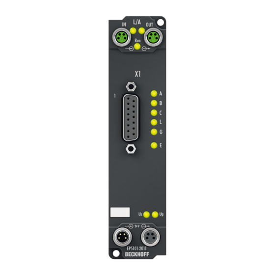
Page 22: Ep5101-2011 - Process Image
Product overview 2.4.6 EP5101-2011 - Process image TwinCAT shows the data of the EP5101-2011 in a tree structure. ENC Status Compact Status • Latch C valid New data are available in the process data Latch value. Reset via Enable latch C •... -
Page 23: Ep5151-0002 - Process Image
Product overview 2.4.7 EP5151-0002 - Process image ENC Status Compact Status • Latch C valid New data are available in the process data Latch value. Reset via Enable latch C • Latch extern valid New data are available in the process data Latch value. -
Page 24: Mounting And Connection
Mounting and connection Mounting and connection Mounting 3.1.1 Dimensions Fig. 5: Dimensions of the EtherCAT Box Modules All dimensions are given in millimeters. Housing properties EtherCAT Box lean body wide bodies Housing material PA6 (polyamide) Casting compound Polyurethane Mounting two fastening holes Ø 3 mm for M3 two fastening holes Ø 3 mm for M3 two fastening holes Ø 4.5 mm for M4 Metal parts... -
Page 25: Fixing
Mounting and connection 3.1.2 Fixing Note or pointer While mounting the modules, protect all connectors, especially the IP-Link, against contamination! Only with connected cables or plugs the protection class IP67 is guaranteed! Unused connectors have to be protected with the right plugs! See for plug sets in the catalogue. Modules with narrow housing are mounted with two M3 bolts. -
Page 26: Nut Torque For Connectors
Mounting and connection 3.1.3 Nut torque for connectors M8 connectors It is recommended to pull the M8 connectors tight with a nut torque of 0.4 Nm. When using the torque control screwdriver ZB8800 is also a max. torque of 0.5 Nm permissible. Fig. 7: EtherCAT Box with M8 connectors M12 connectors It is recommended to pull the M12 connectors tight with a nut torque of 0.6 Nm. -
Page 27: Additional Checks
Fig. 9: 7/8" plug connectors Torque socket wrenches Fig. 10: ZB8801 torque socket wrench Ensure the right torque Use the torque socket wrenches available by Beckhoff to pull the connectors tight (ZB8800, ZB8801-0000)! 3.1.4 Additional checks The boxes have undergone the following additional tests:... -
Page 28: Ethercat
Mounting and connection EtherCAT 3.2.1 EtherCAT connection For the incoming and ongoing EtherCAT connection, • the EtherCAT Box (EPxxxx) has two M8 sockets, marked in green • the Coupler Box (FBB-x110) has two M12 sockets Fig. 11: EtherCAT Box: M8, 30 mm housing Fig. 12: EtherCAT Box: M860 mm housing (example: EP9214) Fig. 13: Coupler Box: M12 Assignment... -
Page 29: Ethercat - Fieldbus Leds
M8 connectors were changed to the colors of EN61918 (yellow, orange, white, blue).So different color coding exists. But the electrical properties are absolutely identical. EtherCAT connector The following connectors can be supplied for use in Beckhoff EtherCAT systems. Name Connector... - Page 30 Mounting and connection LED display Display Meaning IN L/A no connection to the preceding EtherCAT module LINK: connection to the preceding EtherCAT module flashing ACT: Communication with the preceding EtherCAT module OUT L/A no connection to the following EtherCAT module LINK: connection to the following EtherCAT module flashing ACT: Communication with the following EtherCAT module...
-
Page 31: Power Supply
Mounting and connection Power supply 3.3.1 Power Connection The feeding and forwarding of supply voltages is done via two M8 connectors at the bottom end of the modules: • IN: left M8 connector for feeding the supply voltages • OUT: right M8 connector for forwarding the supply voltages Fig. 15: EtherCAT Box, Connectors for power supply Fig. 16: Pin assignment M8, Power In and Power Out Table 1: PIN assignment... - Page 32 Mounting and connection Auxiliary voltage Up 24 V The Auxiliary voltage Up supplies the digital outputs; it can be brought in separately. If the load voltage is switched off, the fieldbus functions and the power supply and functionality of the inputs are retained. Redirection of the supply voltages The IN and OUT power connections are bridged in the module (not IP204x-Bxxx and IE204x).
-
Page 33: Fig. 17 Ep92X4-0023, Connectors For Power In And Power Out
EP9214 or EP9224 (with integrated data logging, see www.beckhoff.com/EP9224) is recommended. With these modules intelligent power distribution concepts with up to 2 x 16 A and a maximum of 2.5 mm²... -
Page 34: Status Leds For Power Supply
Mounting and connection Electrical isolation Digital modules In the digital input/output modules, the grounds of the control voltage (GNDs) and the auxiliary voltage (GNDp) are connected to each other! Check this at the documentation of each used EtherCAT Box. Analog modules In the analog input/output modules the grounds of the control voltage (GNDs) and the auxiliary voltage (GNDp) are separated from each other in order to ensure electrical isolation of the analog signals from the control voltage. -
Page 35: Power Cable Conductor Losses M8
8 m power cable with 0.34 mm² cross-section has a voltage drop of 3.2 V at 4 A. EP92x4 Power Distribution Modules With EP9214 and EP9224 Power Distribution Modules intelligent concepts for voltage supply are available. Further information may be found under www.beckhoff.com/EP9224. EP5xxx Version: 2.3.0... -
Page 36: Conductor Losses 7/8
Mounting and connection 3.3.4 Conductor losses 7/8" In the case of the power cables ZK2030-xxxx-yyy, a total length of 15 m should not be exceeded at 16 A. When wiring, note that with a rated voltage of 24 V the function of the modules can no longer be guaranteed from a voltage drop of 6 V. -
Page 37: Cabling
Mounting and connection Cabling A list of EtherCAT cables, power cables, sensor cables, Ethernet/EtherCAT connectors and field- configurable connectors can be found under the following link: https://beckhoff.de/english/fieldbus_box/ ethercat_box_accessories_overview.htm?id=25525466903389 The corresponding data sheets can be found under the following link: https://beckhoff.de/english/ethercat-box/ethercat_box_cables.htm?id=690338951657421 EtherCAT cables Fig. 22: ZK1090-3131-0xxx... -
Page 38: Fig. 23 Zk2020-3132-0Xxx
Mounting and connection Power cable Fig. 23: ZK2020-3132-0xxx Sensor cables Fig. 24: Selection of Beckhoff sensor cables Version: 2.3.0 EP5xxx... -
Page 39: Shielding
Mounting and connection Shielding Shielding Encoder, analog sensors and actors should always be connected with shielded, twisted paired wires. UL Requirements The installation of the EtherCAT Box Modules certified by UL has to meet the following requirements. Supply voltage CAUTION CAUTION! This UL requirements are valid for all supply voltages of all marked EtherCAT Box Modules! For the compliance of the UL requirements the EtherCAT Box Modules should only be supplied... -
Page 40: Atex Notes
Mounting and connection ATEX notes 3.7.1 ATEX - Special conditions WARNING Observe the special conditions for the intended use of EtherCAT Box modules in poten- tially explosive areas – directive 94/9/EU. • The certified components are to be installed in the BG2000-0000 protection enclosure [} 41] that guar- antees a protection against mechanical hazards! •... -
Page 41: Bg2000-0000 - Ethercat Box Protection Enclosure
Mounting and connection 3.7.2 BG2000-0000 - EtherCAT Box protection enclosure WARNING Risk of electric shock and damage of device! Bring the EtherCAT system into a safe, powered down state before starting installation, disassembly or wiring of the modules! ATEX The BG2000-0000 protection enclosure has to be mounted over a single EtherCAT Box to fulfill the special conditions according to ATEX [} 40]. -
Page 42: Atex Documentation
Notes about operation of EtherCAT Box Modules (EPxxxx-xxxx) in potentially explo- sive areas (ATEX) Pay also attention to the continuative documentationNotes about operation of EtherCAT Box Mod- ules (EPxxxx-xxxx) in potentially explosive areas (ATEX) that is available in the download area of the Beckhoff homepage http:\\www.beckhoff.com! Version: 2.3.0 EP5xxx... -
Page 43: Signal Connection And Meaning Of The Leds
Mounting and connection Signal connection and meaning of the LEDs 3.8.1 EP5001-0002 - Signal connection Fig. 29: EP5001-0002, pin assignment M12 LED indicators - meanings Fig. 30: EP5001-0002, LEDs green Data Encoder supply switched on (operational SSI without power supply state, not short-circuited) Open circuit on the SSI data input D+ or D- Data cables interchanged The SSI input is at Low level, no data transfer takes... -
Page 44: Ep5101-X0Xx - Signal Connection
Mounting and connection 3.8.2 EP5101-x0xx - Signal connection Encoder pin assignment, M12, socket, 8-pin Fig. 31: EP5101-0002, EP5101-1002 pin assignment Fig. 32: EP5101-0002, EP5101-1002 LEDs LED indicators - meanings Connection LED Display Meaning Input A / track A low green Input A / track A high Input B / track B low green Input B / track B high... -
Page 45: Fig. 33 Ep5101-0011, Pin Assignment
Mounting and connection Encoder pin assignment, D-sub socket, 15-pin Fig. 33: EP5101-0011, pin assignment Fig. 34: EP5101-0011, LEDs LED indicators - meanings Connection Display Meaning D sub Input A / track A low green Input A / track A high Input B / track B low green Input B / track B high Input C / track C low... -
Page 46: Ep5151-0002 - Signal Connection
Mounting and connection 3.8.3 EP5151-0002 - Signal connection Encoder connection, M12 socket, 8-pin Fig. 35: EP5151-0002, pin assignment LED indicators - meanings Fig. 36: EP5151-0002, LEDs Connection LED Display Meaning Input A / track A low green Input A / track A high Input B / track B low green Input B / track B high... -
Page 47: Commissioning/Configuration
(default: C:\TwinCAT\IO\EtherCAT). The files are read (once) when a new System Man- ager window is opened. A TwinCAT installation includes the Beckhoff ESI files that were current at the time when the TwinCAT build was created. From TwinCAT 2.11 and in TwinCAT 3 the ESI di- rectory can be updated from the System Manager, if the programming PC is connected to the inter- net (TwinCAT →... -
Page 48: Fig. 37 Appending A New I/O Device (I/O Devices-> Right-Click -> Append Device
Commissioning/Configuration Adding a module manually • The EtherCAT system must be in a safe, de-energized state before you connect the EtherCAT modules to the EtherCAT network. • Switch on the operating voltage, open the TwinCAT System Manager [} 57] (Config mode) •... -
Page 49: Fig. 39 Appending A New Box (Device -> Right-Click -> Append Box
Commissioning/Configuration Fig. 39: Appending a new box (Device -> right-click -> Append Box... ) • In the dialog that is displayed select the required Box (e.g. EP6224-2022) and confirm with OK. Fig. 40: Selecting a Box (e.g. EP6224-2022) EP5xxx Version: 2.3.0... -
Page 50: Configuration Setup: Twincat - Online Scan
(default: C:\TwinCAT\IO\EtherCAT). The files are read (once) when a new System Man- ager window is opened. A TwinCAT installation includes the Beckhoff ESI files that were current at the time when the TwinCAT build was created. From TwinCAT 2.11 and in TwinCAT 3 the ESI di- rectory can be updated from the System Manager, if the programming PC is connected to the inter- net (TwinCAT →... -
Page 51: Fig. 41 Twincat Config Mode Display
Commissioning/Configuration • The actual EtherCAT and IO-Link hardware (devices, couplers, drives) must be present and installed. • The devices/modules must be connected via an EtherCAT cables or an IO-Link cable in the same way as they are intended to be used later. •... -
Page 52: Fig. 42 Scan Devices
Commissioning/Configuration Fig. 42: Scan Devices This scan mode not only tries to find EtherCAT devices (or Ethernet ports that can be used as such), but also NOVRAM, fieldbus cards, SMB etc. Not all devices can be found automatically. Fig. 43: Note for automatic device scan Ethernet ports with installed TwinCAT real-time driver are shown as “RT Ethernet”... -
Page 53: Fig. 45 Scan Query After Automatic Creation Of An Ethercat Device
Commissioning/Configuration Detecting/Scanning the EtherCAT devices Online scan functionality During a scan the master queries the identity information of the EtherCAT device from the device EEPROM. The name and revision are used for determining the type. The respective devices are lo- cated in the stored ESI data and integrated in the configuration tree in the default state defined there. -
Page 54: Fig. 47 Master Display After "Scan For Boxes
Commissioning/Configuration The connected EtherCAT Box (EP6224-3022) is displayed in the TwinCAT tree, as shown in the following illustration. Fig. 47: Master display after “Scan for boxes” Troubleshooting Various effects may occur during scanning. • An unknown device is detected, i.e. an EtherCAT device for which no ESI XML description is available. -
Page 55: Fig. 49 Example Correction Dialog
If current ESI descriptions are available in the TwinCAT system, the last revision offered in the se- lection dialog matches the Beckhoff state of production. It is recommended to use the last device re- vision when creating a new configuration, if current Beckhoff devices are used in the real applica- tion. -
Page 56: Fig. 50 Example Correction Dialog With Modifications
Commissioning/Configuration Fig. 50: Example correction dialog with modifications Once all modifications have been saved or accepted, click “OK” to transfer them to the real *.tsm configuration. Version: 2.3.0 EP5xxx... -
Page 57: Configuration Via Twincat
Commissioning/Configuration Configuration via TwinCAT In the left-hand window of the TwinCAT System Manager, click on the branch of the EtherCAT Box you wish to configure (EP2816-0008 in this example). Fig. 51: Branch of the EtherCAT box to be configured In the right-hand window of the TwinCAT System manager, various tabs are now available for configuring the EtherCAT Box. -
Page 58: Fig. 53 Ethercat Tab
Commissioning/Configuration EtherCAT tab Fig. 53: EtherCAT tab Type EtherCAT device type Product/Revision Product and revision number of the EtherCAT device Auto Inc Addr. Auto increment address of the EtherCAT device. The auto increment address can be used for addressing each EtherCAT device in the communication ring through its physical position. -
Page 59: Fig. 54 Process Data Tab
Commissioning/Configuration Fig. 54: Process Data tab Sync Manager Lists the configuration of the Sync Manager (SM). If the EtherCAT device has a mailbox, SM0 is used for the mailbox output (MbxOut) and SM1 for the mailbox input (MbxIn). SM2 is used for the output process data (outputs) and SM3 (inputs) for the input process data. If an input is selected, the corresponding PDO assignment is displayed in the PDO Assignment list below. - Page 60 Commissioning/Configuration Activation of PDO assignment • the EtherCAT slave has to run through the PS status transition cycle (from pre-operational to safe-operational) once (see Online tab [} 63]), • and the System Manager has to reload the EtherCAT slaves ( button) PDO list List of all PDOs supported by this EtherCAT device.
-
Page 61: Fig. 55 Startup Tab
Commissioning/Configuration Fig. 55: Startup tab Column Description Transition Transition to which the request is sent. This can either be • the transition from pre-operational to safe-operational (PS), or • the transition from safe-operational to operational (SO). If the transition is enclosed in "<>" (e.g. <PS>), the mailbox request is fixed and cannot be modified or deleted by the user. -
Page 62: Fig. 56 Coe - Online Tab
Commissioning/Configuration Fig. 56: CoE - Online tab Object list display Column Description Index Index and subindex of the object Name Name of the object Flags The object can be read, and data can be written to the object (read/write) The object can be read, but no data can be written to the object (read only) An additional P identifies the object as a process data object. -
Page 63: Fig. 57 Advanced Settings
Commissioning/Configuration Fig. 57: Advanced settings Online If this option button is selected, the list of the objects included in the object - via SDO information directory of the slave is uploaded from the slave via SDO information. The list below can be used to specify which object types are to be uploaded. Offline If this option button is selected, the list of the objects included in the object - via EDS file... - Page 64 Commissioning/Configuration State Machine Init This button attempts to set the EtherCAT device to the Init state. Pre-Op This button attempts to set the EtherCAT device to the pre-operational state. This button attempts to set the EtherCAT device to the operational state. Bootstrap This button attempts to set the EtherCAT device to the Bootstrap state.
-
Page 65: Ethercat Slave Process Data Settings (Pdo)
To this end the EtherCAT master (Beckhoff TwinCAT) parameterizes each EtherCAT slave during the start-up phase to define which process data (size in bits/bytes, source location, transmission type) it wants to transfer to or from this slave. -
Page 66: Ep5001-0002 - Parameters And Modes
Commissioning/Configuration Manual modification of the process data According to the ESI description, a PDO can be identified as "fixed" with a flag "F" in the PDO over- view (see previous illustration, J). The configuration of such PDOs cannot be changed, even if Twin- CAT offers the associated dialog (“Edit”). -
Page 67: Fig. 60 Ep5001-0002
Commissioning/Configuration 4.5.1.1 EP5001-0002 - PDO assignment Fig. 61: PDO assignment and content; example: EP5001-0002 The PDO 0x1A00 configuration of the EP5001-0002 cannot be changed. PDO Assignment SM3, PDO Assignment 0x1C13 Index Index of excluded Size Name PDO Content PDOs (byte.bit) (index - name) 0x1A00 SSI Inputs 0x6000:01 [} 94] - Data error... -
Page 68: Dc (Distributed Clocks)
Commissioning/Configuration 4.5.2 DC (Distributed Clocks) Describes whether the module is operated with support from distributed clocks: Fig. 62: Distributed Clocks • FreeRun: The module operates frame-triggered. Cyclic operation is started via the SyncManagers during EtherCAT frame processing. • DC-Synchron: Cyclic operation in the module is started by the local distributed clock at exact intervals. The start time is chosen such that it coincides with other output slaves in the EtherCAT system. -
Page 69: Features Coe
Commissioning/Configuration 4.5.3 Features CoE Further settings can be selected in the CoE (CAN over EtherCAT)-list. Parameterization via the CoE list (CAN over EtherCAT) Please note the following general CoE notes when using/manipulating the CoE parameters: • Keep a startup list if components have to be replaced •... - Page 70 Commissioning/Configuration • Index 0x8000:13 [} 94], Min. Inhibit time [µs] See index 0x8000:03 [} 94]. SSI advanced settings • Index 0x800D:01 [} 95], Encoder power supply on Switches the 24 V supply voltage • Index 0x800D:02 [} 95], Encoder direction pin on Switches the 24 V supply at the Direction pin •...
-
Page 71: Ep51X1-X0Xx - Parameters And Modes
Commissioning/Configuration EP51x1-x0xx - Parameters and modes 4.6.1 Process data 16 or 32 bit process data The EP51x1 can be operated both with 16 bit process data (default) or 32 bit process data. This can be set via the Predefined PDO Assignment in the Process Data table tab. Fig. 64: 16 or 32 bit process data Main PDO Selection of basic process data... -
Page 72: Fig. 65 Main Pdo, Example: Ep5101-0011
Commissioning/Configuration Fig. 65: Main PDO, example: EP5101-0011 A: Selection of data direction: input or output C: Explanatory notes for PDOs B: Selection of (optional) PDOs (process data D: PDO content objects) • compact: The process data can be represented with 16 bits (compact) or with 32 bits. Optional PDOs Optional PDOs, in addition to the main PDO: •... -
Page 73: Fig. 66 Pdo Assignment And Content; Example: Ep5101-0002
Commissioning/Configuration 4.6.1.1 EP5101-x002 - PDO assignment Fig. 66: PDO assignment and content; example: EP5101-0002 PDO Assignment To configure the process data, select the required Sync Manager (SM 2 or SM 3 can be changed) in the Sync Manager field at the top left (see illustration above). The process data assigned to this Sync Manager can then be switched on or off in the PDO Assignment field below. - Page 74 Commissioning/Configuration SM3, PDO Assignment 0x1C13 Index Index of excluded Size Name PDO Content PDOs (byte.bit) (index - name) 0x1A00 0x1A01 ENC Status compact 0x6000:01 [} 98] - Latch C valid (default) 0x6000:03 [} 98] - Set counter done 0x6000:04 [} 98] - Counter underflow 0x6000:05 [} 98] - Counter overflow 0x6000:07 [} 98] - Open circuit 0x6000:08 [} 98] - Extrapolation stall...
-
Page 75: Fig. 67 Pdo Assignment And Content; Example: Ep5101-0011
Commissioning/Configuration 4.6.1.2 EP5101-0011 - PDO assignment Fig. 67: PDO assignment and content; example: EP5101-0011 PDO Assignment To configure the process data, select the required Sync Manager (SM 2 or SM 3 can be changed) in the Sync Manager field at the top left (see illustration above). The process data assigned to this Sync Manager can then be switched on or off in the PDO Assignment field below. - Page 76 Commissioning/Configuration SM2, PDO Assignment 0x1C12 Index Index of excluded Size Name PDO Content PDOs (byte.bit) (index - name) 0x1600 0x1601 ENC Control 0x7000:01 [} 115] - Enable Latch C (default) compact 0x7000:02 [} 115] - Enable Latch extern on positive edge 0x7000:03 [} 115] - Set counter 0x7000:04 [} 115] - Enable Latch extern on negative edge 0x7000:11 [} 115] - Set counter value (16-bit) 0x1601...
-
Page 77: Fig. 68 Pdo Assignment And Content, Ep5101-2011
Commissioning/Configuration 4.6.1.3 EP5101-2011 - PDO assignment Fig. 68: PDO assignment and content, EP5101-2011 PDO Assignment To configure the process data, select the required Sync Manager (SM 2 or SM 3 can be changed) in the Sync Manager field at the top left (see illustration above). The process data assigned to this Sync Manager can then be switched on or off in the PDO Assignment field below. - Page 78 Commissioning/Configuration SM2, PDO Assignment 0x1C12 Index Index of excluded Size Name PDO Content PDOs (byte.bit) (index - name) 0x1600 0x1601 ENC Control 0x7000:01 [} 127] - Enable Latch C 0x7000:02 [} 127] - Enable Latch extern on positive edge 0x7000:03 [} 127] - Set counter 0x7000:04 [} 127] - Enable Latch extern on negative edge 0x7000:11 [} 127] - Set counter value (32-bit) 0x1601...
-
Page 79: Fig. 69 Pdo Assignment And Content; Example: Ep5151-0002
Commissioning/Configuration 4.6.1.4 EP5151-0002 - PDO assignment Fig. 69: PDO assignment and content; example: EP5151-0002 PDO Assignment To configure the process data, select the required Sync Manager (SM 2 or SM 3 can be changed) in the Sync Manager field at the top left (see illustration above). The process data assigned to this Sync Manager can then be switched on or off in the PDO Assignment field below. - Page 80 Commissioning/Configuration SM2, PDO Assignment 0x1C12 Index Index of excluded Size Name PDO Content PDOs (byte.bit) (index - name) 0x1600 0x1601 ENC Control 0x7000:01 [} 140] - Enable Latch C (default) compact 0x7000:02 [} 140] - Enable Latch extern on positive edge 0x7000:03 [} 140] - Set counter 0x7000:04 [} 140] - Enable Latch extern on negative edge 0x7000:11 [} 140] - Set counter value (16-bit) 0x1601...
-
Page 81: Dc (Distributed Clocks)
Commissioning/Configuration 4.6.2 DC (Distributed Clocks) Describes whether the module is operated with support from distributed clocks: Fig. 70: Distributed Clocks • FreeRun: The module operates frame-triggered. Cyclic operation is started via the SyncManagers during EtherCAT frame processing. • DC-Synchron: Cyclic operation in the module is started by the local distributed clock at exact intervals. The start time is chosen such that it coincides with other output slaves in the EtherCAT system. -
Page 82: Features Coe
Commissioning/Configuration 4.6.3 Features CoE Depending on the main PDO/optional PDOs further settings can be selected in the CoE list (CAN over EtherCAT). Parameterization via the CoE list (CAN over EtherCAT) Please note the following general CoE notes when using/manipulating the CoE parameters: •... -
Page 83: Fig. 72 Frequency Measurement Principle In Enhanced Operation Mode
Commissioning/Configuration Additional Notes Frequency • The time window for the frequency calculation and the resolution can be parameterized in the CoE objects Frequency window 0x8000:11, Frequency scaling 0x8000:13, Frequency resolution 0x8000:15 and Frequency wait time 0x8000:17. • The positive edges of track A are counted within the specified timeframe and the next edge including the time up to it are counted. - Page 84 Commissioning/Configuration Latch • Activation of latch C input (Enable latch C index 0x7000:01) and saving ("latching") of the counter value ◦ The counter value is saved when the first external latch pulse (positive edge at input "C") is encountered after the bit has been set (TRUE) in Enable latch C index 0x7000:01 (this has priority over Enable latch extern on positive / negative edge 0x7000:02 / 0x7000:04).
- Page 85 Commissioning/Configuration Overflow/underflow (not for EP5101-2011) • Overflow/underflow control is inactive in combination with an activated reset function (C/external). • The underflow bit (0x6000:04) is set if an underflow ...00 ->...FF occurs. It is reset if 2/3 of the counter range are underrun. •...
-
Page 86: Fig. 73 Dc-Supported Micro-Increments
Commissioning/Configuration Fig. 73: DC-supported micro-increments The highly constant query cycles (accuracy: 100 ns) of the distributed clocks systems enable the EP51x1 to interpolate axis positions between the counted encoder increments from a certain speed. The interpolation resolution is 8 bit, corresponding to 256 values. A standard encoder with 1,024 lines with 4-way evaluation and micro-increments thus becomes a high-resolution axis encoder with 4096 x 256 = 1,048,567 lines. -
Page 87: Ep5001 - Interface Signal Level
Commissioning/Configuration EP5001 - Interface signal level The EP5001-0002 expects signal levels according to RS485. The typical output levels apply for a load of 60 ohm or higher. Differential signal input Fig. 74: Voltage level for differential mode The EP5001-0002 does not support single-ended mode. EP5xxx Version: 2.3.0... -
Page 88: Ep5101 - Interface Signal Level
Commissioning/Configuration EP5101 - Interface signal level In differential mode, the EP5101-x00x expects signal levels according to RS422. The data are transferred without ground reference as voltage difference between two cables (signal A and inverted signal /A). The module analyses signal levels in the range -200mV < Vid < +200mV as valid signals. The differential signal must be in the common mode range (<+13.2 V and >-10 V, with respect to GND) (cf. -
Page 89: Ep5151 - Interface Signal Level
Commissioning/Configuration EP5151 - Interface signal level The EP5151 expects signal levels according to HTL (push-pull). Differential signal input Fig. 76: Voltage level for differential mode EP5xxx Version: 2.3.0... -
Page 90: Ep5001-0002 - Object Description And Parameterization
EtherCAT XML Device Description The display matches that of the CoE objects from the EtherCAT XML Device Description. We rec- ommend downloading the latest XML file from the download area of the Beckhoff website and in- stalling it according to installation instructions. - Page 91 Commissioning/Configuration Index 1018 Identity Index (hex) Name Meaning Data type Flags Default 1018:0 Identity Information for identifying the slave UINT8 0x04 (4 1018:01 Vendor ID Vendor ID of the EtherCAT slave UINT32 0x00000002 1018:02 Product code Product code of the EtherCAT slave UINT32 0x13894052 (327762002...
- Page 92 Commissioning/Configuration Index 1C12 RxPDO assign Index (hex) Name Meaning Data type Flags Default 1C12:0 RxPDO assign PDO Assign Outputs UINT8 0x00 (0 Index 1C13 TxPDO assign Index (hex) Name Meaning Data type Flags Default 1C13:0 TxPDO assign PDO Assign Inputs UINT8 0x02 (2 1C13:01...
- Page 93 Commissioning/Configuration Index 1C33 SM input parameter Index (hex) Name Meaning Data type Flags Default 1C33:0 SM input parameter Synchronization parameters for the inputs UINT8 0x20 (32 1C33:01 Sync mode Current synchronization mode: UINT16 0x0022 (34 • 0: Free Run • 1: Synchron with SM 3 Event (no outputs available) •...
- Page 94 Commissioning/Configuration Index 6000 SSI Inputs Index (hex) Name Meaning Data type Flags Default 6000:0 SSI Inputs Length of this object UINT8 0x11 (17 6000:01 Data error SSI input error: BOOLEAN 0x00 (0 - SSI without power supply - Broken wire at SSI data inputs D+ or D- - Data cables interchanged If no data communication takes place the SSI input of the terminal is on low level.
- Page 95 Commissioning/Configuration Index 800D SSI Advanced Settings Index (hex) Name Meaning Data type Flags Default 800D:0 SSI advanced set- SSI advanced settings 0x03 (3 tings 800D:01 Encoder power sup- Switches the 24 V supply voltage 0x01 (1 ply on 800D:02 Encoder direction Switches the 24 V supply at the direction pin 0x00 (0 pin on...
-
Page 96: Ep5101-0002, Ep5101-1002 - Object Description And Parameterization - Normal Operating Mode
EtherCAT XML Device Description The display matches that of the CoE objects from the EtherCAT XML Device Description. We rec- ommend downloading the latest XML file from the download area of the Beckhoff website and in- stalling it according to installation instructions. -
Page 97: Configuration Data
Commissioning/Configuration 4.11.2 Configuration data Index 8000 ENC Settings Index (hex) Name Meaning Data type Flags Default 8000:0 ENC Settings Maximum subindex UINT8 0x17 (23 8000:01 Enable C reset [} 84] The counter is reset via the C input. BOOLEAN 0x00 (0 8000:03 Enablement of the up/down counter in place of the encoder BOOLEAN... -
Page 98: Input Data
Commissioning/Configuration Index (hex) Name Meaning Data type Flags Default 8000:17 Waiting time [ms] for frequency measurement UINT16 0x0640 Frequency wait time Once the time specified in the frequency window has (1600 [} 83] elapsed, the system waits for the next positive edge from track A. -
Page 99: Output Data
Commissioning/Configuration 4.11.4 Output data Index 7000 ENC Outputs Index (hex) Name Meaning Data type Flags Default 7000:0 ENC Outputs Maximum subindex UINT8 0x11(17 7000:01 Enable latch C [} 84] Activate latching via input “C”. BOOLEAN 0x00 (0 7000:03 Set counter Set counter value BOOLEAN 0x00 (0 7000:11... - Page 100 Commissioning/Configuration Index 1018 Identity Index (hex) Name Meaning Data type Flags Default 1018:0 Identity Information for identifying the slave UINT8 0x04 (4 1018:01 Vendor ID Vendor ID of the EtherCAT slave UINT32 0x00000002 1018:02 Product code Product code of the EtherCAT slave UINT32 0x13ED4052 (334315602...
- Page 101 Commissioning/Configuration Index 1600 ENC RxPDO-Map Control compact (EP5101-1002) Index (hex) Name Meaning Data type Flags Default 1600:0 ENC RxPDO-Map PDO Mapping RxPDO 3 UINT8 0x07 (7 Control compact 1600:01 SubIndex 001 1. PDO Mapping entry (object 0x7000 (ENC Outputs), en- UINT32 0x7000:01,1 try 0x01 (Enable latch C))
- Page 102 Commissioning/Configuration Index 1801 ENC TxPDO-Par Status Index (hex) Name Meaning Data type Flags Default 1801:0 ENC TxPDO-Par PDO parameter TxPDO 2 UINT8 0x09 (9 Status 1801:06 Exclude TxPDOs Specifies the TxPDOs (index of TxPDO mapping objects) OCTET- 00 1A that must not be transferred together with TxPDO 2. STRING[2] 1801:07 TxPDO State...
- Page 103 Commissioning/Configuration Index 1A00 ENC TxPDO-Map Status compact (EP5101-0002) Index (hex) Name Meaning Data type Flags Default 1A00:0 ENC TxPDO-Map ENC TxPDO-Map Status compact UINT8 0x011 (17 Status compact 1A00:01 SubIndex 001 1. PDO Mapping entry (object 0x6000 (ENC Inputs), entry UINT32 0x6000:01, 1 0x01 (Latch C valid))
- Page 104 Commissioning/Configuration Index 1A00 ENC TxPDO-Map Status compact (EP5101-1002) Index (hex) Name Meaning Data type Flags Default 1A00:0 ENC TxPDO-Map ENC TxPDO-Map Status compact UINT8 0x012 (18 Status compact 1A00:01 SubIndex 001 1. PDO Mapping entry (object 0x6000 (ENC Inputs), entry UINT32 0x6000:01, 1 0x01 (Latch C valid))
- Page 105 Commissioning/Configuration Index 1A01 ENC TxPDO-Map Status (EP5101-0002) Index (hex) Name Meaning Data type Flags Default 1A01:0 ENC TxPDO-Map ENC TxPDO-Map Status UINT8 0x11 (17 Status compact 1A01:01 SubIndex 001 1. PDO Mapping entry (object 0x6000 (ENC Inputs), entry UINT32 0x6000:01, 1 0x01 (Latch C valid)) 1A01:02 SubIndex 002...
- Page 106 Commissioning/Configuration Index 1A01 ENC TxPDO-Map Status (EP5101-1002) Index (hex) Name Meaning Data type Flags Default 1A01:0 ENC TxPDO-Map ENC TxPDO-Map Status UINT8 0x12 (18 Status compact 1A01:01 SubIndex 001 1. PDO Mapping entry (object 0x6000 (ENC Inputs), entry UINT32 0x6000:01, 1 0x01 (Latch C valid)) 1A01:02 SubIndex 002...
- Page 107 Commissioning/Configuration Index 1A05 ENC TxPDO-Map Timest. compact Index (hex) Name Meaning Data type Flags Default 1A05:0 ENC TxPDO-Map ENC TxPDO-Map Timest. compact UINT8 0x01 (1 Timest. compact 1A05:01 SubIndex 001 1. PDO Mapping entry (object 0x6000 (ENC Inputs), entry UINT32 0x6000:16, 32 0x16 (Timestamp)) Index 1C00 Sync manager type...
- Page 108 Commissioning/Configuration Index 1C32 SM output parameter Index (hex) Name Meaning Data type Flags Default 1C32:0 SM output parame- Synchronization parameters for the outputs UINT8 0x20 (32 1C32:01 Sync mode Current synchronization mode: UINT16 0x0001 (1 • 0: Free Run • 1: Synchron with SM 2 Event •...
- Page 109 Commissioning/Configuration Index 1C33 SM input parameter Index (hex) Name Meaning Data type Flags Default 1C33:0 SM input parameter Synchronization parameters for the inputs UINT8 0x20 (32 1C33:01 Sync mode Current synchronization mode: UINT16 0x0022 (34 • 0: Free Run • 1: Synchron with SM 3 Event (no outputs available) •...
- Page 110 Commissioning/Configuration Index F010 Module list Index (hex) Name Meaning Data type Flags Default F010:0 Module list Maximum subindex UINT8 0x02 (2 F010:01 SubIndex 001 reserved UINT32 0x000001FE (510 Version: 2.3.0 EP5xxx...
-
Page 111: Ep5101-0011 - Object Description And Parameterization - Normal Operating Mode
EtherCAT XML Device Description The display matches that of the CoE objects from the EtherCAT XML Device Description. We rec- ommend downloading the latest XML file from the download area of the Beckhoff website and in- stalling it according to installation instructions. -
Page 112: Configuration Data
Commissioning/Configuration 4.12.2 Configuration data Index 8000 ENC Settings Index (hex) Name Meaning Data type Flags Default 8000:0 ENC Settings Maximum subindex UINT8 0x17 (23 8000:01 Enable C reset [} 84] The counter is reset via the C input. BOOLEAN 0x00 (0 8000:02 A counter reset is triggered via the external latch input BOOLEAN... - Page 113 Commissioning/Configuration Index (hex) Name Meaning Data type Flags Default 8000:16 Internal resolution of the period measurement: 100: UINT16 0x0064 (100 Period resolution “100 ns” period value is a multiple of 100 ns [} 83] The period is calculated internally with a resolution of 100 ns. The max. measurable period can then be approx. 1.6 seconds.
-
Page 114: Input Data
Commissioning/Configuration 4.12.3 Input data Index 6000 ENC Inputs Index (hex) Name Meaning Data type Flags Default 6000:0 ENC Inputs Maximum subindex UINT8 0x16 (22 6000:01 The counter value was latched with the “C” input. The data BOOLEAN 0x00 (0 Latch C valid [} 84] with Latch Value (Index 0x6000:12) corresponds to the latched value if the bit is set. -
Page 115: Output Data
Commissioning/Configuration 4.12.4 Output data Index 7000 ENC Outputs Index (hex) Name Meaning Data type Flags Default 7000:0 ENC Outputs Maximum subindex UINT8 0x11(17 7000:01 Enable latch C [} 84] Activate latching via input “C”. BOOLEAN 0x00 (0 7000:01 Activate external latch with positive edge. BOOLEAN 0x00 (0 Enable latch extern... - Page 116 Commissioning/Configuration Index 1018 Identity Index (hex) Name Meaning Data type Flags Default 1018:0 Identity Information for identifying the slave UINT8 0x04 (4 1018:01 Vendor ID Vendor ID of the EtherCAT slave UINT32 0x00000002 1018:02 Product code Product code of the EtherCAT slave UINT32 0x13ED4052 (334315602...
- Page 117 Commissioning/Configuration Index 1601 ENC RxPDO-Map Control Index (hex) Name Meaning Data type Flags Default 1601:0 ENC RxPDO-Map PDO Mapping RxPDO UINT8 0x07 (7 Control compact 1601:01 SubIndex 001 1. PDO Mapping entry (object 0x7000 (ENC Outputs), en- UINT32 0x7000:01,1 try 0x01 (Enable latch C)) 1601:02 SubIndex 002 2.
- Page 118 Commissioning/Configuration Index 1805 ENC TxPDO-Par Timest. compact Index (hex) Name Meaning Data type Flags Default 1805:0 ENC TxPDO-Par PDO parameter TxPDO 6 UINT8 0x06 (6 Timest. compact 1805:06 Exclude TxPDOs Specifies the TxPDOs (index of TxPDO mapping objects) OCTET- 04 1A that must not be transferred together with TxPDO 6 STRING[2] Index 1A00 ENC TxPDO-Map Status compact...
- Page 119 Commissioning/Configuration Index 1A01 ENC TxPDO-Map Status Index (hex) Name Meaning Data type Flags Default 1A01:0 ENC TxPDO-Map PDO Mapping TxPDO 2 UINT8 0x12 (18 Status compact 1A01:01 SubIndex 001 1. PDO Mapping entry (object 0x6000 (ENC Inputs), entry UINT32 0x6000:01, 1 0x01 (Latch C valid)) 1A01:02 SubIndex 002...
- Page 120 Commissioning/Configuration Index 1A05 ENC TxPDO-Map Timest. compact Index (hex) Name Meaning Data type Flags Default 1A05:0 ENC TxPDO-Map PDO Mapping TxPDO UINT8 0x01 (1 Timest. compact 1A05:01 SubIndex 001 1. PDO Mapping entry (object 0x6010 (ENC Inputs), UINT32 0x6000:16, 32 entry 0x16 (Timestamp)) Index 1C00 Sync manager type Index (hex) Name...
- Page 121 Commissioning/Configuration Index 1C32 SM output parameter Index (hex) Name Meaning Data type Flags Default 1C32:0 SM output parameter Synchronization parameters for the outputs UINT8 0x20 (32 1C32:01 Sync mode Current synchronization mode: UINT16 0x0001 (1 • 0: Free Run • 1: Synchron with SM 2 Event •...
- Page 122 Commissioning/Configuration Index 1C33 SM input parameter Index (hex) Name Meaning Data type Flags Default 1C33:0 SM input parameter Synchronization parameters for the inputs UINT8 0x20 (32 1C33:01 Sync mode Current synchronization mode: UINT16 0x0022 (34 • 0: Free Run • 1: Synchron with SM 3 Event (no outputs available) •...
- Page 123 Commissioning/Configuration Index F010 Module list Index (hex) Name Meaning Data type Flags Default F010:0 Module list Maximum subindex UINT8 0x02 (2 F010:01 SubIndex 001 reserved UINT32 0x000001FE (510 F010:02 SubIndex 002 reserved UINT32 0x000001FF (511 EP5xxx Version: 2.3.0...
-
Page 124: Ep5101-2011 - Object Description And Parameterization - Normal Operating Mode
EtherCAT XML Device Description The display matches that of the CoE objects from the EtherCAT XML Device Description. We rec- ommend downloading the latest XML file from the download area of the Beckhoff website and in- stalling it according to installation instructions. -
Page 125: Configuration Data
Commissioning/Configuration 4.13.2 Configuration data Index 8000 ENC Settings Index (hex) Name Meaning Data type Flags Default 8000:0 ENC Settings Maximum subindex UINT8 0x17 (23 8000:01 Enable C reset [} 84] The counter is reset via the C input. BOOLEAN 0x00 (0 8000:02 A counter reset is triggered via the external latch input BOOLEAN... -
Page 126: Input Data
Commissioning/Configuration Index (hex) Name Meaning Data type Flags Default 8000:17 Waiting time [ms] for frequency measurement UINT16 0x0640 Frequency wait time Once the time specified in the frequency window has (1600 [} 83] elapsed, the system waits for the next positive edge from track A. -
Page 127: Output Data
Commissioning/Configuration 4.13.4 Output data Index 7000 ENC Outputs Index (hex) Name Meaning Data type Flags Default 7000:0 ENC Outputs Maximum subindex UINT8 0x11(17 7000:01 Enable latch C [} 84] Activate latching via input “C”. BOOLEAN 0x00 (0 7000:02 Activate external latch with positive edge. BOOLEAN 0x00 (0 Enable latch extern... - Page 128 Commissioning/Configuration Index 1018 Identity Index (hex) Name Meaning Data type Flags Default 1018:0 Identity Information for identifying the slave UINT8 0x04 (4 1018:01 Vendor ID Vendor ID of the EtherCAT slave UINT32 0x00000002 1018:02 Product code Product code of the EtherCAT slave UINT32 0x13ED4052 (334315602...
- Page 129 Commissioning/Configuration Index 1601 ENC RxPDO-Map Control compact Index (hex) Name Meaning Data type Flags Default 1601:0 ENC RxPDO-Map PDO Mapping RxPDO UINT8 0x07 (7 Control compact 1601:01 SubIndex 001 1. PDO Mapping entry (object 0x7000 (ENC Outputs), en- UINT32 0x7000:01,1 try 0x01 (Enable latch C)) 1601:02 SubIndex 002...
- Page 130 Commissioning/Configuration Index 1A00 ENC TxPDO-Map Status Index (hex) Name Meaning Data type Flags Default 1A00:0 ENC TxPDO-Map ENC TxPDO-Map Status compact UINT8 0x011 (17 Status 1A00:01 SubIndex 001 1. PDO Mapping entry (object 0x6000 (ENC Inputs), entry UINT32 0x6000:01, 1 0x01 (Latch C valid)) 1A00:02 SubIndex 002...
- Page 131 Commissioning/Configuration Index 1A01 ENC TxPDO-Map Status compact Index (hex) Name Meaning Data type Flags Default 1A01:0 ENC TxPDO-Map PDO Mapping TxPDO 2 UINT8 0x11 (17dec) Status compact 1A01:01 SubIndex 001 1. PDO Mapping entry (object 0x6000 (ENC Inputs), entry UINT32 0x6000:01, 1 0x01 (Latch C valid)) 1A01:02...
- Page 132 Commissioning/Configuration Index 1A05 ENC TxPDO-Map Timest. compact Index (hex) Name Meaning Data type Flags Default 1A05:0 ENC TxPDO-Map PDO Mapping TxPDO UINT8 0x01 (1 Timest. compact 1A05:01 SubIndex 001 1. PDO Mapping entry (object 0x6000 (ENC Inputs), entry UINT32 0x6000:16, 32 0x16 (Timestamp)) Index 1C00 Sync manager type Index (hex) Name...
- Page 133 Commissioning/Configuration Index 1C32 SM output parameter Index (hex) Name Meaning Data type Flags Default 1C32:0 SM output parame- Synchronization parameters for the outputs UINT8 0x20 (32 1C32:01 Sync mode Current synchronization mode: UINT16 0x0001 (1 • 0: Free Run • 1: Synchron with SM 2 Event •...
- Page 134 Commissioning/Configuration Index 1C33 SM input parameter Index (hex) Name Meaning Data type Flags Default 1C33:0 SM input parameter Synchronization parameters for the inputs UINT8 0x20 (32 1C33:01 Sync mode Current synchronization mode: UINT16 0x0022 (34 • 0: Free Run • 1: Synchron with SM 3 Event (no outputs available) •...
- Page 135 Commissioning/Configuration Index F010 Module list Index (hex) Name Meaning Data type Flags Default F010:0 Module list Maximum subindex UINT8 0x02 (2 F010:01 SubIndex 001 reserved UINT32 0x000001FF (511 EP5xxx Version: 2.3.0...
-
Page 136: Ep5151-0002 - Object Description And Parameterization - Normal Operating Mode
EtherCAT XML Device Description The display matches that of the CoE objects from the EtherCAT XML Device Description. We rec- ommend downloading the latest XML file from the download area of the Beckhoff website and in- stalling it according to installation instructions. -
Page 137: Configuration Data
Commissioning/Configuration 4.14.2 Configuration data Index 8000 ENC Settings Index (hex) Name Meaning Data type Flags Default 8000:0 ENC Settings Maximum subindex UINT8 0x17 (23 8000:01 Enable C reset [} 84] The counter is reset via the C input. BOOLEAN 0x00 (0 8000:02 A counter reset is triggered via the external latch input BOOLEAN... - Page 138 Commissioning/Configuration Index (hex) Name Meaning Data type Flags Default 8000:16 Internal resolution of the period measurement: 100: UINT16 0x0064 (100 Period resolution “100 ns” period value is a multiple of 100 ns [} 83] The period is calculated internally with a resolution of 100 ns. The max. measurable period can then be approx. 1.6 seconds.
-
Page 139: Input Data
Commissioning/Configuration 4.14.3 Input data Index 6000 ENC Inputs Index (hex) Name Meaning Data type Flags Default 6000:0 ENC Inputs Maximum subindex UINT8 0x16 (22 6000:01 The counter value was latched with the “C” input. The data BOOLEAN 0x00 (0 Latch C valid [} 84] with Latch Value (Index 0x6000:12) corresponds to the latched value if the bit is set. -
Page 140: Output Data
Commissioning/Configuration 4.14.4 Output data Index 7000 ENC Outputs Index (hex) Name Meaning Data type Flags Default 7000:0 ENC Outputs Maximum subindex UINT8 0x11(17 7000:01 Enable latch C [} 84] Activate latching via input “C”. BOOLEAN 0x00 (0 7000:01 Activate external latch with positive edge. BOOLEAN 0x00 (0 Enable latch extern... - Page 141 Commissioning/Configuration Index 10F0 Backup parameter handling Index (hex) Name Meaning Data type Flags Default 10F0:0 Backup parameter Information for standardized loading and saving of backup UINT8 0x01 (1 handling entries 10F0:01 Checksum Checksum across all backup entries of the EtherCAT slave UINT32 0x00000000 Index 1400 ENC RxPDO-Par Control compact Index (hex) Name...
- Page 142 Commissioning/Configuration Index 1800 ENC TxPDO-Par Status compact Index (hex) Name Meaning Data type Flags Default 1800:0 ENC TxPDO-Par PDO parameter TxPDO 1 UINT8 0x09 (9 Status compact 1800:06 Exclude TxPDOs Specifies the TxPDOs (index of TxPDO mapping objects) OCTET- 01 1A that must not be transferred together with TxPDO 1.
- Page 143 Commissioning/Configuration Index 1A00 ENC TxPDO-Map Status compact Index (hex) Name Meaning Data type Flags Default 1A00:0 ENC TxPDO-Map ENC TxPDO-Map Status compact UINT8 0x012 (18 Status 1A00:01 SubIndex 001 1. PDO Mapping entry (object 0x6000 (ENC Inputs), entry UINT32 0x6000:01, 1 0x01 (Latch C valid)) 1A00:02 SubIndex 002...
- Page 144 Commissioning/Configuration Index 1A01 ENC TxPDO-Map Status Index (hex) Name Meaning Data type Flags Default 1A01:0 ENC TxPDO-Map PDO Mapping TxPDO 2 UINT8 0x12 (17 Status compact 1A01:01 SubIndex 001 1. PDO Mapping entry (object 0x6000 (ENC Inputs), entry UINT32 0x6000:01, 1 0x01 (Latch C valid)) 1A01:02 SubIndex 002...
- Page 145 Commissioning/Configuration Index 1A05 ENC TxPDO-Map Timest. compact Index (hex) Name Meaning Data type Flags Default 1A05:0 ENC TxPDO-Map PDO Mapping TxPDO UINT8 0x01 (1 Timest. compact 1A05:01 SubIndex 001 1. PDO Mapping entry (object 0x6000 (ENC Inputs), entry UINT32 0x6000:16, 32 0x16 (Timestamp)) Index 1C00 Sync manager type Index (hex) Name...
- Page 146 Commissioning/Configuration Index 1C32 SM output parameter Index (hex) Name Meaning Data type Flags Default 1C32:0 SM output parame- Synchronization parameters for the outputs UINT8 0x20 (32 1C32:01 Sync mode Current synchronization mode: UINT16 0x0001 (1 • 0: Free Run • 1: Synchron with SM 2 Event •...
- Page 147 Commissioning/Configuration Index 1C33 SM input parameter Index (hex) Name Meaning Data type Flags Default 1C33:0 SM input parameter Synchronization parameters for the inputs UINT8 0x20 (32 1C33:01 Sync mode Current synchronization mode: UINT16 0x0022 (34 • 0: Free Run • 1: Synchron with SM 3 Event (no outputs available) •...
- Page 148 Commissioning/Configuration Index F010 Module list Index (hex) Name Meaning Data type Flags Default F010:0 Module list Maximum subindex UINT8 0x01 (1 F010:01 SubIndex 001 reserved UINT32 0x000001FF (511 Version: 2.3.0 EP5xxx...
-
Page 149: Restoring The Delivery State
Commissioning/Configuration 4.15 Restoring the delivery state To restore the delivery state for backup objects in ELxxxx terminals / EPxxxx boxes, the CoE object Restore default parameters, SubIndex 001 can be selected in the TwinCAT System Manager (Config mode). Fig. 77: Selecting the Restore default parameters PDO Double-click on SubIndex 001 to enter the Set Value dialog. -
Page 150: Appendix
Appendix Appendix General operating conditions Protection degrees (IP-Code) The standard IEC 60529 (DIN EN 60529) defines the degrees of protection in different classes. 1. Number: dust protection and Definition touch guard Non-protected Protected against access to hazardous parts with the back of a hand. Protected against solid foreign objects of Ø 50 mm Protected against access to hazardous parts with a finger. -
Page 151: Ethercat Box- / Ethercat P Box - Accessories
M12/wrench size 13, for torque wrench ZB8801-0000 ZB8801-0003 torque cable key, M12 field assembly/wrench size 13, for torque wrench ZB8801-0000 Further accessories Further accessories may be found at the price list for Beckhoff fieldbus components and at the inter- net under https://www.beckhoff.com EP5xxx Version: 2.3.0... -
Page 152: Support And Service
Beckhoff's branch offices and representatives Please contact your Beckhoff branch office or representative for local support and service on Beckhoff products! The addresses of Beckhoff's branch offices and representatives round the world can be found on her internet pages: http://www.beckhoff.com You will also find further documentation for Beckhoff components there. - Page 153 Fig. 21 ZK2030-xxxx-yyy - Conductor losses ..................Fig. 22 ZK1090-3131-0xxx ........................Fig. 23 ZK2020-3132-0xxx ........................Fig. 24 Selection of Beckhoff sensor cables.................... Fig. 25 UL label............................Fig. 26 BG2000-0000, putting the cables ....................Fig. 27 BG2000-0000, fixing the cables....................Fig. 28 BG2000-0000, mounting the protection enclosure ..............
- Page 154 Table of figures Fig. 45 scan query after automatic creation of an EtherCAT device ............Fig. 46 online display example ........................ Fig. 47 Master display after “Scan for boxes” ..................Fig. 48 Identical configuration........................Fig. 49 Example correction dialog ......................Fig.
Need help?
Do you have a question about the EP5 Series and is the answer not in the manual?
Questions and answers