
Related Manuals for Beckhoff EPP3744 041 Series


Summary of Contents for Beckhoff EPP3744 041 Series
- Page 1 Documentation | EN EPP3744-x041 EtherCAT P Box modules with pressure inputs 2023-02-01 | Version: 1.3...
-
Page 3: Table Of Contents
Version identification of EtherCAT devices .................. 57 7.3.1 General notes on marking.................... 57 7.3.2 Version identification of EP/EPI/EPP/ER/ERI boxes............ 58 7.3.3 Beckhoff Identification Code (BIC) ................... 59 7.3.4 Electronic access to the BIC (eBIC)................. 61 Support and Service........................ 63 EPP3744-x041 Version: 1.3... - Page 4 Table of contents Version: 1.3 EPP3744-x041...
-
Page 5: Foreword
, XTS and XPlanar are registered trademarks of and licensed by Beckhoff Automation GmbH. Other designations used in this publication may be trademarks whose use by third parties for their own purposes could violate the rights of the owners. Patent Pending... -
Page 6: Safety Instructions
All the components are supplied in particular hardware and software configurations appropriate for the application. Modifications to hardware or software configurations other than those described in the documentation are not permitted, and nullify the liability of Beckhoff Automation GmbH & Co. KG. Personnel qualification This description is only intended for trained specialists in control, automation and drive engineering who are familiar with the applicable national standards. -
Page 7: Documentation Issue Status
Foreword Documentation Issue Status Version Comment • EtherCAT P status LEDs updated • Fittings mating cycles amended • Chapter "Connecting hoses" amended • Dimensions updated • UL requirements updated • First release Firmware and hardware versions This documentation refers to the firmware and hardware version that was applicable at the time the documentation was written. -
Page 8: Product Group: Ethercat P Box Modules
Product group: EtherCAT P Box modules Product group: EtherCAT P Box modules EtherCAT P EtherCAT P supplements the EtherCAT technology with a process in which communication and supply voltages are transmitted on a common line. All EtherCAT properties are retained with this process. Two supply voltages are transmitted per EtherCAT P line. The supply voltages are electrically isolated from each other and can therefore be switched individually. -
Page 9: Product Overview
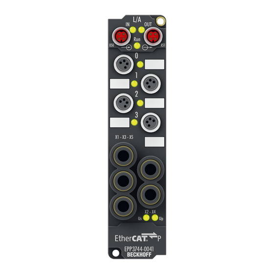
Product overview Product overview Introduction Tx+ / GND EtherCAT P EtherCAT P Rx+ / GND Rx- / U input downstream connection X01, X02 +24 V U Tx- / U Input Input Digital inputs, digital outputs X03, X04 +24 V U Output Input Pressure inputs,... -
Page 10: Technical Data
Product overview Technical data All values are typical values over the entire temperature range, unless stated otherwise. EtherCAT P Connection 2 x M8 socket, 4-pin, P-coded, red Distributed Clocks Minimum cycle time 700 µs Supply voltages Connection See EtherCAT P connection nominal voltage 24 V (-15 % / +20 %) sum current: I max. - Page 11 Product overview Digital inputs Number Connection 4 x M8 socket Characteristics EN 61131-2 type 3, compatible with type 1 Signal voltage "0" -3 … +5 V Signal voltage "1" +11 … +30 V Input current 3 mA at 24 V Sensor power supply 24 V from the control voltage U max. 0.5 A in total, short-circuit proof Digital outputs Number Connection...
-
Page 12: Absolute Pressure Measuring Range
Product overview 3.2.1 Absolute pressure measuring range The absolute pressure measuring range must be adhered to for each pressure connection, regardless of the chosen measurement method (absolute pressure / differential pressure): Absolute pressure 8 bar 7 bar Absolute pressure 6 bar 5 bar 2 bar Measuring... -
Page 13: Scope Of Supply
Product overview Scope of supply Make sure that the following components are included in the scope of delivery: • 1x EtherCAT P Box EPP3744-x041 • 2x protective cap for EtherCAT P socket, M8, red (pre-assembled) • 10x labels, blank (1 strip of 10) Pre-assembled protective caps do not ensure IP67 protection Protective caps are pre-assembled at the factory to protect connectors during transport. -
Page 14: Process Image
Product overview Process image The 6 digital inputs of the module can be found under DIG Inputs 1 to 6. • Input 1 - socket X01, pin 4 • Input 2 - socket X01, pin 2 • Input 3 - socket X02, pin 4 •... - Page 15 Product overview These are standard EtherCAT variables; more information in the general EtherCAT manual. EPP3744-x041 Version: 1.3...
-
Page 16: Mounting And Connection
Mounting and connection Mounting and connection Mounting 4.1.1 Dimensions 26.5 Ø 3.5 13.5 All dimensions are given in millimeters. The drawing is not true to scale. Housing features Housing material PA6 (polyamide) Sealing compound polyurethane Mounting two mounting holes Ø 3.5 mm for M3 Metal parts brass, nickel-plated Contacts... -
Page 17: Fixing
Mount the module with two M3 screws on the mounting holes in the corners of the module. The mounting holes have no thread. 4.1.3 Tightening torques for connectors Screw M8 connectors tight with a torque wrench. (e.g. ZB8801 from Beckhoff) Torque: 0.4 Nm. 4.1.4 Functional earth (FE) The upper mounting holes also serves as a connection for functional earth (FE). -
Page 18: Connection
Mounting and connection Connection 4.2.1 EtherCAT P WARNING Power supply from SELV/PELV power supply unit! SELV/PELV circuits (Safety Extra Low Voltage, Protective Extra Low Voltage) according to IEC 61010-2-201 must be used to supply the EtherCAT P Power Sourcing Device (PSD). Notes: • SELV/PELV circuits may give rise to further requirements from standards such as IEC 60204-1 et al, for example with regard to cable spacing and insulation. - Page 19 Core color Tx + yellow Rx + white Rx - : peripheral voltage, +24 V blue Tx - : control voltage, +24 V orange Housing Shield Shield Shield The core colors apply to EtherCAT P cables and ECP cables from Beckhoff. EPP3744-x041 Version: 1.3...
- Page 20 Mounting and connection 4.2.1.2 Status LEDs 4.2.1.2.1 Supply voltage EtherCAT P Box modules indicate the status of the supply voltages via two status LEDs. The status LEDs are labeled with the designations of the supply voltages: Us and Up. Display Meaning not present. green illuminated present.
- Page 21 Mounting and connection 4.2.1.3 Conductor losses Take into account the voltage drop on the supply line when planning a system. Avoid the voltage drop being so high that the supply voltage at the box lies below the minimum nominal voltage. Variations in the voltage of the power supply unit must also be taken into account.
-
Page 22: Pressure Inputs
Mounting and connection 4.2.2 Pressure inputs CAUTION Compressed air • Before connecting or disconnecting the module, check if the system is under pressure. ð The compressed air connections must not be opened while the system is under pressure. • The general safety and installation instructions for handling compressed air must be observed. X11 / Channel 1 X12 / Channel 2 X13 / Channel 3... - Page 23 Mounting and connection 2. Ensure that the hose is free of oil and grease. 3. Ensure that the end of the hose is free of scratches. 4. Optional: place a mark 14 mm from the end of the hose. This allows you to check whether the hose has been fully inserted after connection. 5.
-
Page 24: Digital Inputs And Outputs
Mounting and connection 4.2.3 Digital inputs and outputs Digital inputs/outputs M8, 4-pin EPP3744-x041 has four 4-pin M8 sockets. Sockets X01 and X02 each have two digital inputs, sockets X03 and X04 have one input and one output. The signals are connected via M8 connectors Sockets X01 and X02 Sockets X03 and X04 The sensors are supplied with a common maximum current of 0.5 A from the control voltage U... -
Page 25: Ul Requirements
Mounting and connection UL Requirements The installation of the EtherCAT Box Modules certified by UL has to meet the following requirements. Supply voltage CAUTION CAUTION! This UL requirements are valid for all supply voltages of all marked EtherCAT Box Modules! For the compliance of the UL requirements the EtherCAT Box Modules should only be supplied •... -
Page 26: Disposal
Mounting and connection Disposal Products marked with a crossed-out wheeled bin shall not be discarded with the normal waste stream. The device is considered as waste electrical and electronic equipment. The national regulations for the disposal of waste electrical and electronic equipment must be observed. Version: 1.3 EPP3744-x041... -
Page 27: Commissioning/Configuration
Commissioning/Configuration Commissioning/Configuration Absolute pressure / differential pressure NOTE Differential pressure measurement: Also observe the absolute pressure measuring range • Even in the case of differential pressure measurement, the absolute pressure measuring range must not be exceeded at any pressure input. See Technical data. You can set the pressure measurement method individually for each pressure connection: •... -
Page 28: Filter
Commissioning/Configuration Filter FIR and IIR filter The box is equipped with a digital filter which, depending on its settings, can adopt the characteristics of a Finite Impulse Response filter (FIR filter), or an Infinite Impulse Response filter (IIR filter). The filter can also be deactivated. - Page 29 Commissioning/Configuration Filter data FIR filter (8-channel boxes) Filter Attenuation Limit frequency (-3 dB) 50 Hz FIR > 50 dB 23 Hz 60 Hz FIR > 50 dB 27 Hz IIR filter The filter with IIR characteristics is a discrete time, linear, time invariant filter that can be set to eight levels (level 1 = weak recursive filter, up to level 8 = strong recursive filter).
-
Page 30: Limit Value Monitoring
Commissioning/Configuration Limit value monitoring Limit 1 and Limit 2, Index 0x80n0:13 [} 40], Index 0x80n0:14 [} 40] If the limits of the values that can be entered in indices 0x80n0:13 [} 40] and 0x80n0:14 [} 40] are violated, the bits in indices 0x60n0:03 [} 51] and 0x60n0:05 [} 51] are set accordingly (see sample below). The indices 0x80n0:07 [} 40] or 0x80n0:08 [} 40] serve to activate the limit value monitoring. - Page 31 Commissioning/Configuration Entry in Index 0x80n0:13 [} 40] (Limit 1): (2.8 V / 10 V) x 2 / 2 - 1 = 9,174 Entry in Index 0x80n0:14 [} 40] (Limit 2): (7.4 V / 10 V) x 2 / 2 - 1 = 24,247 Output: Input channel 1 Index 0x6000:03 [} 51] Index 0x6000:05 [} 51] 1.8 V 0x01...
-
Page 32: Restore The Delivery State
Commissioning/Configuration Restore the delivery state You can restore the delivery state of the backup objects as follows: 1. Ensure that TwinCAT is running in Config mode. 2. In CoE object 1011:0 "Restore default parameters" select parameter 1011:01 "Subindex 001". 3. Double-click on "Subindex 001". ð... -
Page 33: Coe Parameters
EtherCAT XML Device Description The display matches that of the CoE objects from the EtherCAT XML Device Description. We rec- ommend downloading the latest XML file from the download area of the Beckhoff website and in- stalling it according to installation instructions. - Page 34 CoE parameters Index (hex) Name Flags Default value Subindex AI TxPDO-Map Inputs Ch.2 0x09 (9 1A02 [} 45]:0 0x1A02:01 SubIndex 001 0x6030:01, 1 0x1A02:02 SubIndex 002 0x6030:02, 1 0x1A02:03 SubIndex 003 0x6030:03, 2 0x1A02:04 SubIndex 004 0x6030:05, 2 0x1A02:05 SubIndex 005 0x6030:07, 1 0x1A02:06 SubIndex 006...
- Page 35 CoE parameters Index (hex) Name Flags Default value Subindex SM output parameter 0x20 (32 1C32 [} 48]:0 0x1C32:01 Sync mode 0x0001 (1 0x1C32:02 Cycle time 0x003D0900 (4000000 0x1C32:03 Shift time 0x00000384 (900 0x1C32:04 Sync modes supported 0xC007 (49159 0x1C32:05 Minimum cycle time 0x000F4240 (1000000 0x1C32:06 Calc and copy time...
- Page 36 CoE parameters Index (hex) Name Flags Default value Subindex AI Inputs Ch.3 0x11 (17 6040 [} 50]:0 0x6040:01 Underrange 0x00 (0 0x6040:02 Overrange 0x00 (0 0x6040:03 Limit 1 0x00 (0 0x6040:05 Limit 2 0x00 (0 0x6040:07 Error 0x00 (0 0x6040:0F TxPDO State 0x00 (0 0x6040:10 TxPDO Toggle...
- Page 37 CoE parameters Index (hex) Name Flags Default value Subindex AI Settings Ch.2 0x19 (25 8030 [} 41]:0 0x8030:01 Enable user scale 0x00 (0 0x8030:06 Enable filter 0x01 (1 0x8030:07 Enable limit 1 0x00 (0 0x8030:08 Enable limit 2 0x00 (0 0x8030:0A Enable user calibration 0x00 (0 0x8030:0B...
- Page 38 CoE parameters Index (hex) Name Flags Default value Subindex AI Settings Ch.4 0x19 (25 8050 [} 43]:0 0x8050:01 Enable user scale 0x00 (0 0x8050:06 Enable filter 0x01 (1 0x8050:07 Enable limit 1 0x00 (0 0x8050:08 Enable limit 2 0x00 (0 0x8050:0A Enable user calibration 0x00 (0 0x8050:0B...
-
Page 39: Object Description And Parameterization
EtherCAT XML Device Description The display matches that of the CoE objects from the EtherCAT XML Device Description. We rec- ommend downloading the latest XML file from the download area of the Beckhoff website and in- stalling it according to installation instructions. - Page 40 CoE parameters Index 8011 Safe state value Index (hex) Name Meaning Data type Flags Default 8011:0 Safe state value UINT8 0x02 (2 8011:01 Output 1 Output -> 0 in case of Safe State condition BOOLEAN 0x00 (0 Output -> 1 in case of Safe State condition 8011:02 Output 2 Output ->...
- Page 41 CoE parameters Index 8030 AI settings Ch.2 (parameterization of channel 2) Index (hex) Name Meaning Data type Flags Default 8030:0 AI Settings Ch.2 Maximum subindex UINT8 0x19 (25 8030:01 Enable user scale User scale is active. BOOLEAN 0x00 (0 8030:06 Enable filter Enable filter, which makes PLC-cycle-synchronous BOOLEAN...
- Page 42 CoE parameters Index 8040 AI settings Ch.3 (parameterization of channel 3) Index (hex) Name Meaning Data type Flags Default 8040:0 AI Settings Ch.3 Maximum subindex UINT8 0x19 (25 8040:01 Enable user scale User scale is active. BOOLEAN 0x00 (0 8040:06 Enable filter Enable filter, which makes PLC-cycle-synchronous BOOLEAN...
-
Page 43: Standard Objects (0X1000-0X1Fff)
CoE parameters Index 8050 AI Settings Ch.3 (parameterization of channel 4) Index (hex) Name Meaning Data type Flags Default 8050:0 AI Settings Ch.4 Maximum subindex UINT8 0x19 (25 8050:01 Enable user scale User scale is active. BOOLEAN 0x00 (0 8050:06 Enable filter Enable filter, which makes PLC-cycle-synchronous BOOLEAN... - Page 44 CoE parameters Index 1009: Hardware version Index (hex) Name Meaning Data type Flags Default 1009:0 Hardware version Hardware version of the EtherCAT slaves STRING Index 100A Software version Index (hex) Name Meaning Data type Flags Default 100A:0 Software version Firmware version of the EtherCAT slaves STRING Index 1018 Identity Index (hex) Name...
- Page 45 CoE parameters Index 1A00 DIG TxPDO-Map Inputs Index (hex) Name Meaning Data type Flags Default 1A00:0 DIG TxPDO-Map In- PDO Mapping TxPDO 1 UINT8 0x07 (7 puts 1A00:01 SubIndex 001 1. PDO Mapping entry (object 0x6000 (Dig Inputs), entry UINT32 0x6000:01, 1 0x01 (Input 1)) 1A00:02...
- Page 46 CoE parameters Index 1A03 AI TxPDO-Map Inputs Ch.3 Index (hex) Name Meaning Data type Flags Default 1A03:0 AI TxPDO-Map Inputs PDO Mapping TxPDO 4 UINT8 0x09 (9 Ch.3 1A03:01 SubIndex 001 1. PDO Mapping entry (object 0x6040 (AI Inputs Ch.3), UINT32 0x6040:01, 1 entry 0x01 (Underrange))
- Page 47 CoE parameters Index 1C00 Sync manager type Index (hex) Name Meaning Data type Flags Default 1C00:0 Sync manager type Usage of the Sync Manager channels UINT8 0x04 (4 1C00:01 SubIndex 001 Sync-Manager Type Channel 1: Mailbox Write UINT8 0x01 (1 1C00:02 SubIndex 002 Sync-Manager Type Channel 2: Mailbox Read...
- Page 48 CoE parameters Index 1C32 SM output parameter Index (hex) Name Meaning Data type Flags Default 1C32:0 SM output parameter Synchronization parameter of the outputs UINT8 0x20 (32 1C32:01 Sync mode actual synchronization mode: UINT16 0x0001 (1 • 0: Free Run •...
- Page 49 CoE parameters Index 1C33 SM input parameter Index (hex) Name Meaning Data type Flags Default 1C33:0 SM input parameter Synchronization parameter of the inputs UINT8 0x20 (32 1C33:01 Sync mode actual synchronization mode: UINT16 0x0022 (34 • 0: Free Run •...
-
Page 50: Profile Specific Objects (0X6000-0Xffff)
CoE parameters 6.2.3 Profile specific objects (0x6000-0xFFFF) Profile specific objects (0x6000-0xFFFF) The profile specific objects have the same meaning for all EtherCAT Slaves which support the profile 5001. Index 6020 AI Inputs Ch.1 Index (hex) Name Meaning Data type Flags Default 6020:0 AI Inputs Ch.1... - Page 51 CoE parameters Index 6050 AI Inputs Ch.4 Index (hex) Name Meaning Data type Flags Default 6050:0 AI Inputs Ch.4 UINT8 0x11 (17 6050:01 Underrange Underrange event active BOOLEAN 0x00 (0 6050:02 Overrange Overrange event active BOOLEAN 0x00 (0 6050:03 Limit 1 BIT2 0x00 (0 6050:05...
- Page 52 CoE parameters Index 803F AI Vendor data Ch.2 Index (hex) Name Meaning Data type Flags Default 803F:0 AI Vendor data Ch.2 UINT8 0x04 (4 803F:01 Calibration offset INT32 0x00000000 pressure 803F:02 Calibration gain pres- INT16 0x4000 sure (16384 803F:03 Calibration offset INT32 0x00000000 temp...
- Page 53 CoE parameters Index F010 Module list Index (hex) Name Meaning Data type Flags Default F010:0 Module list UINT8 0x06 (6 F010:01 SubIndex 001 UINT32 0x00000118 (280 F010:02 SubIndex 002 UINT32 0x00000118 (280 F010:03 SubIndex 003 UINT32 0x0000012C (300 F010:04 SubIndex 004 UINT32 0x0000012C (300...
- Page 54 CoE parameters Index F80F AI Vendor data Reference Index (hex) Name Meaning Data type Flags Default F80F:0 AI Vendor data Refer- UINT8 0x04 (4 ence F80F:01 Calibration offset INT32 0x00000000 pressure F80F:02 Calibration gain pres- INT16 0x4000 sure (16384 F80F:03 Calibration offset INT32 0x00000000...
-
Page 55: Appendix
Appendix Appendix General operating conditions Protection degrees (IP-Code) The standard IEC 60529 (DIN EN 60529) defines the degrees of protection in different classes. 1. Number: dust protection and Definition touch guard Non-protected Protected against access to hazardous parts with the back of a hand. Protected against solid foreign objects of Ø 50 mm Protected against access to hazardous parts with a finger. -
Page 56: Accessories
ZB8801-0000 Torque wrench for plugs, 0.4…1.0 Nm ZB8801-0001 Torque cable key for M8 / wrench size 9 for ZB8801-0000 Further accessories Further accessories can be found in the price list for fieldbus components from Beckhoff and online at https://www.beckhoff.com. Version: 1.3 EPP3744-x041... -
Page 57: Version Identification Of Ethercat Devices
Associated and synonymous with each revision there is usually a description (ESI, EtherCAT Slave Information) in the form of an XML file, which is available for download from the Beckhoff web site. From 2014/01 the revision is shown on the outside of the IP20 terminals, see Fig. “EL5021 EL terminal, standard IP20 IO device with batch number and revision ID (since 2014/01)”. -
Page 58: Version Identification Of Ep/Epi/Epp/Er/Eri Boxes
Version identification of EP/EPI/EPP/ER/ERI boxes The serial number/ data code for Beckhoff IO devices is usually the 8-digit number printed on the device or on a sticker. The serial number indicates the configuration in delivery state and therefore refers to a whole production batch, without distinguishing the individual modules of a batch. -
Page 59: Beckhoff Identification Code (Bic)
7.3.3 Beckhoff Identification Code (BIC) The Beckhoff Identification Code (BIC) is increasingly being applied to Beckhoff products to uniquely identify the product. The BIC is represented as a Data Matrix Code (DMC, code scheme ECC200), the content is based on the ANSI standard MH10.8.2-2016. - Page 60 Fig. 10: Example DMC 1P072222SBTNk4p562d71KEL1809 Q1 51S678294 An important component of the BIC is the Beckhoff Traceability Number (BTN, position 2). The BTN is a unique serial number consisting of eight characters that will replace all other serial number systems at Beckhoff in the long term (e.g.
-
Page 61: Electronic Access To The Bic (Ebic)
Electronic access to the BIC (eBIC) Electronic BIC (eBIC) The Beckhoff Identification Code (BIC) is applied to the outside of Beckhoff products in a visible place. If possible, it should also be electronically readable. Decisive for the electronic readout is the interface via which the product can be electronically addressed. - Page 62 Appendix ◦ The device must be in PREOP/SAFEOP/OP for access: ◦ the object 0x10E2 will be introduced into stock products in the course of a necessary firmware revision. ◦ From TwinCAT 3.1. build 4024.24 the functions FB_EcCoEReadBIC and FB_EcCoEReadBTN for reading into the PLC and further eBIC auxiliary functions are available in the Tc2_EtherCAT Library from v3.3.19.0.
-
Page 63: Support And Service
Please contact your Beckhoff branch office or representative for local support and service on Beckhoff products! The addresses of Beckhoff's branch offices and representatives round the world can be found on her internet pages: https://www.beckhoff.com You will also find further documentation for Beckhoff components there. - Page 65 Beckhoff Automation GmbH & Co. KG Hülshorstweg 20 33415 Verl Germany Phone: +49 5246 9630 info@beckhoff.com www.beckhoff.com...
Need help?
Do you have a question about the EPP3744 041 Series and is the answer not in the manual?
Questions and answers