Table of Contents
Advertisement
Quick Links
Advertisement
Table of Contents

Related Manuals for Advantech MIO-2363ALW-P1A1


Summary of Contents for Advantech MIO-2363ALW-P1A1
- Page 1 User Manual MIO-2363 ® Intel Atom™ x6000E Series 2.5" PICO-ITX SBC...
- Page 2 No part of this manual may be reproduced, copied, translated, or transmitted in any form or by any means without the prior written permission of Advantech Co., Ltd. The information provided in this manual is intended to be accurate and reliable.
- Page 3 Product Warranty (2 Years) Advantech warrants the original purchaser that each of its products will be free from defects in materials and workmanship for two years from the date of purchase. This warranty does not apply to any products that have been repaired or altered by persons other than repair personnel authorized by Advantech, or products that have been subject to misuse, abuse, accident, or improper installation.
- Page 4 This product has passed the CE test for environmental specifications when shielded cables are used for external wiring. We recommend the use of shielded cables. This type of cable is available from Advantech. Please contact your local supplier for ordering information.
- Page 5 Packing List Before system installation, check that the items listed below are included and in good condition. If any item does not accord with the list, contact your dealer immediately. 1 x MIO-2363 SBC 1 x USB cable 20cm (p/n: 1700030406-01) ...
- Page 6 MIO-2363 User Manual...
-
Page 7: Table Of Contents
Contents Chapter Introduction..........1 Introduction ....................2 Specifications .................... 2 Block Diagram................... 4 Chapter Mechanical Specifications....5 Introduction ....................6 Board Layout: Dimensions ................ 6 Figure 2.1 MIO-2363 Mechanical Diagram (Top Side) ....6 Figure 2.2 MIO-2363 Mechanical Diagram (Bottom Side) ... 6 Figure 2.3 MIO-2363 Mechanical Diagram (Coastline) .... - Page 8 Appendix A System I/O Ports ....... 65 System I/O Ports..................66 DMA Channel Assignments ..............66 1st MB Memory Map................67 Interrupt Assignments ................67 MIO-2363 User Manual viii...
- Page 9 Chapter Introduction...
-
Page 10: Chapter 1 Introduction
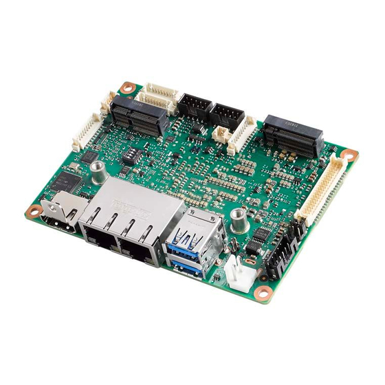
Introduction Advantech MIO-2363 is a 2.5″ PICO-ITX form factor SBC (compact series, 100 x 72 ® ® mm; 3.9 x 2.8 in), powered by an Intel Atom x6000E series processor. It provides embedded iManager 3.0, SUSI 4.0, and Advantech’s WISE-DeviceOn to monitor and control system operation effectively and remotely. - Page 11 SATA USB 2.0 Serial Bus 1x I2C COM Port 2 x RS-232/422/485 GPIO 8-bit general purpose input output I/O Internal I/O Audio Realtek ALC888, Line-in/Line-out/MIC Inverter 3.3V/5V/12V LPC/SPI Bus eSPI for EIO-211/ SPI for TPM/no LPC Front Panel Power-on, Reset, Buzzer, SATA LED, CaseOpen Control Watchdog Timer Programmable 1 ~ 65535 sec/min...
-
Page 12: Block Diagram
Line-in/out/MIC Intel Elkhart Lake 2 x USB 2.0 Atom x6000E Series eMMC 64/128GB M.2 E-Key PCIe, USB2.0 2230 SATA, USB2.0 256M BIOS M.2 B-Key PCIEx1 2242 eSPI Advantech EIO-211 COM1 COM2 Watchdog GPIO 8b RS-232/422/485 RS-232/422/485 Multi-stage MIO-2363 User Manual... -
Page 13: Chapter 2 Mechanical Specifications
Chapter Mechanical Specifications... -
Page 14: Introduction
Introduction The MI/O compact form factor SBC is a new-generation SBC designed with a variety of mechanical improvements. This chapter includes board dimensions and assembly instructions for the standard thermal solution. Board Layout: Dimensions Figure 2.1 MIO-2363 Mechanical Diagram (Top Side) Figure 2.2 MIO-2363 Mechanical Diagram (Bottom Side) MIO-2363 User Manual... - Page 15 Figure 2.3 MIO-2363 Mechanical Diagram (Coastline) Figure 2.4 MIO-2363 Mechanical Diagram (with Heatsink) MIO-2363 User Manual...
-
Page 16: Quick Installation Guide
Quick Installation Guide This section introduces installation of the heatsink, which is contained in the white box inside the package. Please assemble it as in the following diagram. Remember to remove the plastic from the thermal pad before assembling. 2.3.1 Heatsink Figure 2.5 MIO-2363 Heatsink Installation Figure 2.6 MIO-2363 Heatsink Installation... -
Page 17: Chapter 3 Installation
Chapter Installation... -
Page 18: Jumpers & Switches
Jumpers & Switches Table 3.1: Jumpers and Switches VDD1 Panel Voltage Selection Jumper Miscellaneous Switch Connectors Table 3.2: Connectors Label Function C Internal Connector Front Panel Internal Connector DC Power Input Connector COM1 COM Port Internal Connector 1 COM2 COM Port Internal Connector 2 USB1 USB 3.2 Connector USB2... -
Page 19: Locating Connectors
Locating Connectors Figure 3.1 MIO-2363 Connector Locations (Bottom Side) Setting Jumpers You may configure your card to match the needs of your application by setting jump- ers. A jumper is a metal bridge used to close an electric circuit. It consists of two metal pins and a small metal clip (often protected by a plastic cover) that slides over the pins to connect them. -
Page 20: Miscellaneous Switch (Sw1)
3.4.1 Miscellaneous Switch (SW1) Part Number 1600000084 Description SLIDE SW CHS-04TA (29) SMD 8P 6.6x5.4x2.4mm Setting Function ON: AT mode (default) OFF: ATX mode Reserved OFF: Normal (default) ON: Load BIOS (default) ON: Top Swap Override ENABLE OFF: Top Swap Override DISABLE 3.4.2 Panel Voltage Selection (VDD1) Part Number... -
Page 21: Dc Power Input Connector (Cn7)
3.4.3 DC Power Input Connector (CN7) Part Number 1655003962 Description WAFER 2P 3.96mm 180D(M) DIP A3963WV2-2P Signal Pin Definition +V24_V12_DC_IN 3.4.4 Audio Internal Connector: AUDIO1 Part Number 1653008214-01 Description BH 2x5P/2.0/PA6T/G-FL/VA(M)/S/BK/H6.05/C+R Signal Pin Definition LOUTR LINR LOUTL LINL FRONT-JD MIC1R MIC1L MIO-2363 User Manual... -
Page 22: Usb 2.0 Internal Connector: Usb2
3.4.5 USB 2.0 Internal Connector: USB2 Part Number 1653008214-01 Description BH 2x5P/2.0/PA6T/G-FL/VA(M)/S/BK/H6.05/C+R Signal Pin Definition +USBV3 +USBV3 USB2_D6- USB2_D5- USB2_D6+ USB2_D5+ 3.4.6 LVDS Connector (LVDS1) MIO-2363 User Manual... - Page 23 Part Number 1653008443-01 Description Wafer 2x20P/1.25/PA9T/VA(M)/GFL/S/WH/H4.8/W P Signal Pin Definition +V_LCD +V_LCD +V_LCD +V_LCD LVDS1_0_D0- LVDS1_1_D0- LVDS1_0_D0+ LVDS1_1_D0+ LVDS1_0_D1- LVDS1_1_D1- LVDS1_0_D1+ LVDS1_1_D1+ LVDS1_0_D2- LVDS1_1_D2- LVDS1_0_D2+ LVDS1_1_D2+ LVDS1_0_CLK- LVDS1_1_CLK- LVDS1_0_CLK+ LVDS1_1_CLK+ LVDS0_DDCCLK_AUX+ LVDS0_DDCCLK_AUX- LVDS1_0_D3- LVDS1_1_D3- LVDS1_0_D3+ LVDS1_1_D3+ LVDS1_VCON MIO-2363 User Manual...
-
Page 24: Panel Inverter Connector (Bl1)
3.4.7 Panel Inverter Connector (BL1) Part Number 1653007905-01 Description Wafer 1X5P/2.0mm/VA/Sn/BK/S/H6.5/C+R Signal Pin Definition +V12_1_INVERTER_0 LVDS1_z_ENABKL EC_LVDS1_z_PWM +V5_1_INVERTER_0 3.4.8 COM Port Internal Connector 1 (COM1) Part Number 1653007728-01 Description Wafer 1x10P/1.25mm/PA/M/VA/WH/Sn/H4.7mm/WO CAP Signal Pin Definition COM1_RI# COM1_DTR# COM1_CTS# COM1_TXD COM1_RTS# COM1_RXD COM1_DSR# COM1_DCD#... -
Page 25: Com Port Internal Connector 2 (Com2)
3.4.9 COM Port Internal Connector 2 (COM2) Part Number 1653007728-01 Description Wafer 1x10P/1.25mm/PA/M/VA/WH/Sn/H4.7mm/WO CAP Signal Pin Definition COM2_RI# COM2_DTR# COM2_CTS# COM2_TXD COM2_RTS# COM2_RXD COM2_DSR# COM2_DCD# 3.4.10 GPIO Internal Connector (GPIO1) Part Number 1653007728-01 Description Wafer1x10P/1.25mm/PA/M/VA/WH/Sn/H4.7mm/WO CAP Signal Pin Definition EC_P1_GPIO7 EC_P1_GPIO2 EC_P1_GPIO6 EC_P1_GPIO1... -
Page 26: I2C Internal Connector (Cn1)
3.4.11 I2C Internal Connector (CN1) Part Number 1655904020 Description WAFER 4P 1.25mm 180D(M) SMD 85205-04001 Signal Pin Definition EC_I2C0_z_DAT EC_I2C0_z_CLK +V5_I2CCONN 3.4.12 Front Panel Internal Connector (CN5) Part Number 1653007728-01 Description cWafer 1x10P/1.25mm/PA/M/VA/WH/Sn/H4.7mm/WO CAP Signal Pin Definition BUZZER- BUZZER+ RDC_CASEOPEN FP_HDD_a_LED# FP_a_PSIN# FP_a_RST#... -
Page 27: E-Key Connector (M2_1)
3.4.13 M.2 E-Key Connector (M2_1) Part Number 1654012663-01 Description NGFF 75P/0.5mm/(F)/LCP/RA/GFL/S/BK/H8.5mm/E-k Signal Pin Definition +V3.3SB_M.2_E USB2_z_P9+ +V3.3SB_M.2_E USB2_z_P9- M2E1_PCIE_TX+ M2E1_PCIE_TX- PCIE4_RX+ PCIE4_RX- MIO-2363 User Manual... - Page 28 CLK_M2E_z_PCIE+ CLK_M2E_z_PCIE- M2E1_SUSCLK PLTRST_BUF# PCIE_a_CLKREQ# BT_DISABLE# PCIE_WAKE# WIFI_DISABLE# +V3.3SB_M.2_E +V3.3SB_M.2_E MIO-2363 User Manual...
-
Page 29: B-Key Connector (M2_2)
3.4.14 M.2 B-Key Connector (M2_2) Part Number 1654012087-02 Description NGFF 75P/0.5mm/(F)/LCP/RA/GFL/S/BK/H8.50/B-key Signal Pin Definition +3.3V +V3.3SB_M.2_B +V3.3SB_M.2_B +V1.8_DUAL USB2_a_P4+ +V3.3SB_M.2_B USB2_a_P4- +V3.3SB +V1.8_DUAL SATA_PCIE_C_RX+ SATA_PCIE_C_RX- MIO-2363 User Manual... - Page 30 SATA_PCIE_C_TX- SATA_PCIE_C_TX+ PLTRST_BUF#_M2B1 PCIE_a_CLKREQ2# CLK100M_M2B1_R_D2- PCIE_WAKE#_M2B1 CLK100M_M2B1_R_D2+ M2B1_RESET#_R M2B1_SUSCLK +V3.3SB +V3.3SB_M.2_B +V3.3SB_M.2_B +V3.3SB_M.2_B +V3.3SB MIO-2363 User Manual...
-
Page 31: Rtc Battery Connector (Bat1)
3.4.15 RTC Battery Connector (BAT1) Part Number 1655902000 Description WAFER 2P 1.25mm 180D(M) SMD 85205-02001 Signal Pin Definition +VBAT_R MIO-2363 User Manual... - Page 32 MIO-2363 User Manual...
-
Page 33: Chapter 4 Ami Bios Setup
Chapter AMI BIOS Setup... -
Page 34: Entering Setup
BIOS supports your CPU. If there is no number assigned to the patch code, please contact an Advantech application engineer to obtain an up-to-date patch code file. This will ensure that your CPU‘s system status is valid. -
Page 35: Advanced Bios Features Setup
The Main BIOS setup screen has two main frames. The left frame displays all the options that can be configured. Grayed-out options cannot be configured; options in blue can. The right frame displays the key legend. Above the key legend is an area reserved for a text message. When an option is selected in the left frame, it is highlighted in white. - Page 36 4.1.1.1 RC ACPI Settings Native PCIE Enable Enable/Disable PCIE Native Control reported in ACPI Table. Native ASPM Choose ASPM feature is controlled by OS or BIOS. MIO-2363 User Manual...
- Page 37 4.1.1.2 CPU Configuration CPU Flex Ratio Override Enable/Disable CPU Flex Ratio Programming. Hardware Prefetcher This item allows users to enable or disable the hardware prefetcher feature. Adjacent Cache Line Prefetch This item allows users to enable or disable the adjacent cache line prefetch fea- ture.
- Page 38 4.1.1.3 Power & Performance CPU – Power Management Control CPU – Power Management Control Options. GT – Power Management Control GT – Power Management Control Options. MIO-2363 User Manual...
- Page 39 Power Management Control Boot Performance mode Select the performance state that the BIOS will set before OS handoff. ® Intel SpeedStep™ Allows more than two frequency ranges to be supported. Race to Halt (RTH) Enable/Disable Race to Halt feature. RTH will dynamically increase CPU fre- quency in order to enter pkg C-State faster to reduce overall power.
- Page 40 View/Configure Turbo Options Energy Efficient P-state Enable/Disable Energy Efficient P-state feature. Package Power Limit MSR Lock Enable/Disable locking of Package Power Limit 1 settings. Power Limit 1 Override Enable/Disable Power Limit 1 override. Power Limit 2 Override ...
- Page 41 Power Limit 3 Settings Power Limit 3 Override Enable/Disable Power Limit 3 override. MIO-2363 User Manual...
- Page 42 GT - Power Management Control RC6 (Render Standby) Check to enable render standby support. Maximum GT frequency Maximum GT frequency limited by user. Disable Turbo GT frequency Enable/Disable Turbo GT frequency. MIO-2363 User Manual...
- Page 43 4.1.1.4 PCH-FW Configuration ME State When disabled ME will be put ME into temporarily disabled mode. ME Unconfig on RTC Clear When disabled, ME will not be unconfigured on RTC Clear. Core BIOS Done Message Enable/Disable Core BIOS done message sent to ME. Firmware Update Configuration ...
- Page 44 4.1.1.5 ACPI Settings Enable ACPI Auto Configuration Enable or disable BIOS ACPI auto configuration. Enable Hibernation Enables or disables system ability to Hibernate (OS/S4 Sleep State). This option may be not effective with some OS. ACPI Sleep State ...
- Page 45 4.1.1.6 iManager Configuration CPU Shutdown Temperature Enable/Disable CPU Shutdown Temperature. Power Saving Mode Enable/Disable power saving mode. Backlight Enable Polarity Switch Backlight Enable Polarity for Native or Invert. Backlight Control Mode Switch Backlight Control to PWM or DC mode. Brightness PWM Polarity ...
- Page 46 Serial Port 1 Configuration Serial Port Enable or disable Serial Port (COM). Change Settings Select an optimal settings for Super IO device. COM Port Mode COM Port Mode selection. MIO-2363 User Manual...
- Page 47 Serial Port 2 Configuration Serial Port Enable or disable Serial Port (COM). Change Settings Select an optimal settings for Super IO device. COM Port Mode COM Port Mode selection. MIO-2363 User Manual...
- Page 48 Hardware Monitor Watch Dog Timer Configuration Watch Dog Timer Enable or disable watch dog timer function. MIO-2363 User Manual...
- Page 49 GPIO Configuration GPIO Control Enable Choose to control GPIO by EC or user override during POST stage. GPIO0/1/2/3/4/5/6/7 Configure GPIO0/1/2/3/4/5/6/7. MIO-2363 User Manual...
- Page 50 ACPI Report Method Configuration ACPI Report Method Control Select ACPI reporting method for EC Devices. Active High-Speed COM Port Select to Enable High-Speed COM Port or Standard COM Port. ACPI Report Method for I2C Bus Select ACPI reporting method for EC I2C Bus. ACPI Report Method for SMBus ...
- Page 51 4.1.1.7 NCT6126D HW Monitor Smart Fan Function Enable or disable Smart Fan. Smart Fan Function Enable or disable Smart Fan. Digital I/O Configuration Configure the digital I/O pins. ACPI CPU Shutdown Temperature Select the critical temperature value that OSPM must shutdown the system. Case Open Detection ...
- Page 52 4.1.1.8 Trusted Computing Security Device Support Enable or disable BIOS support for security device. SHA-1 PCR Bank Enable or disable SHA-1 PCR Bank. SHA256 PCR Bank Enable or disable SHA256 PCR Bank. SHA384 PCR Bank Enable or disable SHA384 PCR Bank. Pending operation ...
- Page 53 4.1.1.9 S5 RTC Wake Settings Wake system from S5 Enable or disable System wake on alarm event. Select FixedTime, system will wake on the hr:min:sec specified. MIO-2363 User Manual...
- Page 54 4.1.1.10 Serial Port Console Redirection Console Redirection This item allows users to enable or disable console redirection for Microsoft Windows Emergency Management Services (EMS). Console Redirection This item allows users to configuration console redirection detail settings. MIO-2363 User Manual...
- Page 55 4.1.1.11 USB Configuration Legacy USB Support Enables Legacy USB Support. AUTO option disables legacy support if no USB devices are connected. Disable option will keep USB devices available only for EFI applications. XHCI Hand-off This is a workaround for OS without XHCI hand-off support. The XHCI owner- ship change should be claimed by XHCI driver.
- Page 56 4.1.1.12 Network Stack Configuration Network Stack Enable/disable UEFI Network Stack. 4.1.1.13 NVMe Configuration MIO-2363 User Manual...
- Page 57 4.1.1.14 SDIO Configuration SDIO Access Mode Select SD Device access mode in Auto/DMA/PIO. MIO-2363 User Manual...
-
Page 58: Chipset Configuration
4.1.2 Chipset Configuration Select the Chipset tab from the MIO-2363 setup screen to enter the Chipset BIOS Setup screen. You can display a Chipset BIOS Setup option by highlighting it using the <Arrow> keys. All Plug and Play BIOS Setup options are described in this sec- tion. - Page 59 4.1.2.1 System Agent (SA) Configuration Memory Configuration Memory configuration parameters. Graphics Configuration Graphics configuration parameters. VT-d VT-D capability. X2APIC Opt Out Enable/Disable X2APIC opt out bit. IGD VTD Enable Enable/Disable IGD VTD. Above 4GB MMIO BIOS assignment ...
- Page 60 Memory Configuration Max TOLUD Maximum Value of TOLUD. SAGV System Agent Geyserville. Enable RH Prevention Actively prevent row hammer attacks. Power Down Mode CKE Power Down Mode control. Page Close Idle Timeout Page Close Idle Timeout Control. Memory Scrambler ...
- Page 61 Graphics Configuration Graphics Turbo IMON Current Graphics turbo IMON current values supported. GTT Size Select the GTT size. Aperture Size Select the aperture size. PSMI Support Enable/Disable PSMI. DVMT Pre-Allocated Select DVMT 5.0 Pre-Allocated (fixed) graphics memory size used by the inter- nal graphics device.
- Page 62 Boot Display Control NXP Non-EDID Support Non-EDID support. Color Depth & Data Packing Color depth and data packing format for Non-EDID support. Dual LVDS Mode Select LVDS bus to single bus mode or dual bus mode. LVDS Panel Type ...
- Page 63 4.1.2.2 PCH-IO Configuration PCI Express Configuration PCI Express configuration settings. SATA Configuration SATA device options settings. USB Configuration USB configuration settings. Security Configuration Security configuration settings. HD Audio Configuration HD Audio subsystem configuration settings. SCS Configuration ...
- Page 64 PCI Express Configuration DMI Link ASPM Control This item controls Active State Power Management of the DMI link. Port8xh Decode PCI Express Port8xh decode enable/disable. Peer Memory Write Enable Peer memory write enable/disable. PCH PCI Express Clock Gating ...
- Page 65 SATA Configuration SATA Controller(s) Enable/disable SATA device. SATA Mode Selection Determine how SATA controllers operate. Aggressive LPM Support Enabled PCH to aggressively enter link power state. SATA Controller Speed Indicates the maximum speed the SATA controller can support. MIO-2363 User Manual...
- Page 66 USB Configuration XHCI Compliance Mode Option to enable compliance mode. USB3 Link Speed Selection This option is to select USB3 Link Speed GEN1 or GEN2. USB PDO Programming Select “Enabled” if Port Disable Override functionality is used. USB Overcurrent ...
- Page 67 Security Configuration RTC Memory Lock Enable will lock bytes 38h-3Fh in the lower/upper 128-byte bank of RTC RAM. BIOS Lock Enable or disable the PCH BIOS Lock Enable feature. Force unlock on all GPIO pads If Enabled BIOS will force all GPIO pads to be in an unlock state. MIO-2363 User Manual...
- Page 68 HD Audio Configuration HD Audio Control detection of the HD-Audio device. Disabled = HDA will be uncondition- ally disabled. Enabled = HDA will be unconditionally Enabled. MIO-2363 User Manual...
- Page 69 SCS Configuration eMMC 5.1 Controller Enable or disable SCS eMMC 5.1 controller. eMMC 5.1 HS400 Mode Enable or disable SCS eMMC 5.1 HS400 mode. Enable HS400 software tuning Software tuning should improve eMMC HS400 stability at the expense of boot time.
-
Page 70: Security
4.1.3 Security Select Security Setup from the MIO-2363 Setup main BIOS setup menu. All Security Setup options, such as password protection and virus protection are described in this section. To access the sub menu for the following items, select the item and press <Enter>: Change Administrator/User Password ... -
Page 71: Boot
4.1.4 Boot Setup Prompt Timeout Number of seconds that the firmware will wait before initiating the original default boot selection. A value of 0 indicates that the default boot selection is to be initiated immediately on boot. A value of 65535 (0xFFFF) indicates that firm- ware will wait for user input before booting. -
Page 72: Save & Exit
4.1.5 Save & Exit Save Changes and Exit This item allows you to exit system setup after saving the changes. Discard Changes and Exit This item allows you to exit system setup without saving any changes. Save Changes and Reset ... -
Page 73: Appendix A System I/O Ports
Appendix System I/O Ports... -
Page 74: System I/O Ports
System I/O Ports Addr. Range (Hex) Device 00h-1Fh DMA Controller 20h-2Dh Interrupt Controller 2Eh–2Fh Motherboard resources 30h-3Dh Interrupt Controller 40h-43h Timer/Counter 4Eh–4Fh Motherboard resources 50h-53h Timer/Counter 60h-6Fh 8042 (keyboard controller)/NMI Controller/Microcontroller 70h-7Fh Real-time Controller 80h-8Fh Debug Port/Reserved 90h-9Fh Debug Port/Reset Generator A0h-ADh Interrupt Controller B0h-B1h Interrupt Controller B4h-BDh Power Management... -
Page 75: 1St Mb Memory Map
1st MB Memory Map Addr. Range (Hex) Device E0000h - FFFFFh System board D0000h - DFFFFh PCI Bus C0000h - CFFFFh System board A0000h - BFFFFh PCI Bus A0000h - BFFFFh Intel® HD Graphic 00000h - 9FFFFh System board Interrupt Assignments Interrupt# Interrupt source NMI Parity error detected IRQ0 System timer... - Page 76 No part of this publication may be reproduced in any form or by any means, such as electronically, by photocopying, recording, or otherwise, without prior written permission from the publisher. All brand and product names are trademarks or registered trademarks of their respective companies. © Advantech Co., Ltd. 2024...
Need help?
Do you have a question about the MIO-2363ALW-P1A1 and is the answer not in the manual?
Questions and answers