
Subscribe to Our Youtube Channel
Related Manuals for Wren Vogue 300 50/50


Summary of Contents for Wren Vogue 300 50/50
- Page 1 TOWER UNIT 300-600, 2 Door 6 Shelf Assembly Guide 300 50/50 500 50/50 600 50/50 500 70/30 600 70/30 300 70/30 For Internal Use: FI.WR.INS.040_WKIN00140_TOWER_300_600_2Dr6Shelf_Rev11...
- Page 2 TOWER UNIT 300-600, 2 Door 6 Shelf Assembly Guide BEFORE YOU START INSTALLATION SHOULD BE PERFORMED BY A COMPETENT PERSON ONLY. THIS PRODUCT COULD BE DANGEROUS IF INCORRECTLY INSTALLED NOT to be used with CAM LOCK Page 2 For Internal Use: FI.WR.INS.040_WKIN00140_TOWER_300_600_2Dr6Shelf_Rev11...
- Page 3 TOWER UNIT 300-600, 2 Door 6 Shelf Assembly Guide Frontal Panel A Panel B Panel C Panel D Frontal Shelf x2 End Panel (70/30 Option) x1 Back Panel x2 Fixed Shelf x2 Rail (50/50 Option) x6 Loose Shelf x2 Front Panel x2 Front Panel (Packed Separately) (Packed Separately)
- Page 4 TOWER UNIT 300-600, 2 Door 6 Shelf Assembly Guide (F) x16 (L) x32 (K) x10 (G) x12 (H) x12 Wooden 15mm 30mm Cam Lock Cam Dowel Dowel Screw Screw (Expanding) (M) x4 (U) x2 L Bracket (Z) x24 (N) x2 Fixing Plate Cover Cap Shelf Peg Metal...
- Page 5 TOWER UNIT 300-600, 2 Door 6 Shelf Assembly Guide Step 1. Seat dowels (F) into holes in both end panels (A) as shown. Step 2. Seat expanding cam dowels (G) into holes in both end panels (A) as shown. Page 5 For Internal Use: FI.WR.INS.040_WKIN00140_TOWER_300_600_2Dr6Shelf_Rev11...
- Page 6 TOWER UNIT 300-600, 2 Door 6 Shelf Assembly Guide Step 3. Attach panels (C) & (D) to end panels (A), using expanding cam dowels (G), and wooden dowels (F) in positions as shown. All cam lock (H) holes are to be positioned facing the outside of the unit carcase, for ease of tightening.
- Page 7 TOWER UNIT 300-600, 2 Door 6 Shelf Assembly Guide Step 4. Slide back panel (B) into groove of end panels (A). Once back panel (B) is in position, ensure the panel is flush & square with bottom of end panels. Page 7 For Internal Use: FI.WR.INS.040_WKIN00140_TOWER_300_600_2Dr6Shelf_Rev11...
- Page 8 TOWER UNIT 300-600, 2 Door 6 Shelf Assembly Guide Step 5. Insert cam locks (H) and hand tighten them, this will expand cam dowels (G) and tighten the unit together. Do not use power tools with cam lock (H) Page 8 For Internal Use: FI.WR.INS.040_WKIN00140_TOWER_300_600_2Dr6Shelf_Rev11...
- Page 9 TOWER UNIT 300-600, 2 Door 6 Shelf Assembly Guide Step 6. Ensure the unit is square. Secure back panel (B) with 6 x 30mm screws (K) equally spaced at the top and bottom of back panel (B) into panels (C), as shown.
- Page 10 TOWER UNIT 300-600, 2 Door 6 Shelf Assembly Guide Step 7. Position legs as shown on the diagram below. Ensure legs are rotated to also provide support to the end panels (A). Once positioned, secure each of the legs into place with 4 x 15mm screws (L) per leg. Push leg firmly down into leg base. Adjust legs to 155mm before turning unit upright.
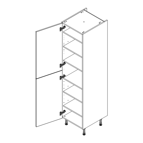
- Page 11 TOWER UNIT 300-600, 2 Door 6 Shelf Assembly Guide Step 8. Attach hinge plates onto both end panels (A) as shown, using 2 screws already located in hinge plates. Hinge side to be mounted in accordance to customer specific kitchen plan. 1826mm 1826mm 1794mm...
- Page 12 TOWER UNIT 300-600, 2 Door 6 Shelf Assembly Guide Screws for attaching to walls are not provided as these vary depending on materials, thickness and construction. Ensure appropriate fixings for wall construction are used. Step 9. Use 2 x 15mm screws (L) to secure each of the L brackets to the rear of the unit at either side.
- Page 13 TOWER UNIT 300-600, 2 Door 6 Shelf Assembly Guide FRONTAL AND HINGE ATTACHMENT Step 1. Align doors to join together using 2 x fixing plates (U) to the back of both frontals. Ensure a 4mm gap is maintained between each frontal once fixed together. Screw in place using 4 x 15mm screws (L) per fixing plate.
- Page 14 TOWER UNIT 300-600, 2 Door 6 Shelf Assembly Guide For Internal Use: FI.WR.INS.040_WKIN00140_TOWER_300_600_2Dr6Shelf_Rev11...
- Page 15 TOWER UNIT 300-600, 2 Door 6 Shelf Assembly Guide For Internal Use: FI.WR.INS.040_WKIN00140_TOWER_300_600_2Dr6Shelf_Rev11...
Need help?
Do you have a question about the Vogue 300 50/50 and is the answer not in the manual?
Questions and answers