Table of Contents
Advertisement
Quick Links
Advertisement
Table of Contents

Related Manuals for Shining 3D EinScan SE


Summary of Contents for Shining 3D EinScan SE
- Page 1 EinScan SE & SP V2 User Manual V3.2.0.4...
-
Page 2: Table Of Contents
Table of Contents Overview Welcome Safety instructions About the document Device Installation Recommended configuration Get installation package Run the installer Activation Register Log in Activation Online activation Offline activation Interface Overview Navigation bar Settings and feedback Other modules Side toolbar Bottom toolbar Performance monitor Keyboard shortcuts... - Page 3 White balance Interface Steps Scan Preparation Object preparation Scanning with turntable Scanning without turntable Markers preparation Project and project group Project group Project Project setting Texture Scanning Scan setting Camera window Brightness Background cutting Align mode With turntable Scanning Start scan / Pause scan / Stop & Delete Global optimization Data edit Edit scanned data...
- Page 4 Post Processing Mesh model Mesh type Mesh optimization Operation Mesh editing Left panel Bottom toolbar Right toolbar Measurement Measurement Create features Align Measurement Save Save data Date sharing Contact us...
-
Page 5: Overview
Overview... -
Page 6: Welcome
This document is related to your safety, lawful rights and responsibilities. Read it carefully before installing and using the product. SHINING 3D Tech Co., Ltd. (hereinafter referred to as "the Company") owns complete intellectual property rights for the contents of this document and, without the written consent of the Company, it's not allowed to copy, transmit, publish, reedit, compile or translate any contents of this document for any purpose or in any form. -
Page 7: Device
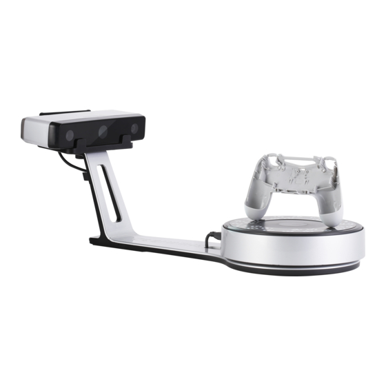
Device The EinScan SE/SP V2 are desktop 3D scanners developed by SHINING 3D, featuring an extensive scanning range for various-sized objects. They offer one-click scanning, automatic calibration, and support color scanning for highly detailed 3D models with colored textures. Compatible with 3D printers, they produce watertight 3D data. - Page 8 Appearances EinScan SE V2 3D Scanner EinScan SP V2 3D Scanner A powerful companion for educators and The expert's choice for enhanced experience: individuals: Precise calibration in a simple way, achieving Easiest 3D scanning experience for non- high accuracy of better than 0.05 mm...
- Page 9 Checklists EinScan SE V2...
- Page 10 Part Scanner Head Turntable Scanner Stand Scanner Bracket Calibration Board Calibration Board Holder Power Adapter USB Cable A USB Cable B Quick Guide...
- Page 11 EinScan SP V2...
- Page 12 Part Scanner Head Turntable Scanner Stand Scanner Bracket Calibration Board Calibration Board Holder Power Adapter USB Cable A USB Cable B Tripod Markers Quick Guide Connection Steps 1. Insert calibration board onto the board holder.
- Page 13 2. Screw the bracket tight to the stand. 3. Mount the turntable securely onto the stand. 4. Attach the scanner head to the bracket.
- Page 14 5. Connect the turnable to the scanner. 6. Plug the power adapter into the scanner's power input port, and then connect the other end to a power outlet. Then connect one end to an available USB port on your computer and the other end into the USB port on the scanner head.
-
Page 16: Installation
Installation To use the scanner, you need to install the EXScan S software first (hereinafter referred to as the "software"). -
Page 17: Recommended Configuration
Recommended configuration MacBook Air (2020、2022) Component Minimum Requirement Apple M1 or better 7-core GPU or better Memory 8 GB RAM or more Storage At least 800MB available Operation system macOS Ventura (macOS 13) or later USB port USB 3.0 MacBook Pro(2021、2022) Component Minimum Requirement Apple M1 or better... -
Page 18: Get Installation Package
Component Minimum Requirement Apple M1 or better 8-core GPU or better Memory 8 GB RAM or more Storage At least 800MB available Operation system macOS Ventura (macOS 13) or later USB port USB 3.0 Get installation package https://www.einscan.com/support/download/ To download the software, go to our website: Run the installer To install the software, locate the .pkg file on your computer, double-click the file, and then follow the on-screen instructions. -
Page 19: Activation
You need a SHINING 3D User Account before activating the device. Register For new users, you need to register a SHINING 3D Passport first, click Register in the pop-up window when launching the software, or click Register a new account in our SHINING 3D Passport website: https://passport.shining3d.com/signup... -
Page 20: Log In
Log in Log in SHINING 3D User Account from the pop-up window when launching EXScan S. If your computer failed to connect to the network: Check the network connection and click Refresh to reconnect to the network. It will jump back to the login interface after successfully connecting to the network. - Page 21 3. Copy the C2V file to the other computer which is connected to Internet. 4. On the computer with network, go to , upload your C2V file in offline https://passport.shining3d.com/login activation page, complete the information then click Activate button to go to download page. 5.
-
Page 22: Interface
Interface Overview Navigation bar... - Page 23 Button Description Device To display the device status: online / offline. Device online: to show the device name. Device offline: click to reconnect the device. Calibration Click on the corresponding position in the navigation bar to start calibration. Scan Click on the corresponding position in the navigation bar to start scanning.
-
Page 24: Settings And Feedback
Settings and feedback Reverse engineering service Function Description Official official website Open the of SHINING 3D to learn about the company’s products and Website information. Facebook Enter SHINING 3D’s Facebook to view product introduction and other operations. - Page 25 Function Description Language Choose the software language. Data editing after After each scan, edit and confirm the scanned data. scanning Factory Default All settings can be restored to the initial settings, and the software will automatically restart.
- Page 26 Display the device name, calibration board number and current software version...
-
Page 27: Other Modules
Check whether the configuration meets the requirement Function Description User Manual Open user manual in default browser. Teamviewer The quick access for remote assistance. Send the ID and password in the pop-up window to our support team for remote assistance. Technical Open our support website... - Page 28 Preview one camera in real time. Click to zoom in or ▶ to open the preview of other camera. Brightness and background cutting are scan-related settings. Manage project group. Please refer to the detailed instructions for use: Project and project group...
-
Page 29: Side Toolbar
Set up scan-related settings. Please refer to the detailed instructions for use: Scan settings Side toolbar Start Scanning | Pause & Delete | Global Optimization Get Started Before and after scanning, you can perform some functions. Other functions... -
Page 30: Bottom Toolbar
Bottom toolbar EinScan SE V2 Various tools are available to edit 3D data and obtain accurate 3D point cloud data. Edit scanned data EinScan SP V2 Various tools are available to edit 3D data and obtain accurate 3D point cloud data. -
Page 31: Keyboard Shortcuts
Index Description Remaining If the available memory is extremely limited, it may cause the system to become sluggish, or Memory even lead to crashes or errors. CPU Usage When the running program consumes a significant portion of the CPU's processing power, it may result in system slowdowns or response delays. - Page 32 Gesture Function Tap and slide Rotate Tap with two fingers and slide Pinch with two fingers Zoom in or out...
-
Page 33: Quick Guide
Quick guide Step 1 Step 2 Ensure device accuracy and scanning quality. Create or open a project group. Calibrate Create a project Step 3 Step 4 Configure the project setting. Scan the object and obtain the data. Set up Scan Step 5 Step 6 Edit scanned data. -
Page 34: Calibration
Calibration With calibration, the scanner parameters are recalculated, which not only ensures the accuracy of the scanner, but also improve the quality of scanning. Note Calibration is required under the following conditions: When the scanner is used for the first time. The scanner was severely shaken or shocked, such as shocked during transportation. - Page 35 Steps 1. Place the calibration board to the proper position on the turntable, facing the 3D scanner. 2. Follow the prompts on the screen to position the calibration board, ensuring that the center crosshair is aligned with the calibration board in both the left and right camera views. 3.
- Page 36 White balance To ensure the accuracy of the texture data, it's recommended to adjust the white balance whenever there is a change in ambient brightness. Caution Don't move the calibration board during calibration. Don't adjust the white balance or scan under strong light, it may cause color deviation. Interface Steps 1.
- Page 37 Note If white balance fails, please recalibrate the white balance. support team If you cannot get the pass result anyway, please contact your supplier or our After successfully calibrating the white balance, click Next to create or open a project group.
- Page 38 Scan...
- Page 39 EinScan SE V2 Basic Scanning Workflow Start Create a Project Project Se ngs Prepara on Scan Se ngs Scanning Pause/Stop & Delete Edit Add Scan Create a new Global Import a Project Project Op miza on Add Scan Edit Alignment...
- Page 40 Mesh Save Finish...
- Page 41 EinScan SP V2 Basic Scanning Workflow Start Create a Project Project Se ngs Prepara on Scan Se ngs Scanning Pause/Stop & Delete Edit Add Scan Create a new Global Import a Project Project Op miza on Add Scan Edit Alignment...
- Page 42 Mesh Save Finish...
- Page 43 Global Markers Scanning Workflow Start Create a Project Open a Global Marker File Prepara on Scan Global Markers Generate Global Markers Scanning Se ngs Scanning Pause/Stop & Delete Add Scan Create a New Project Import a Project Global Op miza on Add Scan Edit Alignment...
- Page 44 Preparation Some preparatory work is required to scan easily and fast with good quality. Object preparation Scanning with turntable Objects with a weight of less than 5 kg. Objects with dimensions greater than 30 x 30 x 30 mm³ and less than 200 x 200 x 200 mm³. Scanning without turntable Objects with dimensions greater than 30 x 30 x 30 mm³...
- Page 45 Markers preparation If the features of the scanned object aren't rich enough, markers can be pasted on the object for scanning alignment. Scanning Range Marker Size 290—480 mm 3 mm Please pay attention to the following details when pasting the markers: Attach the markers evenly and randomly.
- Page 46 Project and project group Create or open a project group before scanning. Project group Project group is the standard file structure of the software. It contains one project or more. Each project contains the scan data of its own. Project group is mainly used in the following scenarios: Project Group Scenario Description...
- Page 47 Note Current project group will be saved automatically. Two ways to open a project group: If the device has been calibrated, open the software and wait for it to fully load. Then, click open project group in the interface. On the scanning interface, click the project group button in the sidebar, and then click open project group in the pop-up window.
- Page 48 icon function instruction note & warning Create new Two ways to create a project: You can create project only when project 1. A project will be created scanner connected. automatically when you create a project group. 2. In scan window, click create a new project.
- Page 49 Project setting Texture Option Description Texture scan on Capture texture data. Texture scan off Unable to make texture adjustment. Note Texture scanning takes a long time and needs to set the correct white balance. After creating the project, this option can't be changed.
- Page 50 Scanning...
- Page 51 Scan setting Following parameters can be set when scanning. Camera window Brightness Adjust the brightness for different material / color of the object to get better scan data. Too high Proper Too low Background cutting When this function is turned on, the background of the scanned object will be automatically shielded. The larger the value is set, the larger the shielding range.
- Page 52 EinScan SE V2 Align Description Mode Turntable After connecting the turntable, you can set the turntable steps, speed, and number of turns of the turntable. Features Automatically complete the alignment by the surface geometric features of the scanned object. This mode is used for objects that can't paste markers and have rich surface features.
- Page 53 EinScan SE V2 Turntable Steps: Before scanning, you can set the number of times (8—180) for one circle of the turntable through this item, and the default value is 8. Turntable Speed: Before scanning, you can set the turntable speed (1—10) through this item, and the default value is 6.
- Page 54 Turntable Steps: Before scanning, you can set the number of times (8—180) for one circle of the turntable through this item, and the default value is 8. Turntable Speed: Before scanning, you can set the turntable speed (1—10) through this item, and the default value is 6.
- Page 55 Scanning Start scan / Pause scan / Stop & Delete You can switch the scanning status by clicking the button in the software. Function Icon Description Scan Scanned data will be stored. Click this button or press the space bar on the keyboard to start scanning.
- Page 56 Data edit You can edit the scanned data when you pause or complete the scanning process. Edit scanned data...
- Page 57 EinScan SE V2 Icon Function Instruction Multi View 6 different view angles to choose. Cutting Plane Create a plane to do quick cut. For more, see Scan Data Edit. EinScan SP V2 Icon Function Instruction Multi View 6 different view angles to choose.
- Page 58 Icon Function Instruction Rectangular Select/Deselect a rectangular area. The selected area is displayed in red. Polygon Select/Deselect a polygon area. Lasso Select/Deselect the area by using the Lasso tool. Straight line Hold down and move the cursor to draw a straight ⇧...
- Page 59 Icon Function Instruction Undo The last deletion will be undone. Cancel Edit Undo all edits, and exit the edit mode. Apply Edit Click the button or space bar to apply the edit, and exit the edit mode. Keyboard shortcuts Shortcut Function Select the area of data ⇧...
- Page 60 Function Keyboard Description shortcut Select all The function is the same as the function on editing bar. ⌘ C m d Unselect The function is the same as the function on editing bar. ⌘ C m d Connected Click the button after selecting a patch of data and all connected Domain region to the selected data will be picked.
- Page 61 EinScan SE V2 Method Instruction Fitting Point Press to select data, and then click Generate Plane. The ⇧ S h i f t L e f t B u t t o n Cloud direction of the plane will be calculated by the software according to the direction of point cloud.
- Page 62 EinScan SE V2 Delete selected point cloud: Data in the reverse direction will be shown in red after checking the box. The red data will be deleted after clicking Apply. Note You can not delete all point cloud data. Invert: Inverse the normal direction of the cutting plane.
- Page 63 Delete selected point cloud/markers: Data/markders in the reverse direction will be shown in red after checking the box. The red data will be deleted after clicking Apply. Note You can not delete all point cloud data. Please keep at least 4 or more markers on the front of the cutting plane.
- Page 64 Other functions Before or after scanning, you can access the other scan functions through the sidebar function buttons. Icon Function Instruction Project Group Create / open a project group. About project group, please refer to Project Group. Align Align the data as you need, please refer to Align. Save Data Save scan data.
- Page 65 Alignment This is how you align multiple projects in one project group. Click on the right side of the interface to enter the project alignment interface.
- Page 66 EinScan SE V2 Mode Description Note 1. Choose By Feature. Regular shaped objects (circular objects and square objects included) or small sized objects aren't 2. Select the project which needs suitable for this mode. alignment in the fixed window and By Feature the floated window.
- Page 67 Mode Description Note 1. Choose By Feature. Regular shaped objects (circular objects and square objects included) or small sized objects 2. Select the project which needs aren't suitable for this mode. alignment in the fixed window and the By Feature floated window.
- Page 68 Post Processing...
- Page 69 Mesh model Meshing is to convert the point cloud into a triangular mesh surface. The data after mesh can be directly used for rendering, measurement or printing. Mesh type Icon Function Instruction Unwatertight Unclosed model stays the way it's scanned. Processing time is quicker than Watertight.
- Page 70 Optimization Instruction Note Filter Optimize the data and improve the - None: No optimization clarity of the data. The higher the - Low: Optimizes data slightly and preserves level, the less the small details . data characteristics - Med: Reduce the noise on the surface of the scan data - High: Reduce the noise on the surface of the scan data and sharpen it powerfully.
- Page 71 Optimization Instruction Note Recommended When turning on, it will automatically use the recommended parameters parameters for meshing. Operation Click Preview to confirm the settings and start meshing. Click to restore. Click Confirm to confirm the mesh result.
- Page 72 Mesh editing Left panel Click to open each function.
- Page 73 Function Instruction Note Texture Brightness and Contrast can be Confirm to apply, Cancel to restore adjusted. Simplification After simplification, the polygon High level may cause detail loss. Set the ratio from numbers, file size and detail of data 1 to 100, the default is 0. will be reduced universally.
- Page 74 Function Instruction Note Flip normal To redefine the front direction of the scanned data in reversal Texture mapping will be design. unavailable after flip Normal Cutting plane Define a plane by drawing a straight line. Delete the selection tool and close the mesh at the intersection. Use the cutting plane to align the mesh to the CSYS.
- Page 75 Icon Function Instruction Open file Open a file (STL, OBJ, PLY) for post processing. Save Data Save scan data. Sketchfab Use your account to share the model. Sketchfab Upload Texture After the post-processing, hole filling on texture scanned data will affect remapping the texture render.
- Page 76 Measurement...
- Page 77 Measurement When you complete the mesh editing, click on the corresponding position in the navigation bar to switch to the measurement interface. Then you can perform operations such as creating features, alignment, and measurements here. Note On the Measurement interface, you can use multi view.
- Page 78 Create features You can measure on the model you just scanned, or you can open a model file to do the measurement. Select the file to be measured or directly drag the file (STL, OBJ, PLY) to the measurement interface. Click to display the menu of creating features.
- Page 79 Point Creation Method Description Note Selected Points Click on the data to select a point. Click Create to create a point. Line-Plane Click on the created line, or select it on the Line and Plane should be Intersection dropdown. created in advanced. The line should not be parallel Click on the created plane, or select it on the to the plane.
- Page 80 Creation Description Note Method 3 Points Fit The plane is generated by 3 points not co-linear. The 3 points can't be on the same line. Click on the data to select one point or click on a previous created feature point. In the Choice list select one of the points to reselect it.
- Page 81 Align Use this mode to change the alignment of the data to the global coordinate. This action is useful for post processing or reverse engineering. Caution The shape and accuracy of the model won't be changed by the movement. After the movement and exiting, the changes are irreversible so you can only reset the model by reloading the original file.
- Page 82 Precise Alignment Click Move to to align the model center with the input coordinates, and the axis direction is adjusted to match the input rotation angle. The coordinate system displayed on the interface is the global coordinate system, in which the direction of the red line is the positive direction of X-axis, green is the positive direction of Y-axis and blue is the positive direction of Z-axis.
- Page 83 Select a feature surface in the plane drop-down menu, and select an axis in the corresponding constraint drop-down menu of the plane. The arrow on the plane corner indicates the positive direction of the plane, and the selected axis direction will be consistent with the plane direction. Select a feature line in the drop-down menu of the line, and select an axis in the drop-down menu of the line.
- Page 84 Measurement Click to enter the measurement interface and the menu is displayed. Click it again to exit. Distance Calculate the distance between two points on the surface of the model. Total is the 3D distance. X, Y and Z are the projection of the segment to the respective planes. Click on the surface of the model to pick two points, the calculation will be done automatically.
- Page 85 Save...
- Page 86 Save data You can save the scanned data. Click to select the save path and the file format, enter the file name as well. Format Data Type Saved as Application ASC (whole Optimized cloud Scan.asc Check the data; piece) points Quick export and no need for post- operation.
- Page 87 Date sharing You can upload the encapsulated data to Sketchfab Click to upload the encapsulated data to , where the title, username and password are required to Sketchfab be provided. You can register an account on the Sketchfab to view the shared models. Caution The files uploaded are in STL format.
- Page 88 Email: einscan_support@shining3d.com Support platform: https://support.einscan.com SHINING 3D Offices APAC Region & Headquarters SHINING 3D Tech Co., Ltd. Hangzhou, China Phone: +86 571 82999050 Add: No. 1398, Xiangbin Road, Wenyan, Xiaoshan, Hangzhou, Zhejiang, China, 311258 EMEA Region SHINING 3D Technology GmbH.
Need help?
Do you have a question about the EinScan SE and is the answer not in the manual?
Questions and answers