
Related Manuals for Taurus Smith Machine Deluxe TF-SM2


Summary of Contents for Taurus Smith Machine Deluxe TF-SM2
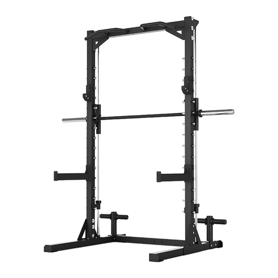
- Page 1 Assembly and Operating Instructions max. 272 kg ~ 120 Min. 112 kg L 197 | B 121 | H 215 FSUKTFSM2.02.01 SKU: TF-SM2 + TF-HR-LR01 + TF-HA3743 Taurus Smith Machine Deluxe...
- Page 2 Smith Machine Deluxe...
-
Page 3: Table Of Contents
Content GENERAL INFORMATION Technical Data Personal Safety Set-Up Place ASSEMBLY General Instructions Scope of Delivery: Smith Machine Assembly: Smith Machine Set-Up Place Scope of Delivery: Low Row Attachment Assembly: Low Row Attachment Scope of Delivery: Pull Up Bar Assembly: Pull Up Bar STORAGE AND TRANSPORT General Instructions TROUBLESHOOTING, CARE AND MAINTENANCE... - Page 4 Smith Machine Deluxe...
- Page 5 European VAT Number: DE813211547 Disclaimer © TAURUS is a registered brand of the company Fitshop GmbH. All rights reserved. Any use of this trademark without the explicit written permission of Fitshop is prohibited. Product and manual are subject to change. Technical data can be changed without advance notice.
- Page 6 ABOUT THIS MANUAL Please carefully read the entire manual before installation and first use. The manual will help you to quickly set up the system and explains how to safely use it. Make sure that all persons exercising with the equipment (especially children and persons with physical, sensory, mental or motor disabilities) are informed about this manual and its contents in advance.
- Page 7 Please pay close attention to the safety and maintenance instructions given here. The contract partner cannot be held liable for damage to health, accidents or damage to the equipment when it is not used in accordance with these instructions. The following safety instructions may appear in this manual: ࣑...
-
Page 8: General Information
GENERAL INFORMATION Technical Data Weight and dimensons Smith Machine: Article weight (gross, including packaging): Box 1: 53 kg Box 2: 63 kg Article weight (net, without packaging): 112 kg Packaging dimensions (L x W x H): Box 1: 133 cm x 47 cm x 16 cm Box 2: 215 cm x 41 cm x 9 cm Set-up dimensions (L x W x H): 197 cm x 121 cm x 215 cm... -
Page 9: Personal Safety
Personal Safety ⚠ DANGER Before you start using the equipment, you should consult your physician that this type of exercise is suitable for you from a health perspective. Particularly affected are persons who: have a hereditary disposition to high blood pressure or heart disease, are over the age of 45, smoke, have high cholesterol values, are overweight and/or have not exercised regularly in the past year. -
Page 10: Set-Up Place
Set-Up Place ⚠ WARNING Do not place the equipment in main corridors or escape routes. ⚠ CAUTION Choose a location in which to place the equipment such that there is enough free space/ clearance to the front, the rear and to the sides of the equipment. The training room should be well ventilated during training and not be exposed to any draughts. -
Page 11: Assembly
ASSEMBLY General Instructions ⚠ DANGER Do not leave any tools, packaging materials such as foils or small parts lying around, as otherwise there is a danger of suffocation for children. Keep children away from the equipment during assembly. ⚠ WARNING Pay attention to the instructions attached to the equipment in order to reduce the risk of injuries. -
Page 12: Scope Of Delivery: Smith Machine
Scope of Delivery: Smith Machine The scope of delivery consist of the following parts. At the beginning, check whether all parts and tools belonging to the device are included in the scope of delivery and whether damage has occurred. In the event of complaints, the contractual partner must be contacted directly. ⚠... - Page 13 Content of Box 1 NUMBER DESCRIPTION QUANTITY Right Bottom Frame Right Bearing Housing Rubber Bumper Right Weight Bar Safety Support Left Bearing Housing Left Weight Bar Safety Support Olympic Bar Holder Left Bottom Frame Bottom Cross Frame Top Cross Frame...
- Page 14 Content of Box 1 NUMBER DESCRIPTION QUANTITY Right Handle Left Handle J-Hook Spotting Arm Olympic Spring Clip Upper beam hook Smith Machine Deluxe...
-
Page 15: Assembly: Smith Machine
Assembly: Smith Machine Before assembly, take a close look at the individual assembly steps shown and carry out the assembly in the order given. NOTICE First loosely screw all parts together and check that they fit properly. Tighten the screws using the tool only when you are instructed to do so. - Page 16 Step 2: Assembly of the Frame Fasten the right front upright frame (1) to the right bottom frame (2) with three screws (H10-14), three washers (W10), three large washers (BW10) and three nuts (N10) in horizontal alignment. Fasten the right front upright frame (1) to the lower right upright frame (2) with two hexagon head screw (H10-2) and two washers (W10) in vertical alignment.
- Page 17 Step 3: Assembly of the Cross Frame Connect the top cross frame (24) to the right front upright frame (1) and the left front upright frame (14) using three screws (H12-14), three large washers (BW10), three washers (W10) and three nuts (N10). Attach 16 long axis’...
- Page 18 Step 4: Assembly of the Right Guide Rod NOTICE Ensure that the internal thread of the guide rod (3) is facing upwards. Loosen the screw set (S8-1) from the holder for the guide rod (3), which can be found on the lower side of the right front upright frame (1).
- Page 19 Step 5: Assembly of the Barbell Insert the weight bar (13) into the openings in the right bearing housing (5) and the left bearing housing (15). Hook in the weight bar (13) and the right weight bar safety support (9).
- Page 20 Step 6: Assembly of the Left Guide Rod NOTICE Ensure that the internal thread of the guide rod (3) is pointing upwards. Ensure that the internal thread of the guide rod (3) is pointing upwards. Loosen the screw set (S8-1) from the holder for the guide rod (3), which can be found on the lower side of the right front upright frame (1).
- Page 21 Step 7: Fitting the Barbell Sleeve and Accessories Attach the weight bar sleeve (16) to the weight bar (13) with one washer (17) and one screw (CH12-3) on each side. Attach the spring clip (32) to both weight bar sleeves (16). Fasten the right handle (25) and the left handle (26) to the top cross frame (24) with two screws (H10-2) and two washers (W10) each.
-
Page 22: Set-Up Place
Set-Up Place ⚠ WARNING Do not place the equipment in main corridors or escape routes. ⚠ CAUTION Choose a location in which to place the equipment such that there is enough free space/ clearance to the front, the rear and to the sides of the equipment. The training room should be well ventilated during training and not be exposed to any draughts. -
Page 23: Scope Of Delivery: Low Row Attachment
Scope of Delivery: Low Row Attachment The scope of delivery consist of the following parts. At the beginning, check whether all parts and tools belonging to the device are included in the scope of delivery and whether damage has occurred. In the event of complaints, the contractual partner must be contacted directly. ⚠... - Page 24 Dia48 mm Inner Cap Bracket Pulley NUMBER DESCRIPTION QUANTITY F60x60mm Outer Cap Lat Bar Clip Chain Long Chain Low Row Bar Lat Bar Hook Upper Cable Lower Cable Smith Machine Deluxe...
-
Page 25: Assembly: Low Row Attachment
NUMBER DESCRIPTION QUANTITY Guide Rod Front Upright Assembly: Low Row Attachment Before assembly, take a close look at the individual assembly steps shown and carry out the assembly in the order given. NOTICE First loosely screw all parts together and check that they fit properly. Tighten the screws using the tool only when you are instructed to do so. - Page 26 Bottom Cross Frame H10-14 H10-13 BW10 H10-15 Smith Machine Deluxe...
- Page 27 Step 2: Mounting the Upper Frame Attach the middle upper frame (11) to the guide rod (8) with two screws (H10-3) and two washers (W10) Fasten the middle upper frame (11) to the front upright (12) with a screw (H10-15), two washers (W10) and a nut (N10).
- Page 28 H10-15 H10-15 H10-3 Top Cross Frame H10-3 Smith Machine Deluxe...
- Page 29 Step 3: Fitting the Cables and Pulleys NOTICE Make sure to install the cables and deflection pulleys at the same time. Guide the bolt end of the upper cable (27) over the deflection pulley P1 (16) and the pulley P2 (16) (see illustration).
- Page 30 Guide the upper cable (27) over the pulley P3 (16) between two brackets (15) using a screw (H10-8), two washers (W10) and a nut (N10). Guide the upper cable (27) over the pulley P4 (16) and the pulley P5 (16). Fasten the deflection pulley P4 (16) and pulley P5 (16) to the middle upper frame (11) with one bolt (H10-13), two pulley bushes (26) and one nut (N10).
- Page 31 Connect the clips (19) to the ends of the short chain (20) and hook the clip onto the weight base tube (1). Guide the end of the lower cable (28) over the pulley P6 (16) and fasten the pulley P6 (16) to the front upright (12) with a screw (H10-13), two deflection pulley bushes (26) and a nut (N10).
- Page 32 Step 4: Fitting the Accessories Attach the lat bar hook (24) to the front upright (12) using a bolt (H10-15), two washers (W10) and a nut (N10). Connect the clip (19) to both ends of the chain (20). Hook a clip(19) onto the end of the upper cable (27). Hook the lat bar (18) into the clip (19).
-
Page 33: Scope Of Delivery: Pull Up Bar
Scope of Delivery: Pull Up Bar The scope of delivery consist of the following parts. At the beginning, check whether all parts and tools belonging to the device are included in the scope of delivery and whether damage has occurred. In the event of complaints, the contractual partner must be contacted directly. ⚠... -
Page 34: Assembly: Pull Up Bar
Assembly: Pull Up Bar Before assembly, take a close look at the individual assembly steps shown and carry out the assembly in the order given. NOTICE First loosely screw all parts together and check that they fit properly. Tighten the screws using the tool only when you are instructed to do so. -
Page 35: Storage And Transport
STORAGE AND TRANSPORT General Instructions ⚠ WARNING The storage location should be chosen so that improper use by third parties or children can be prevented. If your equipment does not have transportation wheels, the equipment must be disassembled before transportation. ࣑... -
Page 36: Troubleshooting, Care And Maintenance
TROUBLESHOOTING, CARE AND MAINTENANCE General Instructions ⚠ WARNING Do not make any improper changes to the equipment. ⚠ CAUTION Damaged or worn components may affect your safety and the life of the equipment. Therefore, immediately replace damaged or worn components. In such a case, contact the contract partner. -
Page 37: Maintenance And Inspection Calendar
Maintenance and Inspection Calendar To avoid damage from body sweat, the equipment must be cleaned with a damp towel (no solvents!) after each training session. The following routine tasks must be performed at the specified intervals: Part Weekly Monthly Quarterly Cables Screw connections Pulleys and cable routing... -
Page 38: Recommended Accessories
RECOMMENDED ACCESSORIES To make your training experience even more efficient and pleasant, we recommend that you add suiting accessories to your fitness equipment. For training equipment like smith machines, weight benches or racks this could for example be a floor mat, which makes your fitness equipment stand more securely and also protects the floor from sweat but it could be also additional weights, handles, foot straps for leg exercises or triceps ropes. -
Page 39: Ordering Spare Parts
The serial number of your equipment is unique. It’s located on a white sticker. The exact position of this sticker is shown in the following illustration. Enter the serial number in the appropriate field. Serial number: Brand / Category: Taurus / multi gym Model Name: Smith Machine Deluxe SKU: TF-SM2... -
Page 40: Parts List: Smith Machine (Tf-Sm2)
Parts List: Smith Machine (TF-SM2) Name Name Qty. Qty. Right Front Upright Frame Right Bottom Frame Front Guide Rod Retaining Ring Right Bearing Housing Copper Cover Linear Bearing Rubber Bumper Right Weight Bar Safety Support Bar Safety Support Sleeve Short Axis Long Axis Weight Bar Left Front Upright Frame... - Page 41 Upper beam hook A6-1 Allen Bolt M6x10 F6-1 Flat Head Bolt M6x10 S8-1 Screw Set M8x10 P10-5 Positioning Bolt M10x35 H10-2 Hex Head Bolt M10x20 H10-14 Hex Head Bolt M10x80 H10-15 Hex Head Bolt M10x85 H10-16 Hex Head Bolt M10x90 CH12-3 Cheese Head Bolt M12x25 BW10...
-
Page 42: Parts List: Low Row Attachment (Tf-Hr-Lr01)
Parts List: Low Row Attachment (TF-HR-LR01) Name Qty. Weight Base Tube Safety Stop Frame Sliding Sleeve Sliding Weight Post Dia33-25mm Sleeve Olympic Spring Clip Weight Holder Guide Rod 60x60 Inner Cap 50x50 Inner Cap Middle Upper Frame Front Upright Foot Tube Dia48 mm Inner Cap Bracket Pulley... -
Page 43: Parts List: Pull Up Bar Attachment (Tf-Ha3743)
A10-2 Allen Bolt M10x20 H10-3 Hex Head Bolt M10x25 H10-8 Hex Head Bolt M10x50 CH5-1 Cheese Head Bolt M5-10 H10-13 Hex Head Bolt M10x75 H10-14 Hex Head Bolt M10x80 H10-15 Hex Head Bolt M10x85 BW10 M10 Big Washer M10 Washer M10 Nut M12 Nut Parts List: Pull Up Bar Attachment (TF-HA3743) -
Page 44: Exploded Drawing: Smith Machine
Exploded Drawing: Smith Machine Smith Machine Deluxe... -
Page 45: Exploded Drawing: Low Row Attachment
Exploded Drawing: Low Row Attachment H10-3 H10-15 H10-13 H10-15 H10-13 H10-8 6 14 CH5-1 A10-2 H10-8 H10-3 A10-2 H10-13 H10-13 CH5-1 BW10 H10-13 H10-14... -
Page 46: Warranty
WARRANTY Products from TAURUS® are subject to strict quality control. However, if a fitness equipment purchased from us does not work perfectly, we take it very seriously and ask you to contact our customer service as indicated. We are happy to help you by phone via our service hotline. - Page 47 Warranty Service Within the warranty period, equipment which develops faults as a result of material or manufacturing defects, will be repaired or replaced at our discretion. Ownership of equipment or parts of equipment which have been replaced is transferred to us. The warranty period is not extended nor does a new warranty period begin following repair or replacement under the warranty.
-
Page 48: Contact
CONTACT �� TECHNIK �� TEKNIK OG SERVICE �� CUSTOMER CARE �� +49 4621 4210-900 80 90 16 50 +44 141 737 2249 or �� �� +44 141 876 3972 �� +49 4621 4210-945 +49 4621 4210-698 �� �� info@fitshop.dk customercare@fitshop.co.uk ��... - Page 49 LIVE FITNESS WEBSHOP AND SOCIAL MEDIA The Fitshop Group is Europe’s largest specialist for https://www.fitshop.co.uk/ home fitness equipment with currently 70 stores www.fitshop.co.uk/blog/ and one of the world’s most renowned online mail order companies for fitness equipment. Fitshop UK is part of the Fitshop Group. Private www.facebook.com/fitshop.co.uk customers order via the 25 web shops in the respective national language or have their...
- Page 50 Notes Smith Machine Deluxe...
- Page 52 Taurus Smith Machine...
Need help?
Do you have a question about the Smith Machine Deluxe TF-SM2 and is the answer not in the manual?
Questions and answers