
Subscribe to Our Youtube Channel
Related Manuals for Taurus TF-PS-90


Summary of Contents for Taurus TF-PS-90
- Page 1 Assembly Instructions ~ 75 Min. 120 kg L 27 | W 64 | H 209 TFPS90.01.05 Art. No. TF-PS-90 Taurus Design Line Single Pulley...
- Page 2 Single Pulley...
-
Page 3: Table Of Contents
Content GENERAL INFORMATION Technical Data Personal Safety Set-Up Place ASSEMBLY General Instructions Scope of Delivery Assembly 2.3.1 Assembly (left) 2.3.2 Assembly (right) Cable Adjustment STORAGE AND TRANSPORT General Instructions TROUBLESHOOTING, CARE AND MAINTENANCE General Instructions Faults and Fault Diagnosis Maintenance and Inspection Calendar DISPOSAL RECOMMENDED ACCESSORIES ORDERING SPARE PARTS... - Page 4 Single Pulley...
- Page 5 With Taurus® fitness equipment, the focus is on what sport is all about: maximum performance! Therefore, the equipment is developed in close consultation with athletes and sports scientists.
- Page 6 ABOUT THIS MANUAL Please carefully read the entire manual before installation and first use. The manual will help you to quickly set up the system and explains how to safely use it. Make sure that all persons exercising with the equipment (especially children and persons with physical, sensory, mental or motor disabilities) are informed about this manual and its contents in advance.
-
Page 7: General Information
GENERAL INFORMATION Technical Data Weight and Dimensions: Weight block (67,5 kg) Package dimensions (L x W x H) approx.: No. 1: 211 cm x 67 cm x 15 cm 59.6 kg No. 2: 211 cm x 40 cm x 4 cm 5.4 kg No. -
Page 8: Personal Safety
Personal Safety DANGER ⚠ Before you start using the equipment, you should consult your physician that this type of exercise is suitable for you from a health perspective. Particularly affected are persons who: have a hereditary disposition to high blood pressure or heart disease, are over the age of 45, smoke, have high cholesterol values, are overweight and/or have not exercised regularly in the past year. -
Page 9: Set-Up Place
Set-Up Place WARNING ⚠ Do not place the equipment in main corridors or escape routes. ⚠ CAUTION Choose a location in which to place the equipment such that there is enough free space/ clearance to the front, the rear and to the sides of the equipment. The training room should be well ventilated during training and not be exposed to any draughts. -
Page 10: Assembly
ASSEMBLY General Instructions ⚠ DANGER Do not leave any tools, packaging materials such as foils or small parts lying around, as otherwise there is a danger of suffocation for children. Keep children away from the equipment during assembly. ⚠ WARNING Pay attention to the instructions attached to the equipment in order to reduce the risk of injuries. -
Page 11: Scope Of Delivery
Scope of Delivery The scope of delivery consist of the following parts. At the beginning, check whether all parts and tools belonging to the device are included in the scope of delivery and whether damage has occurred. In the event of complaints, the contractual partner must be contacted directly. CAUTION ⚠... -
Page 12: Assembly
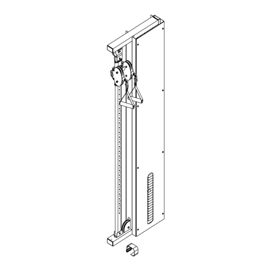
Assembly Before assembly, take a close look at the individual assembly steps shown and carry out the assembly in the order given. NOTICE First loosely screw all parts together and check that they fit properly. Tighten the screws using the tool only when you are instructed to do so. 2.3.1 Assembly (left) Step 1... - Page 13 Step 2 WARNING ⚠ Check whether the condition of your walls is suitable for mounting this unit. To do this, contact your contract partner. Fasten the main frame (1) with four bolt sets (28).
- Page 14 Step 3 NOTICE Before installing the front covers, Make sure that the bolt hole faces in the direction of the main frame like in the footate below. (also applies to step 11). Fasten the pulley housings (13) to the cable height adjuster (7) with two bolts (31), four washers (41) and two nuts (45).
- Page 16 Step 4 NOTICE The pulleys (18) are fixed simiultaneously with the cable (26) Remove one pulley (18) from each of the pulley housings (13) by loosening two bolts (34) and two nuts (46). Guide the ball end of the cable (26) through the left pulley housing (13) and re-fasten the previously removed pulley (18) with a bolt (34) and a nut (46).
- Page 18 Step 5 Remove the guide rod retainer (8). NOTICE Check the number of weight plates of the weight block (12). If you have a total of 14 weight plates, use the spacers (15) when assembling the weight block. If you have 19 weight plates, skip this step.
- Page 20 Step 6 Fix the panel (3) to the two front covers (5) with eight screws (37) and eight rubber gaskets (44). Single Pulley...
-
Page 22: Assembly (Right)
2.3.2 Assembly (right) Step 7 Remove the upright frame (2) along with the cable height adjuster (7) from the main frame (1) by loosening the two bolts (33), four washers (42) and two nuts (46). Loosen the two bolts (34) and two nuts (46) from the main frame (1). Remove the pulley (18) from the guide rod retainer (8) by loosening the two screws (40), the bolt (34) and the nut (46). - Page 24 Step 8 Turn the main frame (1) around. Reattach the upright frame (2) along with the cable height adjuster (7) to the main frame (1) using the bolts, washers and nuts previously removed in step 7. Refasten the two bolts (34) and the two nuts (46) on the main frame (1). Single Pulley...
- Page 25 Step 9 Fasten the two rear covers (6) to the main frame (1) with eight screws (37). Fasten the four L-shaped brackets (14) to the main frame (1) with eight screws (38) and eight spring washers (43). Place the two end caps (19) on the main frame (1).
- Page 26 Step 10 ࣑ ATTENTION The supplied assembly material for wall mounting is not suitable for every wall. Pay attention to the condition of your wall to determine which assembly material is suitable for your wall. The contractual partner accepts no liability for any damage to the wall. Make sure that there are no cables or wires running in the wall where you attach the training equipment.
- Page 27 Step 11 Fasten the two pulley housings (13) to the cable height adjuster (7) with two bolts (31), four washers (41) and two nuts (45). Attach the two front covers (5) to the main frame (1) with eight bolts (39).
- Page 28 Step 12 NOTICE The pulleys (18) are fixed simiultaneously with the cable (26) Remove one pulley (18) from each of the pulley housings (13) by loosening two bolts (34) and two nuts (46). Guide the ball end of the cable (26) through the left pulley housing (13) and re-fasten the previously removed pulley (18) with a bolt (34) and a nut (46).
- Page 30 Step 13 Remove the guide rod retainer (8). NOTICE Check the number of weight plates of the weight block (12). If you have a total of 14 weight plates, use the spacers (15) when assembling the weight block. If you have 19 weight plates, skip this step.
- Page 32 Step 14 Fix the panel (3) to the two front covers (5) with eight screws (37) and eight rubber gaskets (44). Single Pulley...
- Page 34 Step 15 Remove one pulley (18) each from the two pulley housings (13). To do this, loosen the two bolts (34) and the two nuts (46). Guide the ball end of the cable (26) through the two pulleys (18) located in the right pulley housing (13).
-
Page 36: Cable Adjustment
Cable Adjustment The cables should be tensioned so that the top weight plate is just resting on the other weight plates. As soon as the top weight plate does not rest on the other weight plates, the cable should be STEP 6 Cable Tension Adjustment extended. -
Page 37: Storage And Transport
STORAGE AND TRANSPORT General Instructions ⚠ WARNING The storage location should be chosen so that improper use by third parties or children can be prevented. If your equipment does not have transportation wheels, the equipment must be disassembled before transportation. ࣑... -
Page 38: Troubleshooting, Care And Maintenance
TROUBLESHOOTING, CARE AND MAINTENANCE General Instructions ⚠ WARNING Do not make any improper changes to the equipment. CAUTION ⚠ Damaged or worn components may affect your safety and the life of the equipment. Therefore, immediately replace damaged or worn components. In such a case, contact the contract partner. -
Page 39: Maintenance And Inspection Calendar
Maintenance and Inspection Calendar To avoid damage from body sweat, the equipment must be cleaned with a damp towel (no solvents!) after each training session. The following routine tasks must be performed at the specified intervals: Part Weekly Monthly Quarterly Cables Screw connections Pulleys and cable routing... -
Page 40: Recommended Accessories
RECOMMENDED ACCESSORIES To make your training experience even more efficient and pleasant, we recommend that you add suiting accessories to your fitness equipment. For training equipment like smith machines, weight benches or racks this could for example be a floor mat, which makes your fitness equipment stand more securely and also protects the floor from sweat but it could be also additional weights, handles, foot straps for leg exercises or triceps ropes. -
Page 41: Ordering Spare Parts
The exact position of this sticker is shown in the following illustration. Enter the serial number in the appropriate field. Serial number: Brand / Category: Taurus / Multi Gym Model Name: Taurus Design Line Single Pulley Article Number: TF-PS-90 / TF-PS-M-90 / TF-PULL-SINGLE/ TF-PULL-SINGLE-M... -
Page 42: Parts List
Parts List Name Qty. 1901-1 MAIN FRAME 1pcs 1901-2 UPRIGHT FRAME 1pcs 1901-3 PANEL 1pcs 1901-4 GUIDE ROD 2pcs 1901-5 FRONT COVER 2pcs 1901-6 REAR COVER 2pcs 1901-7 CABLE HEIGHT ADJUSTER 1pcs 1901-8 GUIDE ROD RETAINER 1pcs 1901-9 DOUBLE PULLEY BLOCK 1pcs 1901-10 TOP PLATE... - Page 43 1901-30A PLASTIC GUIDE ROD HOLDER 2pcs 1901-31 1/2" X 4 1/4" HEX BOLT 2pcs 1901-32 3/8" X 3" HEX BOLT 1pcs 1901-33 3/8" X 2" HEX BOLT 2pcs 1901-34 3/8" X 1-3/4" HEX BOLT 10pcs 1901-35 5/16" X 5/8" INNER HEX SCREW 2pcs 1901-36 5/16"...
-
Page 44: Exploded Drawing
Exploded Drawing OVERVIEW 14 38 Single Pulley... -
Page 45: Warranty
WARRANTY Training equipment from Taurus® is subject to strict quality control. However, if a fitness equipment purchased from us does not work perfectly, we take it very seriously and ask you to contact our customer service as indicated. We are happy to help you by phone via our service hotline. - Page 46 Warranty Conditions For the warranty to be valid, the following steps must be taken: Please contact our customer service by email or phone. If the product under warranty has to be sent in for repair, the seller bears costs. After expiry of the warranty, the buyer bears the costs of transport and insurance.
-
Page 47: Contact
CONTACT TECHNIK TEKNIK OG SERVICE TECHNIQUE & SERVICE �� �� �� +49 4621 4210-900 80 90 16 50 +33 (0) 189 53 09 84 +49 4621 4210-945 +49 4621 4210-933 �� +49 4621 4210-698 �� �� info@fitshop.dk info@fitshop.fr �� technik@sport-tiedje.de ��... - Page 48 LIVE FITNESS WEBSHOP AND SOCIAL MEDIA Sport-Tiedje is Europe’s largest specialist store www.sport-tiedje.co.uk for home fitness equipment with currently over www.sport-tiedje.de/blog 70 stores and one of the world’s most renowned online mail order companies for fitness equipment. Private customers order via the 25 www.facebook.com/SportTiedje web shops in the respective national language or have their desired equpiment assembled on...
- Page 49 Notes...
- Page 50 Notes Single Pulley...
- Page 52 Taurus Single Pulley Design Line...
Need help?
Do you have a question about the TF-PS-90 and is the answer not in the manual?
Questions and answers