
Subscribe to Our Youtube Channel
Related Manuals for Headsight CASE-IH FLAGSHIP 010 Series


Summary of Contents for Headsight CASE-IH FLAGSHIP 010 Series
- Page 1 HEADSIGHT HEADSIGHT ® ® INSTALLATION & OPERATION MANUAL CASE-IH CASE-IH FLAGSHIP FLAGSHIP x x 010, 010, x x 120, 120, x x 230, 230, x x 240, 240, x x 250 09010201m HEADSIGHT.COM | 574.546.5022...
- Page 2 This icon designates an important instruction. Suggestions If you have any suggestions to improve this manual please call 574-546-5022 or email info@headsight.com. Disclaimers HEADSIGHT, HORIZON, PINPOINT, FORESIGHT, FEATHERSIGHT, TRUESENSE, TERRAHAWK, INSIGHT, the Headsight logo, the Horizon logo, and Terrahawk logo are trademarks of Headsight Harvesting Solutions.
-
Page 3: Table Of Contents
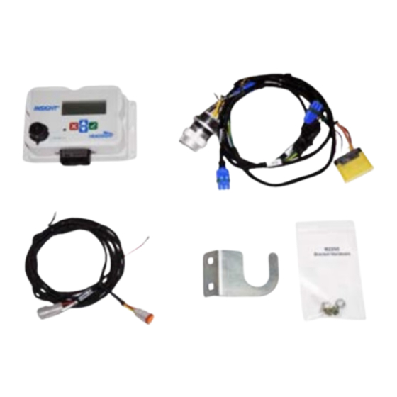
Schematics ��������������������������������������������������������������������������������������24 Table of Contents Insight Harness - Typical ������������������������������������������������������������� Parts �������������������������������������������������������������������������������������������� Safety Information ������������������������������������������������������������������������������ Mounting Bracket and Harness �������������������������������������������������������� Safety Stop �������������������������������������������������������������������������� Statement of Limited Warranty ����������������������������������������������������������������� Installation ������������������������������������������������������������������������������������� Installation Overview ���������������������������������������������������������������� Insight ® Systems �������������������������������������������������������������������� Factory “Prewired” Headers ���������������������������������������������������������������������� Insight ®... -
Page 4: Safety Information
Installation Overview 1. Perform all combine and header manufacturer safety precautions for servicing header. To install a Headsight system, follow the steps below in order. 2. Insert stop to prevent movement of header. 3. Set combine parking brake. 1. Install the Header components. -
Page 5: Insight ® Systems
1. Connect sensor wiring to main Headsight harness. • Factory “Prewired” Headers Sensor location as viewed from operator’s seat Left Left Center Center Right Center Right Some header models are “prewired” for Headsight sensors and controllers. 2 Sensor • Honeybee 4000 •... -
Page 6: Insight Power Wire
Feathersight ® Option Installation (if equipped) Insight Power Wire No Power Wire is needed for all Midrange & CIH x250 s/n 1. If combine already has a feederhouse pressure sensor YKG239890 & newer. Skip to the next section. connect “Y” harness in-line with combine feeder house pressure sensor on main valve block. -
Page 7: Basic Harness Only Systems
Setup Insight ® After completing this section go directly to Combine Ground Calibration section. 1. Connect sensor wiring to main Headsight harness. These steps must be performed the first time the Insight box is powered up and each • time it is reset. They do not need to be redone each time the Insight box is calibrated. -
Page 8: Calibrate Insight
Calibrate Insight Combine Calibration When you initialize Insight, you will be led directly to this calibration routine. If you wish A full combine calibration must be completed on new installations or if a component of the to recalibrate at any time - select “>>Perform Calibration” on the Insight main menu. header control system is changed on the combine. -
Page 9: Ground Calibration - Generation 1 Software
9. Verify that the combine now has the “wavy line” icon Settings 10. Readjust height setpoint(s) to desired working position. Insight Settings See the 09010001 Insight Users Manual/Setup for information on settings available in Insight. • 2 or 4 Sensor Tilt •... -
Page 10: Ahhc Settings
1. Be sure you have the initial settings entered and have calibrated Insight. • Height/Tilt Response Rate 2. Operate the Headsight system exactly like you would use your combine OEM height control system. • Normal or Fast 3. Fine tune all combine speed and sensitivity adjustments for best performance. -
Page 11: Advanced Information
1. Use PFI-250-P power update adapter. Theory of Operation • Contact Headsight to order this part if needed 2. Remove metal shield from left side of feederhouse. A review of the following points will help the service technician to understand the complete system, which will help diagnose specific problems. -
Page 12: Diagnostics
Diagnostics Reading Voltages in Combine On the Pro 700 Monitor Before working on combine or under header always: 1. Start by choosing Back 1. Perform all combine and header manufacturer safety precautions for servicing header. 2. Insert stop to prevent movement of header. 2. -
Page 13: Troubleshooting-Sensors And Harnesses
“Insight Status “Wavy Line” mode not enabled Turn on AHHC, see Operation section If you have a Headsight Sensor tester, Verify sensor is connected to extension If sensor cannot be adjusted to achieve Light Diagnostics”) of this manual use it to test the sensor. - Page 14 Then finish calibration Sensors too short Install extensions on corn sensors. Cannot operate head low enough Calibration not properly completed Perform Insight and Combine calibration on flat level surface Special software needed Contact Headsight regarding optional products Foresight and/or Feathersight...
- Page 15 Diagnostics>>Left & Right Height ground on pin (black wire) Outputs No Ground. Some early Insight Call Headsight - ground must be V head fully lowered harnesses (r ) had Ground in pin spliced to ground wire in pin V sensors off ground...
- Page 16 Schematics Insight Harness - Typical The Insight Harness schematic is the main harnesses used for all applications in this manual. A number of variations are available. The following schematics are provided for troubleshooting and installation purposes only. Unauthorized uses, such as using them to replicate harnesses for resale, are strictly prohibited under copyright law.
- Page 17 Headsight is for the sole purpose of identifying such goods and shall not create an express warranty that the goods shall conform to such description.
- Page 18 574.546.5022 • 574.546.5760 4845 3B Rd • Bremen, IN 46506 info@headsight.com www.headsight.com...
Need help?
Do you have a question about the CASE-IH FLAGSHIP 010 Series and is the answer not in the manual?
Questions and answers