Headsight TRUESIGHT 2 Manual
Hide thumbs
Also See for TRUESIGHT 2:
- Installation & operation manual (46 pages) ,
- Installation & operation manual (64 pages) ,
- Installation & operation manual (40 pages)

Related Manuals for Headsight TRUESIGHT 2


Summary of Contents for Headsight TRUESIGHT 2
- Page 1 TRUESIGHT 2 TRUESIGHT 2 HEADER INSTALLATION AGCO AGCO 3000 3000 09052004c HEADSIGHT.COM | 574.546.5022...
- Page 2 This Page Is Intentionally Left Blank...
-
Page 3: Identify The Components
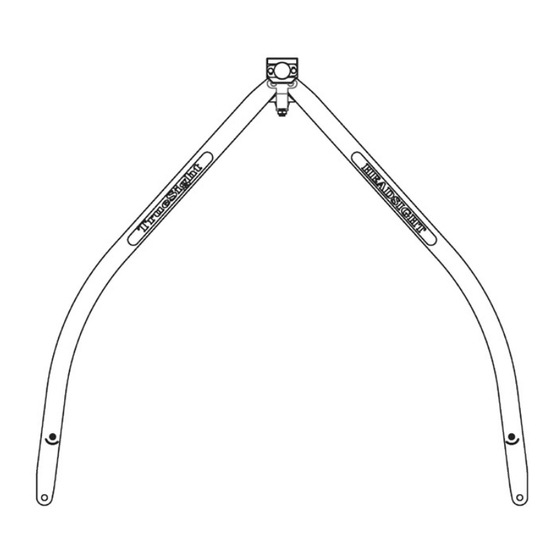
Identify the Components 1. Crop sensor assembly • HT 2501 - Crop sensor assembly 2. Crop sensor whiskers • HT 2695 - Arm 3. Crop sensor extension harness (header) • HT 2808 - Crop sensor extension harness 4. Mounting Kit •... - Page 4 Crop Sensor Assembly Arms have holes at both ends. Make sure the correct end of the arms are mounted to the sensor assembly for your row spacing. For row spacings 15” and narrower, cut and drill poly arms at the locations marked on the poly arms.
-
Page 5: Width Adjustment
Width Adjustment 1. Loosen the jamb nut indicated. 2. Turn arm adjustment screen using a hex (Allen) wrench. • Adjust arm width to row spacing plus 2 inches (e.g. adjust to 32 " for 30 " row spacing) 3. Tighten jamb nut. Arm Width The poly arm width setting gradually decreases. -
Page 6: Safety First
Safety First Before working on combine or under header always: 1. Perform all combine and header manufacturer safety precautions for servicing header. 2. Insert stop to prevent movement of header. 3. Turn off combine and remove key from ignition. 4. Set combine parking brake. 5. - Page 7 Install Crop Sensor 1. Attach the sensor to the mounting bracket as shown. • Use provided Thread - Locking flange bolts • Do not tighten bolts until height is adjusted 2. Remove rear two bolts from snout tip. 3. Cut out poly as shown. •...
- Page 8 Routing Sensor Wiring Properly routing the wiring is the most critical part of the installation process. Please take time to ensure that you have allowed sufficient slack for motion as well as sufficient clearance from moving header parts or crop flow. Removing Connector for Tight Access When routing the wiring, there may be times when you would like to route the wiring through a small hole.
- Page 9 Routing Wiring 1. Connect the wiring to the sensor. • Ensure connection is properly aligned and seated • Push gently but firmly until it clicks 2. Fasten wiring with cable clamps on both sides of the connection. • Allow slight ( 1 / 2 ”) slack near sensor 3.
- Page 10 This Page Is Intentionally Left Blank...
- Page 11 Parts - Mounting Kit ITEM QTY. PART NUMBER DESCRIPTION HT2746 Mounting Bracket HT2694 Bubble Shield B2746 Hardware Kit 08200226 Bolt w/Loctite 08100102 Large Clamp 08100101 Small Clamp 08200107 Screw 08200222 Torx Screw 08300105 Torx Socket 08300102 Zip Ties...
- Page 12 574.546.5022 • 574.546.5760 4845 3B Rd • Bremen, IN 46506 info@headsight.com www.headsight.com...
Need help?
Do you have a question about the TRUESIGHT 2 and is the answer not in the manual?
Questions and answers