
Related Manuals for protech POS-6920 Series


Summary of Contents for protech POS-6920 Series
- Page 1 USER’S MANUAL POS-6920 Series POS System Powered by ® ® Intel Atom Platform POS-6920 Series M2...
- Page 2 Preface POS-6920 Series POS System With LCD / Touchscreen PREFACE COPYRIGHT NOTICE This user’s manual is meant to assist users in installing and setting up the system. The information contained in this document is subject to change without any notice.
- Page 3 Preface FCC NOTICE This equipment has been tested and found to comply with the limits for a Class A digital device, pursuant to part 15 of the FCC Rules. These limits are designed to provide reasonable protection against harmful interference when the equipment is operated in a commercial environment.
- Page 4 Contents TABLE OF CONTENTS CHAPTER 1 INTRODUCTION About This Manual ............POS System Illustration ..........System Specifications ........... Safety Precautions ............CHAPTER 2 SYSTEM CONFIGURATION Jumper & Connector Quick Reference Table ....Component Locations ........... How to Set the Jumpers ..........COM Port Connector …………………………………...
-
Page 5: Table Of Contents
Contents CHAPTER 3 SOFTWARE UTILITIES Introduction ..............® Intel Chipset Software Installation Utility ....VGA Driver Utility …………………………….…….. LAN Driver Utility ............Sound Driver Utility ............. Touch Screen Driver Utility ……………..…………… Fingerprinter Driver Utility (Optional) ………………. RFID Module Driver Utility (Optional) ……………… CHAPTER 4 AMI BIOS SETUP Introduction .............. - Page 6 Contents APPENDIX B TECHNICAL SUMMARY Block Diagram ................. Interrupt Map ................DMA Channels Map ..............I/O Map ..................Watchdog Timer Configuration ..........Flash BIOS Update ……............APPENDIX C QUICK MANUAL Assembly Procedure of VFD ........... Assembly Procedure of 2nd Display ........i-Button Decoder API ..............
- Page 7 CHAPTER INTRODUCTION This chapter gives you the information for the POS-6920. It also outlines the system specifications. Sections included: About This Manual POS System Illustration System Specifications Safety Precautions Experienced users can jump to chapter 2 on page 2-1 for a quick start. Page:1-1...
- Page 8 Chapter 1 Introduction 1-1. ABOUT THIS MANUAL Thank you for purchasing our POS-6920 Series System. The POS-6920 is an updated system designed to be comparable with the highest performance of IBM AT personal computers. The POS-6920 provides faster processing speed, greater expandability and can handle more tasks than before.
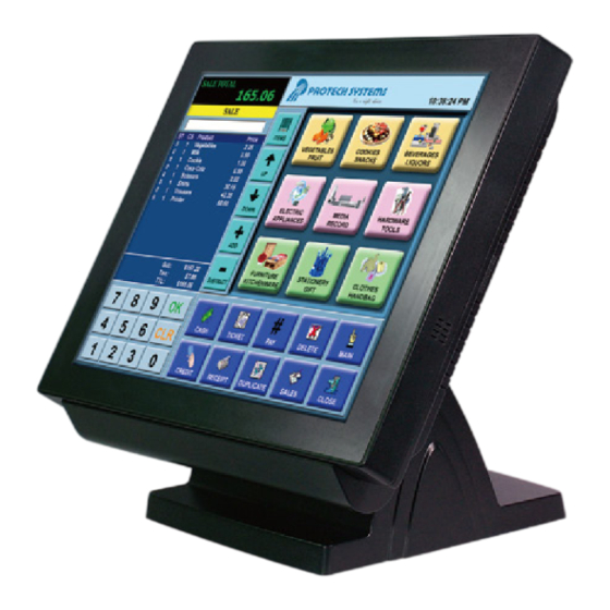
- Page 9 Chapter 1 Introduction 1-2. POS SYSTEM ILLUSTRATION POS-6920 with Stand Front View Rear View Side View Top View Bottom View ′ Page: 1-3 POS-6920 SERIES USER S MANUAL...
- Page 10 Chapter 1 Introduction I/O View Quarter View Page: 1-4 ′ POS-6920 SERIES USER S MANUAL...
- Page 11 1 x RJ45 (COM1), 2 x DB-9(COM 2/3), 1 x Wafer (COM4_l) +5/12V Selectable (COM 1~4) Universal Serial Bus Port: 4 x USB2.0 ports 1 x USB2.0 on side bezel LAN Function: 1 x 10/100/1000 Mbps Audio Function: 1 x 2W Speaker ′ Page: 1-5 POS-6920 SERIES USER S MANUAL...
- Page 12 MSR / i-Button / Fingerprint (Optional): External vertical module, MSR, Read only, JIS-I or II, ISO Tracker 1+2+3; i-button (PS/2 KB Interface) + Fingerprint (USB Interface) RFID (Optional): Read / Write, ISO 14443A 13.56MHz (USB Interface) Page: 1-6 ′ POS-6920 SERIES USER S MANUAL...
- Page 13 Place your POS-6920 on a sturdy, level surface. Be sure to allow enough space around the system to have easy access needs. b. Avoid installing your POS-6920 Series POS system in extremely hot or cold places. c. Avoid exposure to sunlight for a long period of time (for example, in a closed car in summer time.
- Page 14 If heavy stains are present, moisten a cloth with diluted neutral washing agent or alcohol and then wipe thoroughly with a dry cloth. d. If dust is accumulated on the case surface, remove it by using a special vacuum cleaner for computers. Page: 1-8 ′ POS-6920 SERIES USER S MANUAL...
- Page 15 CHAPTER SYSTEM CONFIGURATION Helpful information that describes the jumper and connector settings, and component locations. Sections included: Jumper & Connector Quick Reference Table Component Locations Configuration and Jumper settings Connector Pin Assignments Page 2-1...
- Page 16 SATA & SATA Power Connector SATA1, JPWR_4P1, SATA2 2-23 Touch Panel Connector TOUCH1, TOUCH2 2-24 Touch Panel Selection JP12 2-25 Clear CMOS Data Selection 2-26 Compact Flash Connector 2-27 Printer Connector LPT1 Page: 2-2 ’ POS-6920 SERIES USER S MANUAL...
- Page 17 Chapter 2 System Configuration 2-2. COMPONENT LOCATIONS M/B: PROX-A6920LF POS-6920 Mainboard Connector, Jumper and Component locations Page: 2-3 ’ POS-6920 SERIES USER S MANUAL...
- Page 18 PIN1 & PIN2 to create one setting and shorting. You can either connect PIN2 & PIN3 to create another setting. The same jumper diagrams are applied all through this manual. The figure below shows what the manual diagrams look and what they represent. Page: 2-4 ’ POS-6920 SERIES USER S MANUAL...
- Page 19 Chapter 2 System Configuration JUMPER DIAGRAMS JUMPER SETTINGS Page: 2-5 ’ POS-6920 SERIES USER S MANUAL...
- Page 20 “12V” for three COM ports or above; otherwise, the system may shut down due to power deficiency. COM1: COM1 Connector The pin assignments are as follows: ASSIGNMENT DCD1 RXD1 COM1 TXD1 DTR1 DSR1 RTS1 CTS1 RI / +5V / +12V selectable Page: 2-6 ’ POS-6920 SERIES USER S MANUAL...
- Page 21 Refer to the Pole VFD assembly procedures in Appendix C Quick Manual. All COM ports are selectable for RI, +5V and +12V. Refer to the section 2-5 COM Port RI & Voltage Selection. Page: 2-7 ’ POS-6920 SERIES USER S MANUAL...
- Page 22 *** Manufacturing Default – RI Caution: When using a 72W power adaptor, do not set the voltage at “12V” for three COM ports or above; otherwise, the system may shut down due to power deficiency. Page: 2-8 ’ POS-6920 SERIES USER S MANUAL...
- Page 23 Chapter 2 System Configuration 2-6. VGA CONNECTOR VGA1: VGA Connector The pin assignments are as follows: ASSIGNMENT VGA1 GREEN BLUE DDCA DATA HSYNC VSYNC DDCA CLK Page: 2-9 ’ POS-6920 SERIES USER S MANUAL...
- Page 24 The jumper settings are as follows: JUMPER SELECTION JUMPER SETTINGS ILLUSTRATION i-Button COM 3 (default) *** Manufacturing Default – COM3 When the jumpers are set as ‘i-Button’, the COM3 connector is not functional. Page: 2-10 ’ POS-6920 SERIES USER S MANUAL...
- Page 25 Chapter 2 System Configuration 2-9. LAN CONNECTOR LAN1: LAN Connector. The pin assignments are as follows: ASSIGNMENT LAN1_MDIP0 LAN1_MDIN0 LAN1_MDIP1 LAN1_MDIN1 LAN1_MDIP2 LAN1_MDIN2 LAN1_MDIP3 LAN1_MDIN3 Page: 2-11 ’ POS-6920 SERIES USER S MANUAL...
- Page 26 2-10. USB CONNECTOR JRJ45USB1: USB Connector The pin assignments are as follows: ASSIGNMENT USB0- JRJ45USB1 USB0+ USB1- USB1+ USB1: USB Connector The pin assignments are as follows: ASSIGNMENT USB2- USB1 USB2+ USB3- USB3+ Page: 2-12 ’ POS-6920 SERIES USER S MANUAL...
- Page 27 Chapter 2 System Configuration USB3: Internal USB Connector The pin assignments are as follows: ASSIGNMENT USB6- USB6+ VCC5 USB5: USB Connector The pin assignments are as follows: ASSIGNMENT USB8- USB8+ VCC5 Page: 2-13 ’ POS-6920 SERIES USER S MANUAL...
- Page 28 The pin assignments are as follows: ASSIGNMENT KDAT MDAT V5SB KCLK MCLK 2-12. RESET/NMI WATCHDOG SELECTION JP4: Reset/NMI Watchdog Selection The jumper settings are as follows: JUMPER SELECTION JUMPER SETTING ILLUSTRATION Reset (default) ***Manufacturing Default – Reset Page: 2-14 ’ POS-6920 SERIES USER S MANUAL...
- Page 29 Read I/O space register "50E"h (GPIO 20) Definition (bit4) 2-14. CASH DRAWER POWER SELECTION JP13: Cash Drawer Power Selection The jumper settings are as follows: JUMPER SELECTION JUMPER SETTING ILLUSTRATION +12V +24V (default) *** Manufacturing Default – +24V Page: 2-15 ’ POS-6920 SERIES USER S MANUAL...
- Page 30 LED_2: Power, HDD, LAN indication LED Connector The pin assignments are as follows: ASSIGNMENT PWR_LED HDD_LED LAN_Link JUSBLED1: Power, HDD, LAN indication LED Connector The pin assignments are as follows: ASSIGNMENT ASSIGNMENT PWR_LED HDD_LED LAN_Link LAN_State Page: 2-16 ’ POS-6920 SERIES USER S MANUAL...
- Page 31 J3: Provide 12 Voltage Connector The pin assignments are as follows: ASSIGNMENT VCC12 VCC12 2-18. POWER SWITCH CONNECTOR SW1, SW2, SW3: Power Switch Connector The pin assignments are as follows: ASSIGNMENT PWR_SW Page: 2-17 ’ POS-6920 SERIES USER S MANUAL...
- Page 32 PRT_PWR1: Power for Thermal Printer Connector The pin assignments are as follows: ASSIGNMENT VCC24SB VCC24SB 2-21. EXTERNAL SPEAKER CONNECTOR SPK1: External Speaker Connector The pin assignments are as follows: ASSIGNMENT SPK_GND SPK_OUT Page: 2-18 ’ POS-6920 SERIES USER S MANUAL...
- Page 33 The pin assignments are as follows: ASSIGNMENT +12V LVDS_BKLTEN BRCTR 2-23. BACKLIGHT TYPE SELECTION JP3: Backlight Type Selection The jumper settings are as follows: JUMPER SELECTION JUMPER SETTING ILLUSTRATION CCFL (default) *** Manufacturing Default – CCFL Page: 2-19 ’ POS-6920 SERIES USER S MANUAL...
- Page 34 KB_CLK_C (Input) KB_DATA_C (Input) KB_DATA (Output) 2-25. LVDS CONNECTOR LVDS1: LVDS connector The pin assignments are as follows: ASSIGNMENT ASSIGNMENT LVDS_VCC CLKO+ CLKO- RINO2+ RINO2- RINO1+ RINO1- RINO0+ RINO0- RINO3+ RINO3- LVDS_VCC LVDS_VCC Page: 2-20 ’ POS-6920 SERIES USER S MANUAL...
- Page 35 Chapter 2 System Configuration 2-26. SATA & SATA POWER CONNECTOR SATA1: Serial ATA Connector The pin assignments are as follows: ASSIGNMENT SATA1 JPWR_4P1: Serial ATA Power Connector The pin assignments are as follows: ASSIGNMENT VCC12 Page: 2-21 ’ POS-6920 SERIES USER S MANUAL...
- Page 36 Chapter 2 System Configuration SATA2: Serial ATA and Serial ATA Power Connector The pin assignments are as follows: ASSIGNMENT VCC5 VCC5 VCC5 VCC12 VCC12 VCC12 Page: 2-22 ’ POS-6920 SERIES USER S MANUAL...
- Page 37 LL (Low Left) Probe UR (Up Right) UL (Up Left) TOUCH2: Touch Panel Connector The pin assignments are as follows: ASSIGNMENT LR (Low Right) LL (Low Left) Probe UR (Up Right) UL (Up Left) Page: 2-23 ’ POS-6920 SERIES USER S MANUAL...
- Page 38 Chapter 2 System Configuration 2-28. TOUCH PANEL SELECTION JP12: Touch Panel Selection The jumper settings are as follows: JUMPER SELECTION JUMPER SETTING ILLUSTRATION e-Turbo (default) *** Manufacturing Default – Elo Page: 2-24 ’ POS-6920 SERIES USER S MANUAL...
- Page 39 To clear CMOS data, users must power-off the computer and set the jumper to “Clear CMOS” as illustrated above. After five to six seconds, set the jumper back to “Normal” and power-on the computer. Page: 2-25 ’ POS-6920 SERIES USER S MANUAL...
- Page 40 Chapter 2 System Configuration 2-30. COMPACT FLASH CONNECTOR CF1: Compact Flash Connector The pin assignments are as follows: ASSIGNMENT ASSIGNMENT CSJ1 CSJ3 SDIORDJ SDIOWRJ IRQ14 -CSEL RESETJ IORDJ ACKJ CF_LEDJ -PDIAG Page: 2-26 ’ POS-6920 SERIES USER S MANUAL...
- Page 41 Chapter 2 System Configuration 2-31. PRINTER CONNECTOR LPT1: Printer Connector The pin assignments are as follows: ASSIGNMENT ASSIGNMENT STBJ ALFJ PDR0 ERRJ PDR1 PAR_INITJ PDR2 SLCTINJ PDR3 PDR4 PDR5 PDR6 PDR7 ACKJ BUSY SLCTJ Page: 2-27 ’ POS-6920 SERIES USER S MANUAL...
-
Page 42: Chapter 3 Software Utilities
CHAPTER SOFTWARE UTILITIES This chapter provides the detailed information users need to install driver utilities for the system. Sections included: ® Intel Chipset Software Installation Utility VGA Driver Utility LAN Driver Utility Sound Driver Utility Fingerprinter Driver (Optional) RFID Module Driver (Optional) Page: 3-1... -
Page 43: Introduction
Chapter 3 Software Utilities 3-1. INTRODUCTION Enclosed with the POS-6920 Series package is our driver utilities, which comes in a CD ROM format. Refer to the following table for driver locations. Filename Purpose (Assume that CD ROM drive is D:) -
Page 44: Intel Chipset Software Installation Utility
(depending on your OS platform). Click Setup.exe file for driver installation. Follow the on-screen instructions to complete the installation. Once installation is completed, shut down the system and restart the POS-6920 for the changes to take effect. ′ Page:3-3 POS-6920 SERIES USER S MANUAL... -
Page 45: Vga Driver Utility
Chapter 3 Software Utilities 3-3. VGA DRIVER UTILITY The VGA interface embedded with the POS-6920 series can support a wide range of display types. You can have dual displays via CRT and LVDS interfaces work simultaneously. 1. Win XP Series 2. -
Page 46: Lan Driver Utility
Chapter 3 Software Utilities 3-4. LAN DRIVER UTILITY The POS-6920 Series is enhanced with LAN function that can support various network adapters. Installation platform for the LAN driver is listed as follows: 1. Win XP Series 2. Win 7 Series For more details on the Installation procedure, please refer to the Readme.txt file found on LAN Driver Utility. -
Page 47: Sound Driver Utility
(depending on your OS platform). Click Setup.exe file for driver installation. Follow the on-screen instructions to complete the installation. Once installation is completed, shut down the system and restart the POS-6920 for the changes to take effect. Page:3-6 ′ POS-6920 SERIES USER S MANUAL... -
Page 48: Touchscreen Driver Utility
Click Setup.exe file for driver installation. Follow the on-screen instructions to complete the installation. Once installation is completed, shut down the system and restart the POS-6920 for the changes to take effect. ′ Page:3-7 POS-6920 SERIES USER S MANUAL... -
Page 49: Fingerprinter Driver Utility (Optional)
Click Setup.exe file for driver installation. Follow the on-screen instructions to complete the installation. Once installation is completed, shut down the system and restart the POS-6920 for the changes to take effect. Page:3-8 ′ POS-6920 SERIES USER S MANUAL... -
Page 50: Rfid Module Driver Utility (Optional)
Click Autorun.exe file for driver installation. Select Mifare Demo Software V1.5R8. Follow the on-screen instructions to complete the installation. Once installation is completed, shut down the system and restart the POS-6920 for the changes to take effect. ′ Page:3-9 POS-6920 SERIES USER S MANUAL... - Page 51 CHAPTER BIOS SETUP This chapter shows how to configure the AMI BIOS settings. Sections included: Introduction Entering Setup Main Advanced Boot Security Chipset Exit Page: 4-1...
-
Page 52: Chapter 4 Ami Bios Setup
Chapter 4 AMI BIOS Setup 4-1. INTRODUCTION This chapter will illustrate functions of the BIOS (Basic Input/Output System) in managing the features of your system. The 6920LF motherboard is equipped with the BIOS from AMI (American Megatrends Inc). Following pages describe how to use the BIOS in order to configure system hardware by BIOS setup menu. -
Page 53: Entering Setup
Chapter 4 AMI BIOS Setup 4-2 ENTERING SETUP When system powered on, BIOS will enter the Power-On Self Test (POST) routines and displays below message on the screen: American Megatrends www.ami.com AMI BIOS (C) 2009 American Megatrends, Inc. BIOS Date: 11/15/11 18:03:14 Ver: 08.00.16 Board BIOS Version: 69200P01 CPU : Intel (R) Atom(TM) CPU D525 @ 1.80GHz Speed : 1.80 GHz... - Page 54 Chapter 4 AMI BIOS Setup BIOS SETUP UTILITY Main Advanced Boot Security Chipset Exit Use [ENTER], [TAB] System Overview or [SHIFT-TAB] to select a field. AMIBIOS Version :69200P01 Use [+] or [-] to Build Date :11/15/11 configure system Time. Processor Intel(R) Atom(TM) CPU D525 @1.80GHz Speed :1800MHz...
-
Page 55: Main
Chapter 4 AMI BIOS Setup 4-3. Main BIOS SETUP UTILITY Main Advanced Boot Security Chipset Exit Use [ENTER], [TAB] System Overview or [SHIFT-TAB] to select a field. AMIBIOS Version :69200P01 Use [+] or [-] to Build Date :11/15/11 configure system Time. Processor Intel(R) Atom(TM) CPU D525 @1.80GHz Speed... -
Page 56: Advanced
Chapter 4 AMI BIOS Setup System Date This setting allows you to set the system date. The format is [Day: Month: Date: Year]. User can directly key-in value or use <+> or <-> arrow keys to increase/decrease it. 4-4. Advanced BIOS SETUP UTILITY Main Advanced... - Page 57 Chapter 4 AMI BIOS Setup 4-4.1. CPU Configuration BIOS SETUP UTILITY Main Advanced Boot Security Chipset Exit Enabled for Windows XP Configure advanced CPU settings and Linux4 (OS optimiz- Module Version: 3F.1C ed for Hyper Threading Technology) and disab- Manufacturer :Intel led for other OS Intel(R) Atom(TM) CPU D525 @ 1.80GHz (OS not optimized for...
- Page 58 Chapter 4 AMI BIOS Setup 4-4.2. IDE Configuration BIOS SETUP UTILITY Main Advanced Boo Security Chipset Exit While entering setup, IDE Configuration BIOS auto detects the presence of IDE devices. This displays SATA [WDC WD1600BEVT-00A23T] the status of auto Solid State Drive : [SanDisk SSD P4 8GB] detection of IDE Compact Flash Card...
- Page 59 Chapter 4 AMI BIOS Setup 4-4.2.1 SATA / Solid State Drive (SSD)/Compact Flash (CF) Card BIOS SETUP UTILITY Main Advanced Boot Security Chipset Exit Select the type SATA 1 of device connected to the system. Device :Hard Disk Vendor :FUJITSU MHY2040BH ESW Size :40.0GB LBA Mode...
- Page 60 Chapter 4 AMI BIOS Setup PIO Mode Configure the type of PIO (Programmed Input/Output) mode 0-4 for IDE device. Mode 0 through 4 provides successively increased performance. DMA Mode Select the type of Ultra DMA mode on a hard drive. S.M.A.R.T This allows you to activate the S.M.A.R.T.
- Page 61 Chapter 4 AMI BIOS Setup 4-4.3. Super I/O Configuration BIOS SETUP UTILITY Main Advanced Boot Security Chipset Exit Allows BIOS to set Configure Win627UHG Super IO Chipset WDTO function. Watchdog Function [Disabled] Serial Port1 Address [3F8] Serial Port1 IRQ [IRQ4] Serial Port2 Address [2F8] Serial Port2 IRQ...
- Page 62 Chapter 4 AMI BIOS Setup Parallel Port Address Select IO address for parallel ports resource allocation. Parallel Port Mode Select the operation mode for parallel port. Parallel Port IRQ Select IRQ for parallel ports resource allocation. Page: 4-12 ′ POS-6920 USER S MANUAL...
- Page 63 Chapter 4 AMI BIOS Setup 4-4.4. Hardware Health Configuration BIOS SETUP UTILITY Main Advanced Boot Security Chipset Exit Hardware Health Configuration System Temperature : 43 / ℃ ℉ CPU Temperature : 51 / ℃ ℉ Vcore :1.104 V :11.776 V :5.024 V 1.05V :1.080 V...
- Page 64 Chapter 4 AMI BIOS Setup 4-4.5. APM Configuration BIOS SETUP UTILITY Main Advanced Boot Security Chipset Exit Go into On/Off APM Configuration or Delay 4 sec When Power button Power Button Mode [On/Off] is pressed. Restore on AC Power Loss [Last State] Resume On LAN [Disabled]...
- Page 65 Chapter 4 AMI BIOS Setup Restore on AC/Power Loss Once a power failure situation happens, this item decides the system power state after AC power restore back. Resume On LAN When user set this option to [Enable], System can be wake up from sleep state and boot into OS once received an incoming message from LAN device.
- Page 66 Chapter 4 AMI BIOS Setup 4-4.6 USB Configuration BIOS SETUP UTILITY Main Advanced Boot Security Chipset Exit USB Configuration Enables support for legacy USB. AUTO option disables Module Version – 2.24.5-14.4 legacy support if no USB devices are USB Devices Enabled : connected.
- Page 67 Chapter 4 AMI BIOS Setup 4-4.6.1 USB Mass Storage Device Configuration BIOS SETUP UTILITY Main Advanced Boot Security Chipset Exit If Auto, USB devices USB Mass Storage Device Configuration less than 530MB will be emulated as Floppy and remaining as Device #1 USB2.0 USB Flash Disk hard drive.
-
Page 68: Boot
Chapter 4 AMI BIOS Setup 4-5. Boot BIOS SETUP UTILITY Main Advanced Boot Security Chipset Exit Configure Settings Boot Settings during System Boot. Boot Settings Configuration Boot Device Priority Hard Disk Drives Removable Drives Select Screen Select Item Enter Go to Sub Screen General Help F10 Save and Exit ESC Exit... - Page 69 Chapter 4 AMI BIOS Setup 4-5.1 Boot Settings Configuration BIOS SETUP UTILITY Main Advanced Boot Security Chipset Exit Allows BIOS to skip Boot Settings Configuration certain tests while booting. This will Quick Boot [Enabled] decrease the time Quiet Boot [Disabled] needed to boot the Parity Check [Disabled]...
- Page 70 Chapter 4 AMI BIOS Setup 4-5.2 Boot Device Priority BIOS SETUP UTILITY Main Advanced Boot Security Chipset Exit Specifies the boot Boot Device Priority sequence from the available devices. 1st Boot Device [USB:JetFlash TS256] A device enclosed in 2nd Boot Device [SATA:PM-WDC WD1600] parenthesis has been disabled in the...
- Page 71 Chapter 4 AMI BIOS Setup 4-5.3 Hard Disk Drives BIOS SETUP UTILITY Main Advanced Boot Security Chipset Exit Specifies the boot Hard Disk Drives sequence from the available devices. 1st Drive [SATA: PM-WDC WD1600] 2nd Drive [SATA: SM-SanDisk SS] 3rd Drive [HDD: 3M-TRANSCEND] Select Screen Select Item...
-
Page 72: Security
Chapter 4 AMI BIOS Setup 4-6. Security BIOS SETUP UTILITY Main Advanced Boot Security Chipset Exit Install or Change the Security Settings password. Supervisor Password :Not Installed User Password :Not Installed Change Supervisor Password Change User Password Select Screen Select Item Enter Change General Help F10 Save and Exit... -
Page 73: Chipset
Chapter 4 AMI BIOS Setup 4.7 Chipset BIOS SETUP UTILITY Main Advanced Boot Security Chipset Exit Configure North Bridge Advanced Chipset Settings features. WARNING: Setting wrong values in below sections may cause system to malfunction. North Bridge Configuration South Bridge Configuration Select Screen Select Item Enter Go to Sub Screen... - Page 74 Chapter 4 AMI BIOS Setup 4-7.1 North Bridge Chipset Configuration BIOS SETUP UTILITY Main Advanced Boot Security Chipset Exit North Bridge Chipset Configuration Video Function Configuration Select Screen Select Item Enter Go to Sub Screen General Help F10 Save and Exit ESC Exit v02.68 (C)Copyright 1985-2009, American Megatrends, Inc.
- Page 75 Chapter 4 AMI BIOS Setup 4-7.1.1 Video Function Configuration BIOS SETUP UTILITY Main Advanced Boot Security Chipset Exit Options Video Function Configuration DVMT Mode Select [DVMT Mode] Fixed Mode DVMT/FIXED Memory [256MB] DVMT Mode Boot Display Device [CRT+LVDS] Flat Panel Type [1024x768] Select Screen Select Item...
- Page 76 Chapter 4 AMI BIOS Setup Boot Display Device Choose the default boot display device by user requirement such as [CRT], [LVDS] and [CRT+LVDS]. Flat Panel Type Select the resolution for the connected LVDS panel such as [800x600] and [1024x768]. Page: 4-26 ′...
- Page 77 Chapter 4 AMI BIOS Setup 4-7.2 South Bridge Chipset Configuration BIOS SETUP UTILITY Main Advanced Boot Security Chipset Exit Options South Bridge Chipset Configuration Enabled USB 2.0 Controller [Enabled] Disabled HDA Controller [Enabled] Select Screen Select Item Change Option General Help F10 Save and Exit ESC Exit v02.68 (C)Copyright 1985-2009, American Megatrends, Inc.
-
Page 78: Exit
Chapter 4 AMI BIOS Setup 4.8 Exit BIOS SETUP UTILITY Main Advanced Boot Security Chipset Exit Exit system setup Exit Options after saving the changes. Save Changes and Exit F10 key can be used Discard Changes and Exit for this operation. Discard Changes Load Optimal Defaults Load Failsafe Defaults... - Page 79 Chapter 4 AMI BIOS Setup Load Optimal Defaults Press <Enter> on this item, it will show a confirmation dialog box with a message like below: Pressing "Ok" to loads the factory recommended optimal setting for system operations. User can also press the [F9] key for this operation. Load Failsafe Defaults Press <Enter>...
-
Page 80: Appendix A System Assembly
APPENDIX SYSTEM ASSEMBLY This appendix contains exploded diagrams and part numbers of the POS-6920 system. Sections included: Exploded Diagram for POS-6920 HDD Module Maintenance Exploded Diagram for POS-6920 M/B Case Module Assembly Exploded Diagram for POS-6920 HDD Module Assembly Exploded Diagram for POS-6920 SSD Module Assembly Exploded Diagram for POS-6920 Plastic Module Assembly Exploded Diagram for POS-6920 Heat Sink Module Assembly Exploded Diagram for POS-6920 Rotate Module Assembly... -
Page 81: Exploded Diagram For Pos-6920 Hdd Module Maintenance
Appendix A System Assembly EXPLODED DIAGRAM FOR POS-6920 HDD MODULE MAINTENANCE Page: A-2 ′ POS-6920 SERIES USER S MANUAL... -
Page 82: Exploded Diagram For Pos-6920 M/B Case Module Assembly
Appendix A System Assembly EXPLODED DIAGRAM FOR POS-6920 M/B CASE MODULE ASSEMBLY ′ Page: A-3 POS-6920 SERIES USER S MANUAL... - Page 83 Appendix A System Assembly Page: A-4 ′ POS-6920 SERIES USER S MANUAL...
-
Page 84: Exploded Diagram For Pos-6920 Hdd Module Assembly
Appendix A System Assembly EXPLODED DIAGRAM FOR POS-6920 HDD MODULE ASSEMBLY ′ Page: A-5 POS-6920 SERIES USER S MANUAL... -
Page 85: Exploded Diagram For Pos-6920 Ssd Module Assembly
Appendix A System Assembly EXPLODED DIAGRAM FOR POS-6920 SSD MODULE ASSEMBLY Page: A-6 ′ POS-6920 SERIES USER S MANUAL... -
Page 86: Exploded Diagram For Pos-6920 Plastic Module Assembly
Appendix A System Assembly EXPLODED DIAGRAM FOR POS-6920 PLASTIC MODULE ASSEMBLY ′ Page: A-7 POS-6920 SERIES USER S MANUAL... - Page 87 Appendix A System Assembly Page: A-8 ′ POS-6920 SERIES USER S MANUAL...
-
Page 88: Exploded Diagram For Pos-6920 Heat Sink Module Assembly
Appendix A System Assembly EXPLODED DIAGRAM FOR POS-6920 HEAT SINK MODULE ASSEMBLY ′ Page: A-9 POS-6920 SERIES USER S MANUAL... -
Page 89: Exploded Diagram For Pos-6920 Rotate Module Assembly
Appendix A System Assembly EXPLODED DIAGRAM FOR POS-6920 ROTATE MODULE ASSEMBLY Page: A-10 ′ POS-6920 SERIES USER S MANUAL... - Page 90 Appendix A System Assembly ′ Page: A-11 POS-6920 SERIES USER S MANUAL...
-
Page 91: Exploded Diagram For Pos-6920 Stand Module Assembly
Appendix A System Assembly EXPLODED DIAGRAM FOR POS-6920 STAND MODULE ASSEMBLY Page: A-12 ′ POS-6920 SERIES USER S MANUAL... - Page 92 Appendix A System Assembly ′ Page: A-13 POS-6920 SERIES USER S MANUAL...
- Page 93 Appendix A System Assembly EXPLODED DIAGRAM FOR POS-6920 PPC MODULE & STAND MODULE ASSEMBLY Page: A-14 ′ POS-6920 SERIES USER S MANUAL...
-
Page 94: Exploded Diagram For Pos-6920 Msr Module Assembly
Appendix A System Assembly EXPLODED DIAGRAM FOR POS-6920 MSR MODULE ASSEMBLY ′ Page: A-15 POS-6920 SERIES USER S MANUAL... -
Page 95: Exploded Diagram For Pos-6920 Vfd Module Assembly
Appendix A System Assembly EXPLODED DIAGRAM FOR POS-6920 VFD MODULE ASSEMBLY Page: A-16 ′ POS-6920 SERIES USER S MANUAL... -
Page 96: Exploded Diagram For Pos-6920 2Nd Display Module Assembly
Appendix A System Assembly EXPLODED DIAGRAM FOR POS-6920 2ND DISPLAY MODULE ASSEMBLY ′ Page: A-17 POS-6920 SERIES USER S MANUAL... - Page 97 APPENDIX TECHNICAL SUMMARY This appendix will give you a brief introduction of the allocation maps for the system resources. Sections included: Block Diagram Interrupt Map DMA Channels Map I / O Map Watchdog Timer Configuration Flash BIOS Update Page: B-1...
- Page 98 Appendix B Technical Summary BLOCK DIAGRAM Page: B-2 ′ POS-6920 SERIES USER S MANUAL...
- Page 99 Intel(R) ICH8 Family PCI Express Root Port 1 - 283F Intel(R) ICH8 Family PCI Express Root Port 6 - 2849 Intel(R) ICH8 Family USB Universal Host Controller – 2830 Intel(R) ICH8 Family USB2 Enhanced Host Controller - 2836 ′ Page: B-3 POS-6920 SERIES USER S MANUAL...
- Page 100 Appendix B Technical Summary DMA CHANNELS MAP DMA Channel Assignment Direct memory access controller Page: B-4 ′ POS-6920 SERIES USER S MANUAL...
- Page 101 Motherboard resources 0x00000088-0x00000088 Motherboard resources 0x0000008C-0x0000008E Motherboard resources 0x00000090-0x0000009F Motherboard resources 0x000000A2-0x000000BF Motherboard resources 0x000000E0-0x000000EF Motherboard resources 0x000000F0-0x000000FF Numeric data processor 0x000004D0-0x000004D1 Motherboard resources 0x00000500-0x0000053F Motherboard resources 0x00000800-0x0000087F Motherboard resources 0x00000A00-0x00000A0F Motherboard resources ′ Page: B-5 POS-6920 SERIES USER S MANUAL...
- Page 102 Direct memory access controller 0x00000089-0x0000008B Direct memory access controller 0x0000008F-0x0000008F Direct memory access controller 0x000000C0-0x000000DF Direct memory access controller 0x000002E8-0x000002EF Communications Port (COM4) 0x000003E8-0x000003EF Communications Port (COM3) 0x000002F8-0x000002FF Communications Port (COM2) 0x000003F8-0x000003FF Communications Port (COM1) Page: B-6 ′ POS-6920 SERIES USER S MANUAL...
- Page 103 (3) Exit the extended function mode To exit the Extended Function Mode, writing 0xAA to the EFER is required. Once SuperIO exits the Extended Function Mode, it goes back to the normal running mode. ′ Page: B-7 POS-6920 SERIES USER S MANUAL...
- Page 104 ;------ Logic device activation for watch dog timer ------------------------------------------ 030h ;------ Set second as counting unit -------------------------------------------------------------- 0F5h not 08h ;------ Set timeout interval as 30seconds and start counting --------------------------------- 0F6h ;------ Exit the extended function mode -------------------------------------------------------- 0AAh Page: B-8 ′ POS-6920 SERIES USER S MANUAL...
- Page 105 [SATA: PM-WDC WD1600] parenthesis has been disabled in the corresponding type menu. Select Screen Select Item Change Option General Help F10 Save and Exit ESC Exit v02.68 (C)Copyright 1985-2009, American Megatrends, Inc. ′ Page: B-9 POS-6920 SERIES USER S MANUAL...
- Page 106 After BIOS update procedures is complete, the messages should be like the figure shown below. User can restart the system and boot up with new BIOS now. Page: B-10 ′ POS-6920 SERIES USER S MANUAL...
- Page 107 APPENDIX QUICK MANUAL This appendix contains the assembly procedures of the VFD and 2 Display and the i-Button Decoder API function guide. Sections included: Assembly Procedure of VFD Assembly Procedure of 2 Display i-Button Decoder API Page: C-1...
- Page 108 Step 3. Refer to COM1 RI & Voltage Selection table as shown and set the COM1 jumper to “VCC12” (12V DC). COM1 RI & Voltage Selection Page: C-2 ′ POS-6920 SERIES USER S MANUAL...
- Page 109 Step 8. Plug the VFD cable into the Step 9. Put back the cable cover. COM1 Connector. ′ Page: C-3 POS-6920 SERIES USER S MANUAL...
- Page 110 Step 3. Thread the VGA Cable and the Step 4. Plug the VGA Cable and the Display Power Cable through the top Display Power Cable into the notch and then reach both down inside the VGA Connector. bracket. Page: C-4 ′ POS-6920 SERIES USER S MANUAL...
- Page 111 Step 7. Plug the VGA Cable and the 2 Step 8. Put back the cable cover. Display Power Cable into the 2 Display, and secure the 2 Display cover (cover for 10.4" display only). ′ Page: C-5 POS-6920 SERIES USER S MANUAL...
- Page 112 I. FUNCTION DESCRIPTION The i-Button Decoder API program must run on a Windows platform, XP or 7. Users can get the i-Button key serial number of the POS-6920 system through the application programming interface. Page: C-6 ′ POS-6920 SERIES USER S MANUAL...
- Page 113 1-1. Refer to the i-Button Function Selection table as shown below and set the jumpers to “i-Button”. 1-2. Refer to the JI_BUTTON1 Pin Assignment table as shown and connect the i-Button cables to the JI_BUTTON1 connector. Illustration: ′ Page: C-7 POS-6920 SERIES USER S MANUAL...
- Page 114 “ProxAP.exe” to open the API program. Note: (1) .Net Framework 2.0 or above must be installed on the operating system before running the API program, and (2) do not remove any file under the “ProxAPI standard” folder. Page: C-8 ′ POS-6920 SERIES USER S MANUAL...
- Page 115 3-1. Choose “POS-6920” from the Machine Type Load list on the left pane. 3-2. Tap [Load XML]. 3-3. Switch to the “IButton” tab, and then tap [Monitor]. 3-4. The i-Button serial number will be displayed below the IBUTTON DATA field. ′ Page: C-9 POS-6920 SERIES USER S MANUAL...
- Page 116 Model Name is dependent on your machine type. Function Parameter: Decode_Ibutton_Process bool Decode_Ibutton_Process(short[] buffer) Purpose Get the i-Button data. Value Buffer = i-Button read will sent to this buffer Return True (1) on success, False (0) on failure Page: C-10 ′ POS-6920 SERIES USER S MANUAL...
- Page 117 USER’S MANUAL POS-6920 Series POS System Powered by ® ® Intel Atom Platform POS-6920 Series M4...
- Page 118 Preface POS-6920 Series POS System With LCD/Touchscreen PREFACE COPYRIGHT NOTICE This user’s manual is meant to assist users in installing and setting up the system. The information contained in this document is subject to change without any notice. This manual is copyrighted Feb. 2012 (Revised Edition: May 2014). You may not reproduce or transmit in any form or by any means, electronic, or mechanical, including photocopying and recording.
- Page 119 Preface FCC NOTICE This equipment has been tested and found to comply with the limits for a Class A digital device, pursuant to part 15 of the FCC Rules. These limits are designed to provide reasonable protection against harmful interference when the equipment is operated in a commercial environment.
- Page 120 Contents TABLE OF CONTENTS CHAPTER 1 INTRODUCTION About This Manual ............POS System Illustration ..........System Specifications ........... Safety Precautions ............CHAPTER 2 SYSTEM CONFIGURATION Jumper & Connector Quick Reference Table ....Component Locations ........... How to Set the Jumpers ..........COM Port Connector …………………………………...
- Page 121 Contents 2-31 Printer Connector …………………………………….. 2-27 CHAPTER 3 SOFTWARE UTILITIES Introduction ..............® Intel Chipset Software Installation Utility ....VGA Driver Utility …………………………….…….. LAN Driver Utility ............Sound Driver Utility ............. Touch Screen Driver Utility ……………..…………… Fingerprinter Driver Utility (Optional) ………………. RFID Module Driver Utility (Optional) ………………...
- Page 122 Contents Interrupt Map ................DMA Channels Map ..............I/O Map ..................Watchdog Timer Configuration ..........Flash BIOS Update ……............APPENDIX C QUICK MANUAL Assembly Procedure of VFD ........... Assembly Procedure of 2nd Display ........i-Button Decoder API ..............
-
Page 123: Chapter 1 Introduction
CHAPTER INTRODUCTION This chapter gives you the information for the POS-6920. It also outlines the system specifications. Sections included: About This Manual POS System Illustration System Specifications Safety Precautions Experienced users can jump to chapter 2 on page 2-1 for a quick start. Page:1-1... -
Page 124: About This Manual
Chapter 1 Introduction 1-1. ABOUT THIS MANUAL Thank you for purchasing our POS-6920 Series System. The POS-6920 is an updated system designed to be comparable with the highest performance of IBM AT personal computers. The POS-6920 provides faster processing speed, greater expandability and can handle more tasks than before. -
Page 125: Pos System Illustration
Chapter 1 Introduction 1-2. POS SYSTEM ILLUSTRATION POS-6920 with Stand Front View Rear View Side View Top View Bottom View ′ Page: 1-3 POS-6920 SERIES USER S MANUAL... - Page 126 Chapter 1 Introduction I/O View Quarter View Page: 1-4 ′ POS-6920 SERIES USER S MANUAL...
-
Page 127: System Specifications
1 x RJ45 (COM1), 2 x DB-9(COM 2/3), 1 x Wafer (COM4_l) +5/12V Selectable (COM 1~4) Universal Serial Bus Port: 4 x USB2.0 ports 1 x USB2.0 on side bezel LAN Function: 1 x 10/100/1000 Mbps Audio Function: 1 x 2W Speaker ′ Page: 1-5 POS-6920 SERIES USER S MANUAL... - Page 128 MSR / i-Button / Fingerprint (Optional): External vertical module, MSR, Read only, JIS-I or II, ISO Tracker 1+2+3; i-button (PS/2 KB Interface) + Fingerprint (USB Interface) RFID (Optional): Read / Write, ISO 14443A 13.56MHz (USB Interface) Page: 1-6 ′ POS-6920 SERIES USER S MANUAL...
-
Page 129: Safety Precautions
Place your POS-6920 on a sturdy, level surface. Be sure to allow enough space around the system to have easy access needs. b. Avoid installing your POS-6920 Series POS system in extremely hot or cold places. c. Avoid exposure to sunlight for a long period of time (for example, in a closed car in summer time. - Page 130 If heavy stains are present, moisten a cloth with diluted neutral washing agent or alcohol and then wipe thoroughly with a dry cloth. d. If dust is accumulated on the case surface, remove it by using a special vacuum cleaner for computers. Page: 1-8 ′ POS-6920 SERIES USER S MANUAL...
-
Page 131: Chapter 2 System Configuration
CHAPTER SYSTEM CONFIGURATION Helpful information that describes the jumper and connector settings, and component locations. Sections included: Jumper & Connector Quick Reference Table Component Locations Configuration and Jumper settings Connector Pin Assignments Page 2-1... -
Page 132: Jumper & Connector Quick Reference Table
SATA1, JPWR_4P1, SATA2 2-23 Touch Panel Connector TOUCH1, TOUCH2 2-24 Touch Panel Interface Type Selection JP38, JP39, JP40, JP41 2-25 Clear CMOS Data Selection 2-26 Compact Flash Connector 2-27 Printer Connector LPT1 Page: 2-2 ’ POS-6920 SERIES USER S MANUAL... -
Page 133: Component Locations
PRT_PWR1 FAN1 SATA1 LPT1 RST_SW1 DIMM1 ICH8M D525 TOUCH1 JP40 Battery JP41 JP11 JP_COM4 SATA2 LVDS1 USB6 TOUCH2 M_PCIE1 COM4_1 LED_1 USB5 JUSBLED1 JINVDRV1 JINV2 POS-6920 Mainboard Connector, Jumper and Component locations Page: 2-3 ’ POS-6920 SERIES USER S MANUAL... -
Page 134: How To Set The Jumpers
PIN1 & PIN2 to create one setting and shorting. You can either connect PIN2 & PIN3 to create another setting. The same jumper diagrams are applied all through this manual. The figure below shows what the manual diagrams look and what they represent. Page: 2-4 ’ POS-6920 SERIES USER S MANUAL... - Page 135 Chapter 2 System Configuration JUMPER DIAGRAMS JUMPER SETTINGS Page: 2-5 ’ POS-6920 SERIES USER S MANUAL...
-
Page 136: Com Port Connector
The pin assignments are as follows: ASSIGNMENT DCD2/3/4 RXD2/3/4 TXD2/3/4 COM1 DTR2/3/4 DSR2/3/4 RTS2/3/4 CTS2/3/4 RI / +5V / +12V selectable Note: The COM4 connector can be optional Wafer or DB-9 as request. Page: 2-6 ’ POS-6920 SERIES USER S MANUAL... - Page 137 Refer to the Pole VFD assembly procedures in Appendix C Quick Manual. All COM ports are selectable for RI, +5V and +12V. Refer to the section 2-5 COM Port RI & Voltage Selection. Page: 2-7 ’ POS-6920 SERIES USER S MANUAL...
- Page 138 *** Manufacturing Default – RI Caution: When using a 72W power adaptor, do not set the voltage at “12V” for three COM ports or above; otherwise, the system may shut down due to power deficiency. Page: 2-8 ’ POS-6920 SERIES USER S MANUAL...
-
Page 139: Vga Connector
Chapter 2 System Configuration 2-6. VGA CONNECTOR VGA1: VGA Connector The pin assignments are as follows: ASSIGNMENT VGA1 GREEN BLUE DDCA DATA HSYNC VSYNC DDCA CLK Page: 2-9 ’ POS-6920 SERIES USER S MANUAL... -
Page 140: I-Button Connector
The jumper settings are as follows: JUMPER SELECTION JUMPER SETTINGS ILLUSTRATION i-Button COM 3 (default) *** Manufacturing Default – COM3 When the jumpers are set as ‘i-Button’, the COM3 connector is not functional. Page: 2-10 ’ POS-6920 SERIES USER S MANUAL... -
Page 141: Lan Connector
Chapter 2 System Configuration 2-9. LAN CONNECTOR LAN1: LAN Connector. The pin assignments are as follows: ASSIGNMENT LAN1_MDIP0 LAN1_MDIN0 LAN1_MDIP1 LAN1_MDIN1 LAN1_MDIP2 LAN1_MDIN2 LAN1_MDIP3 LAN1_MDIN3 Page: 2-11 ’ POS-6920 SERIES USER S MANUAL... -
Page 142: Usb Connector
2-10. USB CONNECTOR JRJ45USB1: USB Connector The pin assignments are as follows: ASSIGNMENT USB0- JRJ45USB1 USB0+ USB1- USB1+ USB1: USB Connector The pin assignments are as follows: ASSIGNMENT USB2- USB1 USB2+ USB3- USB3+ Page: 2-12 ’ POS-6920 SERIES USER S MANUAL... - Page 143 Chapter 2 System Configuration USB3: Internal USB Connector The pin assignments are as follows: ASSIGNMENT USB6- USB6+ VCC5 USB5: USB Connector The pin assignments are as follows: ASSIGNMENT USB8- USB8+ VCC5 Page: 2-13 ’ POS-6920 SERIES USER S MANUAL...
-
Page 144: Ps/2 Keyboard & Mouse Connector
The pin assignments are as follows: ASSIGNMENT KDAT MDAT V5SB KCLK MCLK 2-12. RESET/NMI WATCHDOG SELECTION JP4: Reset/NMI Watchdog Selection The jumper settings are as follows: JUMPER SELECTION JUMPER SETTING ILLUSTRATION Reset (default) ***Manufacturing Default – Reset Page: 2-14 ’ POS-6920 SERIES USER S MANUAL... -
Page 145: Cash Drawer Connector
Read I/O space register "50E"h (GPIO 20) Definition (bit4) 2-14. CASH DRAWER POWER SELECTION JP13: Cash Drawer Power Selection The jumper settings are as follows: JUMPER SELECTION JUMPER SETTING ILLUSTRATION +12V +24V (default) *** Manufacturing Default – +24V Page: 2-15 ’ POS-6920 SERIES USER S MANUAL... -
Page 146: Led Connector
LED_2: Power, HDD, LAN indication LED Connector The pin assignments are as follows: ASSIGNMENT PWR_LED HDD_LED LAN_Link JUSBLED1: Power, HDD, LAN indication LED Connector The pin assignments are as follows: ASSIGNMENT ASSIGNMENT PWR_LED HDD_LED LAN_Link LAN_State Page: 2-16 ’ POS-6920 SERIES USER S MANUAL... -
Page 147: Fan Connector
J3: Provide 12 Voltage Connector The pin assignments are as follows: ASSIGNMENT VCC12 VCC12 2-18. POWER SWITCH CONNECTOR SW1, SW2, SW3: Power Switch Connector The pin assignments are as follows: ASSIGNMENT PWR_SW Page: 2-17 ’ POS-6920 SERIES USER S MANUAL... -
Page 148: Reset Switch Connector
PRT_PWR1: Power for Thermal Printer Connector The pin assignments are as follows: ASSIGNMENT VCC24SB VCC24SB 2-21. EXTERNAL SPEAKER CONNECTOR SPK1: External Speaker Connector The pin assignments are as follows: ASSIGNMENT SPK_GND SPK_OUT Page: 2-18 ’ POS-6920 SERIES USER S MANUAL... -
Page 149: Inverter Connector
The pin assignments are as follows: ASSIGNMENT +12V LVDS_BKLTEN BRCTR 2-23. BACKLIGHT TYPE SELECTION JP3: Backlight Type Selection The jumper settings are as follows: JUMPER SELECTION JUMPER SETTING ILLUSTRATION CCFL (default) *** Manufacturing Default – CCFL Page: 2-19 ’ POS-6920 SERIES USER S MANUAL... -
Page 150: Msr/ Card Reader Connector
KB_CLK_C (Input) KB_DATA_C (Input) KB_DATA (Output) 2-25. LVDS CONNECTOR LVDS1: LVDS connector The pin assignments are as follows: ASSIGNMENT ASSIGNMENT LVDS_VCC CLKO+ CLKO- RINO2+ RINO2- RINO1+ RINO1- RINO0+ RINO0- RINO3+ RINO3- LVDS_VCC LVDS_VCC Page: 2-20 ’ POS-6920 SERIES USER S MANUAL... -
Page 151: Sata & Sata Power Connector
Chapter 2 System Configuration 2-26. SATA & SATA POWER CONNECTOR SATA1: Serial ATA Connector The pin assignments are as follows: ASSIGNMENT SATA1 JPWR_4P1: Serial ATA Power Connector The pin assignments are as follows: ASSIGNMENT VCC12 Page: 2-21 ’ POS-6920 SERIES USER S MANUAL... - Page 152 Chapter 2 System Configuration SATA2: Serial ATA and Serial ATA Power Connector The pin assignments are as follows: ASSIGNMENT VCC5 VCC5 VCC5 VCC12 VCC12 VCC12 Page: 2-22 ’ POS-6920 SERIES USER S MANUAL...
-
Page 153: Touch Panel Connector
LL (Low Left) Probe UR (Up Right) UL (Up Left) TOUCH2: Touch Panel Connector The pin assignments are as follows: ASSIGNMENT LR (Low Right) LL (Low Left) Probe UR (Up Right) UL (Up Left) Page: 2-23 ’ POS-6920 SERIES USER S MANUAL... - Page 154 JP40, JP41: USB or RS-232 interface selection for touch panel The jumper settings are as follows: SELECTION JUMPER SETTING JUMPER ILLUSTRATION RS-232 Open JP40/ JP41/ Close JP40/ JP41/ *** Manufacturing Default – USB Page: 2-24 ’ POS-6920 SERIES USER S MANUAL...
-
Page 155: Clear Cmos Data Selection
To clear CMOS data, users must power-off the computer and set the jumper to “Clear CMOS” as illustrated above. After five to six seconds, set the jumper back to “Normal” and power-on the computer. Page: 2-25 ’ POS-6920 SERIES USER S MANUAL... -
Page 156: Compact Flash Connector
Chapter 2 System Configuration 2-30. COMPACT FLASH CONNECTOR CF1: Compact Flash Connector The pin assignments are as follows: ASSIGNMENT ASSIGNMENT CSJ1 CSJ3 SDIORDJ SDIOWRJ IRQ14 -CSEL RESETJ IORDJ ACKJ CF_LEDJ -PDIAG Page: 2-26 ’ POS-6920 SERIES USER S MANUAL... -
Page 157: Printer Connector
Chapter 2 System Configuration 2-31. PRINTER CONNECTOR LPT1: Printer Connector The pin assignments are as follows: ASSIGNMENT ASSIGNMENT STBJ ALFJ PDR0 ERRJ PDR1 PAR_INITJ PDR2 SLCTINJ PDR3 PDR4 PDR5 PDR6 PDR7 ACKJ BUSY SLCTJ Page: 2-27 ’ POS-6920 SERIES USER S MANUAL... -
Page 158: Chapter 3 Software Utilities
CHAPTER SOFTWARE UTILITIES This chapter provides the detailed information users need to install driver utilities for the system. Sections included: ® Intel Chipset Software Installation Utility VGA Driver Utility LAN Driver Utility Sound Driver Utility Fingerprinter Driver (Optional) RFID Module Driver (Optional) Page: 3-1... -
Page 159: Introduction
Chapter 3 Software Utilities 3-1. INTRODUCTION Enclosed with the POS-6920 Series package is our driver utilities, which comes in a CD ROM format. Refer to the following table for driver locations. Filename Purpose (Assume that CD ROM drive is D:) -
Page 160: Intel Chipset Software Installation Utility
(depending on your OS platform). Click Setup.exe file for driver installation. Follow the on-screen instructions to complete the installation. Once installation is completed, shut down the system and restart the POS-6920 for the changes to take effect. ′ Page:3-3 POS-6920 SERIES USER S MANUAL... -
Page 161: Vga Driver Utility
Chapter 3 Software Utilities 3-3. VGA DRIVER UTILITY The VGA interface embedded with the POS-6920 series can support a wide range of display types. You can have dual displays via CRT and LVDS interfaces work simultaneously. 1. Win XP Series 2. -
Page 162: Lan Driver Utility
Chapter 3 Software Utilities 3-4. LAN DRIVER UTILITY The POS-6920 Series is enhanced with LAN function that can support various network adapters. Installation platform for the LAN driver is listed as follows: 1. Win XP Series 2. Win 7 Series For more details on the Installation procedure, please refer to the Readme.txt file found on LAN Driver Utility. -
Page 163: Sound Driver Utility
(depending on your OS platform). Click Setup.exe file for driver installation. Follow the on-screen instructions to complete the installation. Once installation is completed, shut down the system and restart the POS-6920 for the changes to take effect. Page:3-6 ′ POS-6920 SERIES USER S MANUAL... -
Page 164: Touchscreen Driver Utility
Click Setup.exe file for driver installation. Follow the on-screen instructions to complete the installation. Once installation is completed, shut down the system and restart the POS-6920 for the changes to take effect. ′ Page:3-7 POS-6920 SERIES USER S MANUAL... -
Page 165: Fingerprinter Driver Utility (Optional)
Click Setup.exe file for driver installation. Follow the on-screen instructions to complete the installation. Once installation is completed, shut down the system and restart the POS-6920 for the changes to take effect. Page:3-8 ′ POS-6920 SERIES USER S MANUAL... -
Page 166: Rfid Module Driver Utility (Optional)
Click Autorun.exe file for driver installation. Select Mifare Demo Software V1.5R8. Follow the on-screen instructions to complete the installation. Once installation is completed, shut down the system and restart the POS-6920 for the changes to take effect. ′ Page:3-9 POS-6920 SERIES USER S MANUAL... - Page 167 CHAPTER BIOS SETUP This chapter shows how to configure the AMI BIOS settings. Sections included: Introduction Entering Setup Main Advanced Boot Security Chipset Exit Page: 4-1...
-
Page 168: Chapter 4 Ami Bios Setup
Chapter 4 AMI BIOS Setup 4-1. INTRODUCTION This chapter will illustrate functions of the BIOS (Basic Input/Output System) in managing the features of your system. The 6920LF motherboard is equipped with the BIOS from AMI (American Megatrends Inc). Following pages describe how to use the BIOS in order to configure system hardware by BIOS setup menu. -
Page 169: Entering Setup
Chapter 4 AMI BIOS Setup 4-2 ENTERING SETUP When system powered on, BIOS will enter the Power-On Self Test (POST) routines and displays below message on the screen: American Megatrends www.ami.com AMI BIOS (C) 2009 American Megatrends, Inc. BIOS Date: 11/15/11 18:03:14 Ver: 08.00.16 Board BIOS Version: 69200P01 CPU : Intel (R) Atom(TM) CPU D525 @ 1.80GHz Speed : 1.80 GHz... - Page 170 Chapter 4 AMI BIOS Setup BIOS SETUP UTILITY Main Advanced Boot Security Chipset Exit Use [ENTER], [TAB] System Overview or [SHIFT-TAB] to select a field. AMIBIOS Version :69200P01 Use [+] or [-] to Build Date :11/15/11 configure system Time. Processor Intel(R) Atom(TM) CPU D525 @1.80GHz Speed :1800MHz...
-
Page 171: Main
Chapter 4 AMI BIOS Setup 4-3. Main BIOS SETUP UTILITY Main Advanced Boot Security Chipset Exit Use [ENTER], [TAB] System Overview or [SHIFT-TAB] to select a field. AMIBIOS Version :69200P01 Use [+] or [-] to Build Date :11/15/11 configure system Time. Processor Intel(R) Atom(TM) CPU D525 @1.80GHz Speed... -
Page 172: Advanced
Chapter 4 AMI BIOS Setup System Date This setting allows you to set the system date. The format is [Day: Month: Date: Year]. User can directly key-in value or use <+> or <-> arrow keys to increase/decrease it. 4-4. Advanced BIOS SETUP UTILITY Main Advanced... - Page 173 Chapter 4 AMI BIOS Setup 4-4.1. CPU Configuration BIOS SETUP UTILITY Main Advanced Boot Security Chipset Exit Enabled for Windows XP Configure advanced CPU settings and Linux4 (OS optimiz- Module Version: 3F.1C ed for Hyper Threading Technology) and disab- Manufacturer :Intel led for other OS Intel(R) Atom(TM) CPU D525 @ 1.80GHz (OS not optimized for...
- Page 174 Chapter 4 AMI BIOS Setup 4-4.2. IDE Configuration BIOS SETUP UTILITY Main Advanced Boo Security Chipset Exit While entering setup, IDE Configuration BIOS auto detects the presence of IDE devices. This displays SATA [WDC WD1600BEVT-00A23T] the status of auto Solid State Drive : [SanDisk SSD P4 8GB] detection of IDE Compact Flash Card...
- Page 175 Chapter 4 AMI BIOS Setup 4-4.2.1 SATA / Solid State Drive (SSD)/Compact Flash (CF) Card BIOS SETUP UTILITY Main Advanced Boot Security Chipset Exit Select the type SATA 1 of device connected to the system. Device :Hard Disk Vendor :FUJITSU MHY2040BH ESW Size :40.0GB LBA Mode...
- Page 176 Chapter 4 AMI BIOS Setup PIO Mode Configure the type of PIO (Programmed Input/Output) mode 0-4 for IDE device. Mode 0 through 4 provides successively increased performance. DMA Mode Select the type of Ultra DMA mode on a hard drive. S.M.A.R.T This allows you to activate the S.M.A.R.T.
- Page 177 Chapter 4 AMI BIOS Setup 4-4.3. Super I/O Configuration BIOS SETUP UTILITY Main Advanced Boot Security Chipset Exit Allows BIOS to set Configure Win627UHG Super IO Chipset WDTO function. Watchdog Function [Disabled] Serial Port1 Address [3F8] Serial Port1 IRQ [IRQ4] Serial Port2 Address [2F8] Serial Port2 IRQ...
- Page 178 Chapter 4 AMI BIOS Setup Parallel Port Address Select IO address for parallel ports resource allocation. Parallel Port Mode Select the operation mode for parallel port. Parallel Port IRQ Select IRQ for parallel ports resource allocation. Page: 4-12 ′ POS-6920 USER S MANUAL...
- Page 179 Chapter 4 AMI BIOS Setup 4-4.4. Hardware Health Configuration BIOS SETUP UTILITY Main Advanced Boot Security Chipset Exit Hardware Health Configuration System Temperature : 43 / ℃ ℉ CPU Temperature : 51 / ℃ ℉ Vcore :1.104 V :11.776 V :5.024 V 1.05V :1.080 V...
- Page 180 Chapter 4 AMI BIOS Setup 4-4.5. APM Configuration BIOS SETUP UTILITY Main Advanced Boot Security Chipset Exit Go into On/Off APM Configuration or Delay 4 sec When Power button Power Button Mode [On/Off] is pressed. Restore on AC Power Loss [Last State] Resume On LAN [Disabled]...
- Page 181 Chapter 4 AMI BIOS Setup Restore on AC/Power Loss Once a power failure situation happens, this item decides the system power state after AC power restore back. Resume On LAN When user set this option to [Enable], System can be wake up from sleep state and boot into OS once received an incoming message from LAN device.
- Page 182 Chapter 4 AMI BIOS Setup 4-4.6 USB Configuration BIOS SETUP UTILITY Main Advanced Boot Security Chipset Exit USB Configuration Enables support for legacy USB. AUTO option disables Module Version – 2.24.5-14.4 legacy support if no USB devices are USB Devices Enabled : connected.
- Page 183 Chapter 4 AMI BIOS Setup 4-4.6.1 USB Mass Storage Device Configuration BIOS SETUP UTILITY Main Advanced Boot Security Chipset Exit If Auto, USB devices USB Mass Storage Device Configuration less than 530MB will be emulated as Floppy and remaining as Device #1 USB2.0 USB Flash Disk hard drive.
-
Page 184: Boot
Chapter 4 AMI BIOS Setup 4-5. Boot BIOS SETUP UTILITY Main Advanced Boot Security Chipset Exit Configure Settings Boot Settings during System Boot. Boot Settings Configuration Boot Device Priority Hard Disk Drives Removable Drives Select Screen Select Item Enter Go to Sub Screen General Help F10 Save and Exit ESC Exit... - Page 185 Chapter 4 AMI BIOS Setup 4-5.1 Boot Settings Configuration BIOS SETUP UTILITY Main Advanced Boot Security Chipset Exit Allows BIOS to skip Boot Settings Configuration certain tests while booting. This will Quick Boot [Enabled] decrease the time Quiet Boot [Disabled] needed to boot the Parity Check [Disabled]...
- Page 186 Chapter 4 AMI BIOS Setup 4-5.2 Boot Device Priority BIOS SETUP UTILITY Main Advanced Boot Security Chipset Exit Specifies the boot Boot Device Priority sequence from the available devices. 1st Boot Device [USB:JetFlash TS256] A device enclosed in 2nd Boot Device [SATA:PM-WDC WD1600] parenthesis has been disabled in the...
- Page 187 Chapter 4 AMI BIOS Setup 4-5.3 Hard Disk Drives BIOS SETUP UTILITY Main Advanced Boot Security Chipset Exit Specifies the boot Hard Disk Drives sequence from the available devices. 1st Drive [SATA: PM-WDC WD1600] 2nd Drive [SATA: SM-SanDisk SS] 3rd Drive [HDD: 3M-TRANSCEND] Select Screen Select Item...
-
Page 188: Security
Chapter 4 AMI BIOS Setup 4-6. Security BIOS SETUP UTILITY Main Advanced Boot Security Chipset Exit Install or Change the Security Settings password. Supervisor Password :Not Installed User Password :Not Installed Change Supervisor Password Change User Password Select Screen Select Item Enter Change General Help F10 Save and Exit... -
Page 189: Chipset
Chapter 4 AMI BIOS Setup 4.7 Chipset BIOS SETUP UTILITY Main Advanced Boot Security Chipset Exit Configure North Bridge Advanced Chipset Settings features. WARNING: Setting wrong values in below sections may cause system to malfunction. North Bridge Configuration South Bridge Configuration Select Screen Select Item Enter Go to Sub Screen... - Page 190 Chapter 4 AMI BIOS Setup 4-7.1 North Bridge Chipset Configuration BIOS SETUP UTILITY Main Advanced Boot Security Chipset Exit North Bridge Chipset Configuration Video Function Configuration Select Screen Select Item Enter Go to Sub Screen General Help F10 Save and Exit ESC Exit v02.68 (C)Copyright 1985-2009, American Megatrends, Inc.
- Page 191 Chapter 4 AMI BIOS Setup 4-7.1.1 Video Function Configuration BIOS SETUP UTILITY Main Advanced Boot Security Chipset Exit Options Video Function Configuration DVMT Mode Select [DVMT Mode] Fixed Mode DVMT/FIXED Memory [256MB] DVMT Mode Boot Display Device [CRT+LVDS] Flat Panel Type [1024x768] Select Screen Select Item...
- Page 192 Chapter 4 AMI BIOS Setup Boot Display Device Choose the default boot display device by user requirement such as [CRT], [LVDS] and [CRT+LVDS]. Flat Panel Type Select the resolution for the connected LVDS panel such as [800x600] and [1024x768]. Page: 4-26 ′...
- Page 193 Chapter 4 AMI BIOS Setup 4-7.2 South Bridge Chipset Configuration BIOS SETUP UTILITY Main Advanced Boot Security Chipset Exit Options South Bridge Chipset Configuration Enabled USB 2.0 Controller [Enabled] Disabled HDA Controller [Enabled] Select Screen Select Item Change Option General Help F10 Save and Exit ESC Exit v02.68 (C)Copyright 1985-2009, American Megatrends, Inc.
-
Page 194: Exit
Chapter 4 AMI BIOS Setup 4.8 Exit BIOS SETUP UTILITY Main Advanced Boot Security Chipset Exit Exit system setup Exit Options after saving the changes. Save Changes and Exit F10 key can be used Discard Changes and Exit for this operation. Discard Changes Load Optimal Defaults Load Failsafe Defaults... - Page 195 Chapter 4 AMI BIOS Setup Load Optimal Defaults Press <Enter> on this item, it will show a confirmation dialog box with a message like below: Pressing "Ok" to loads the factory recommended optimal setting for system operations. User can also press the [F9] key for this operation. Load Failsafe Defaults Press <Enter>...
-
Page 196: Appendix A System Assembly
APPENDIX SYSTEM ASSEMBLY This appendix contains exploded diagrams and part numbers of the POS-6920 system. Sections included: Exploded Diagram for POS-6920 HDD Module Maintenance Exploded Diagram for POS-6920 M/B Case Module Assembly Exploded Diagram for POS-6920 HDD Module Assembly Exploded Diagram for POS-6920 SSD Module Assembly Exploded Diagram for POS-6920 Plastic Module Assembly Exploded Diagram for POS-6920 Heat Sink Module Assembly Exploded Diagram for POS-6920 Rotate Module Assembly... -
Page 197: Exploded Diagram For Pos-6920 Hdd Module Maintenance
Appendix A System Assembly EXPLODED DIAGRAM FOR POS-6920 HDD MODULE MAINTENANCE Page: A-2 ′ POS-6920 SERIES USER S MANUAL... -
Page 198: Exploded Diagram For Pos-6920 M/B Case Module Assembly
Appendix A System Assembly EXPLODED DIAGRAM FOR POS-6920 M/B CASE MODULE ASSEMBLY ′ Page: A-3 POS-6920 SERIES USER S MANUAL... - Page 199 Appendix A System Assembly Page: A-4 ′ POS-6920 SERIES USER S MANUAL...
-
Page 200: Exploded Diagram For Pos-6920 Hdd Module Assembly
Appendix A System Assembly EXPLODED DIAGRAM FOR POS-6920 HDD MODULE ASSEMBLY ′ Page: A-5 POS-6920 SERIES USER S MANUAL... -
Page 201: Exploded Diagram For Pos-6920 Ssd Module Assembly
Appendix A System Assembly EXPLODED DIAGRAM FOR POS-6920 SSD MODULE ASSEMBLY Page: A-6 ′ POS-6920 SERIES USER S MANUAL... -
Page 202: Exploded Diagram For Pos-6920 Plastic Module Assembly
Appendix A System Assembly EXPLODED DIAGRAM FOR POS-6920 PLASTIC MODULE ASSEMBLY ′ Page: A-7 POS-6920 SERIES USER S MANUAL... - Page 203 Appendix A System Assembly Page: A-8 ′ POS-6920 SERIES USER S MANUAL...
-
Page 204: Exploded Diagram For Pos-6920 Heat Sink Module Assembly
Appendix A System Assembly EXPLODED DIAGRAM FOR POS-6920 HEAT SINK MODULE ASSEMBLY ′ Page: A-9 POS-6920 SERIES USER S MANUAL... -
Page 205: Exploded Diagram For Pos-6920 Rotate Module Assembly
Appendix A System Assembly EXPLODED DIAGRAM FOR POS-6920 ROTATE MODULE ASSEMBLY Page: A-10 ′ POS-6920 SERIES USER S MANUAL... - Page 206 Appendix A System Assembly ′ Page: A-11 POS-6920 SERIES USER S MANUAL...
-
Page 207: Exploded Diagram For Pos-6920 Stand Module Assembly
Appendix A System Assembly EXPLODED DIAGRAM FOR POS-6920 STAND MODULE ASSEMBLY Page: A-12 ′ POS-6920 SERIES USER S MANUAL... - Page 208 Appendix A System Assembly ′ Page: A-13 POS-6920 SERIES USER S MANUAL...
- Page 209 Appendix A System Assembly EXPLODED DIAGRAM FOR POS-6920 PPC MODULE & STAND MODULE ASSEMBLY Page: A-14 ′ POS-6920 SERIES USER S MANUAL...
-
Page 210: Exploded Diagram For Pos-6920 Msr Module Assembly
Appendix A System Assembly EXPLODED DIAGRAM FOR POS-6920 MSR MODULE ASSEMBLY ′ Page: A-15 POS-6920 SERIES USER S MANUAL... -
Page 211: Exploded Diagram For Pos-6920 Vfd Module Assembly
Appendix A System Assembly EXPLODED DIAGRAM FOR POS-6920 VFD MODULE ASSEMBLY Page: A-16 ′ POS-6920 SERIES USER S MANUAL... -
Page 212: Exploded Diagram For Pos-6920 2Nd Display Module Assembly
Appendix A System Assembly EXPLODED DIAGRAM FOR POS-6920 2ND DISPLAY MODULE ASSEMBLY ′ Page: A-17 POS-6920 SERIES USER S MANUAL... - Page 213 APPENDIX TECHNICAL SUMMARY This appendix will give you a brief introduction of the allocation maps for the system resources. Sections included: Block Diagram Interrupt Map DMA Channels Map I / O Map Watchdog Timer Configuration Flash BIOS Update Page: B-1...
-
Page 214: Appendix B Technical Summary
Appendix B Technical Summary BLOCK DIAGRAM Page: B-2 ′ POS-6920 SERIES USER S MANUAL... -
Page 215: Interrupt Map
Intel(R) ICH8 Family PCI Express Root Port 1 - 283F Intel(R) ICH8 Family PCI Express Root Port 6 - 2849 Intel(R) ICH8 Family USB Universal Host Controller – 2830 Intel(R) ICH8 Family USB2 Enhanced Host Controller - 2836 ′ Page: B-3 POS-6920 SERIES USER S MANUAL... -
Page 216: Dma Channels Map
Appendix B Technical Summary DMA CHANNELS MAP DMA Channel Assignment Direct memory access controller Page: B-4 ′ POS-6920 SERIES USER S MANUAL... -
Page 217: I/O Map
Motherboard resources 0x00000088-0x00000088 Motherboard resources 0x0000008C-0x0000008E Motherboard resources 0x00000090-0x0000009F Motherboard resources 0x000000A2-0x000000BF Motherboard resources 0x000000E0-0x000000EF Motherboard resources 0x000000F0-0x000000FF Numeric data processor 0x000004D0-0x000004D1 Motherboard resources 0x00000500-0x0000053F Motherboard resources 0x00000800-0x0000087F Motherboard resources 0x00000A00-0x00000A0F Motherboard resources ′ Page: B-5 POS-6920 SERIES USER S MANUAL... - Page 218 Direct memory access controller 0x00000089-0x0000008B Direct memory access controller 0x0000008F-0x0000008F Direct memory access controller 0x000000C0-0x000000DF Direct memory access controller 0x000002E8-0x000002EF Communications Port (COM4) 0x000003E8-0x000003EF Communications Port (COM3) 0x000002F8-0x000002FF Communications Port (COM2) 0x000003F8-0x000003FF Communications Port (COM1) Page: B-6 ′ POS-6920 SERIES USER S MANUAL...
-
Page 219: Watchdog Timer Configuration
(3) Exit the extended function mode To exit the Extended Function Mode, writing 0xAA to the EFER is required. Once SuperIO exits the Extended Function Mode, it goes back to the normal running mode. ′ Page: B-7 POS-6920 SERIES USER S MANUAL... - Page 220 ;------ Logic device activation for watch dog timer ------------------------------------------ 030h ;------ Set second as counting unit -------------------------------------------------------------- 0F5h not 08h ;------ Set timeout interval as 30seconds and start counting --------------------------------- 0F6h ;------ Exit the extended function mode -------------------------------------------------------- 0AAh Page: B-8 ′ POS-6920 SERIES USER S MANUAL...
-
Page 221: Flash Bios Update
[SATA: PM-WDC WD1600] parenthesis has been disabled in the corresponding type menu. Select Screen Select Item Change Option General Help F10 Save and Exit ESC Exit v02.68 (C)Copyright 1985-2009, American Megatrends, Inc. ′ Page: B-9 POS-6920 SERIES USER S MANUAL... - Page 222 After BIOS update procedures is complete, the messages should be like the figure shown below. User can restart the system and boot up with new BIOS now. Page: B-10 ′ POS-6920 SERIES USER S MANUAL...
-
Page 223: Appendix C Quick Manual
APPENDIX QUICK MANUAL This appendix contains the assembly procedures of the VFD and 2 Display and the i-Button Decoder API function guide. Sections included: Assembly Procedure of VFD Assembly Procedure of 2 Display i-Button Decoder API Page: C-1... - Page 224 Step 3. Refer to COM1 RI & Voltage Selection table as shown and set the COM1 jumper to “VCC12” (12V DC). COM1 RI & Voltage Selection ′ Page: C-2 POS-6920 SERIES USER S MANUAL...
- Page 225 Step 8. Plug the VFD cable into the Step 9. Put back the cable cover. COM1 Connector. ′ Page: C-3 POS-6920 SERIES USER S MANUAL...
- Page 226 Step 3. Thread the VGA Cable and the 2 Step 4. Plug the VGA Cable and the Display Power Cable through the top Display Power Cable into the notch and then reach both down inside the VGA Connector. bracket. ′ Page: C-4 POS-6920 SERIES USER S MANUAL...
- Page 227 Step 7. Plug the VGA Cable and the 2 Step 8. Put back the cable cover. Display Power Cable into the 2 Display, and secure the 2 Display cover (cover for 10.4" display only). ′ Page: C-5 POS-6920 SERIES USER S MANUAL...
-
Page 228: I-Button Decoder Api
I. FUNCTION DESCRIPTION The i-Button Decoder API program must run on a Windows platform, XP or 7. Users can get the i-Button key serial number of the POS-6920 system through the application programming interface. ′ Page: C-6 POS-6920 SERIES USER S MANUAL... - Page 229 1-1. Refer to the i-Button Function Selection table as shown below and set the jumpers to “i-Button”. 1-2. Refer to the JI_BUTTON1 Pin Assignment table as shown and connect the i- Button cables to the JI_BUTTON1 connector. Illustration: ′ Page: C-7 POS-6920 SERIES USER S MANUAL...
- Page 230 “ProxAP.exe” to open the API program. Note: (1) .Net Framework 2.0 or above must be installed on the operating system before running the API program, and (2) do not remove any file under the “ProxAPI standard” folder. ′ Page: C-8 POS-6920 SERIES USER S MANUAL...
- Page 231 3-1. Choose “POS-6920” from the Machine Type Load list on the left pane. 3-2. Tap [Load XML]. 3-3. Switch to the “IButton” tab, and then tap [Monitor]. 3-4. The i-Button serial number will be displayed below the IBUTTON DATA field. ′ Page: C-9 POS-6920 SERIES USER S MANUAL...
- Page 232 Model Name is dependent on your machine type. Function Parameter: Decode_Ibutton_Process bool Decode_Ibutton_Process(short[] buffer) Purpose Get the i-Button data. Value Buffer = i-Button read will sent to this buffer Return True (1) on success, False (0) on failure ′ Page: C-10 POS-6920 SERIES USER S MANUAL...
Need help?
Do you have a question about the POS-6920 Series and is the answer not in the manual?
Questions and answers