
Subscribe to Our Youtube Channel
Related Manuals for protech PA-5685


Summary of Contents for protech PA-5685
- Page 1 USER MANUAL PA-5685 15.6" POS Terminal Powered by Intel 7th Kabylake U series PA-5685 M3...
- Page 2 PA-5685 15.6” POS Terminal Powered by Intel 7 Kabylake U series COPYRIGHT NOTICE & TRADEMARK All trademarks and registered trademarks mentioned herein are the property of their respective owners. This manual is copyrighted in Jun. 2018. You may not reproduce or transmit in any form or by any means, electronic, or mechanical, including photocopying and recording.
- Page 3 FCC NOTICE This equipment has been tested and found to comply with the limits for a Class A digital device, pursuant to part 15 of the FCC Rules. These limits are designed to provide reasonable protection against harmful interference when the equipment is operated in a commercial environment.
-
Page 4: Table Of Contents
Contents Revision History .................... vi Introduction ..................1-1 About This Manual ..............1-2 Package List ................1-3 System Overview ............... 1-4 System Specifications ..............1-9 Safety Precautions ..............1-16 System Configuration ................. 2-1 System External I/O Port & Pin Assignment ......2-2 Mainboard Component Locations &... - Page 5 2.4.15 Audio Jack ................ 2-14 2.4.16 DRW Ports ................ 2-15 2.4.17 USB Connectors ............... 2-19 2.4.18 Enable to Jusb8 ..............2-20 2.4.19 Selection of USB2.0 & M.2_E ........... 2-20 2.4.20 Power Connector .............. 2-21 2.4.21 Power for Thermal Printer Connector ....... 2-21 2.4.22 Fan Connector ..............
- Page 6 2.5.1.4 USB Connector..............2-33 2.5.1.5 Thermal Head / Motor / Sensor Connector ..... 2-34 2.5.1.6 Thermal Assignment Connector ........2-36 2.5.2 Printer Board: MB-1030 Series ......... 2-37 2.5.2.1 Power Supply Connector ..........2-38 2.5.2.2 RS-232 Interface Connector ..........2-38 2.5.2.3 Thermal Head / Motor / Sensor Connector ..... 2-39 2.5.2.4 Auto-Cutter Connector ............
- Page 7 ® 3.1.7 Installing Intel Serial I/O Driver Utility ........ 3-9 API .................... 3-10 3.2.1 API Package Content ............3-10 3.2.2 API Procedure ..............3-11 3.2.3 Cash Drawer ..............3-14 3.2.4 Watchdog ................3-15 API Function ................3-16 3.3.1 Cash Drawer Function ............3-16 3.3.2 Watch Dog Function ............
- Page 8 3.5.3.3 Advanced - PCH-FW Configuration ......3-110 3.5.3.4 Advanced - Trusted Computing ........3-111 3.5.3.5 Advanced - ACPI Settings ..........3-113 3.5.3.6 Advanced - F81866 Super IO Configuration ....3-114 3.5.3.7 Advanced - Hardware Monitor ........3-121 3.5.3.8 Advanced - F81866 Watchdog ........3-123 3.5.3.9 Advanced - USB Configuration ........
-
Page 9: Revision History
Revision History The revision history of PA-5685 User Manual is described below: Version No. Revision History Date Initial Release 2018/6... -
Page 10: Introduction
Introduction This chapter provides the introduction for the PA-5685 system as well as the framework of the user manual. The following topic is included: • About This Manual • POS System Illustration • System Specifications • Safety precautions Experienced users can jump to chapter 2 on page 2-1 for a quick start. - Page 11 Chapter 1 Introduction About This Manual Thank you for purchasing our PA-5685 Series System. The PA-5685 is an updated system designed to be comparable with the highest performance of IBM AT personal computers. The PA-5685 provides faster processing speed, greater expandability and can handle more tasks than before.
-
Page 12: Package List
Chapter 1 Introduction Package List If you discover any of the items listed below are damaged or lost, please contact your local distributor immediately. Item Q’ty PA-5685 POS System Manual / Driver DVD PA-5685 User Manual Page: 1-3... -
Page 13: System Overview
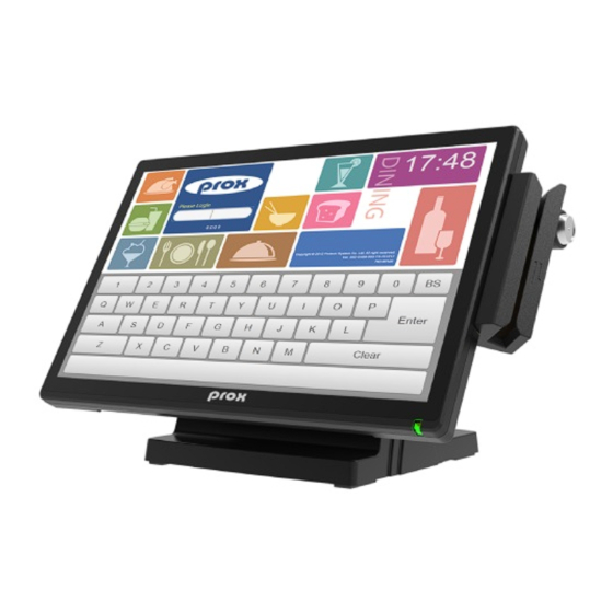
Chapter 1 Introduction System Overview Panel-PC Front View Rear View Left Side Right Side Top View PA-5685 User Manual Page: 1-4... - Page 14 Chapter 1 Introduction Small Stand Front View Rear View Side View Quarter View Adjustable angle 0~70 degrees PA-5685 User Manual Page: 1-5...
- Page 15 Chapter 1 Introduction Big Stand Front View Rear View Side View Quarter View PA-5685 User Manual Page: 1-6...
- Page 16 Chapter 1 Introduction Printer Stand Front View Rear View Side View Quarter View PA-5685 User Manual Page: 1-7...
- Page 17 Chapter 1 Introduction Caution: The correct method of "Closing Printer-Door". Please refer to around drawings. PA-5685 User Manual Page: 1-8...
-
Page 18: System Specifications
1 x 2.5" HDD / SSD maintenance slot DC In 1 x 4-pin DC power jack DC12V Out 1 x 3-pin connector for Protech 2 display 1 x 4-pin connector for Protech Embedded DC 24V Out... - Page 19 15.6" TFT LCD Resolution 1366 x 768 Brightness 220 cd/m² Touchscreen Bezel-Free Projected Capacitive Brightness(cd/m P1 / 167.3 P2 / 195.6 P3 / 189.2 P4 / 158.6 P5 / 191.4 AVR. 180; MIN: 160 PA-5685 User Manual Page: 1-10...
- Page 20 • 8kV air discharge IEC 61000-4-2 • 4kV contact discharge IEC 61000-4-3 80~1000MHz, 3V/m, 80% AM (1kHz) • AC Power Port: 1kV • DC Power Port: 0.5kV IEC 61000-4-4 • Signal Ports & Telecommunication Ports: 0.5kV PA-5685 User Manual Page: 1-11...
- Page 21 0.15~80MHz, 3Vrms, 80% AM, 1kHz IEC 61000-4-6 IEC 61000-4-8 PFMF 50Hz, 1A/m ● > 95% reduction for 0.5 periods Voltage Dips IEC 61000-4-11 ● 30% reduction for 25 periods Voltage Interruptions > 95% reduction for 250 periods PA-5685 User Manual Page: 1-12...
- Page 22 CP-437, Katakana, CP-737, CP-850, CP-852, CP-857, CP-860, CP-862, CP-863,CP-865, CP-866, CP-1250, CP-1251, CP-1252, CP-1253, CP-1254, CP-1255, CP-1257, International Characters USA, FRANCE, GERMANY, UK, DENMARK I, SWDEN, ITALY, SPAIN I, JAPAN, NORWAY, DENMARK II, SPAIN II, LATIN, KOREA, RUSSIA, SLAVONIC PA-5685 User Manual Page: 1-13...
- Page 23 2inch 432 dots; Printable dots per line 3inch 576 dots 2inch 200 mm/s; Maximum print speed 3inch 170 mm/s 2inch 54 mm; Print width 3inch 72mm 2inch 58 +0/-1 mm; Paper width 3inch 80 +0/-1 mm Printer PA-5685 User Manual Page: 1-14...
- Page 24 CP-1251, CP-1252, CP-1253, CP-1254, CP-1257, KANJI • JAPANESE (SHIFT-JIS) Code, TRADITIONAL CHINESE Code International Characters • USA, FRANCE, GERMANY, UK, DENMARK I, SWDEN, ITALY, SPAIN I, JAPAN, NORWAY, DENMARK II, SPAIN II, LATIN AMERICA, KOREA, RUSSIA, SLAVONIC PA-5685 User Manual Page: 1-15...
-
Page 25: Safety Precautions
Avoid direct sunlight exposure for a long period of time (for example, in a closed car in summer time. Also avoid the system from any heating device.). Or do not use PA-5685 when it has been left outdoors in a cold winter day. •... -
Page 26: System Configuration
System Configuration This chapter provides the information for the PA-5685 system. It describes the jumper and connector settings, component locations, and pin assignment. The following topics are included: • External I/O Port Pin Assignment • Mainboard Component Locations & Jumper Setting •... -
Page 27: System External I/O Port & Pin Assignment
System External I/O Port & Pin Assignment Rear I/O COM4 COM3 option HDMI VGA DC-IN LINE COM1 COM2 option 2.5" DC12V DC24V RJ45 RJ11 Storage Only for Prox -display Only for Prox DRW1-1 Printer-Stand option option option Side I/O PA-5685 User Manual Page: 2-2... -
Page 28: Mainboard Component Locations & Jumper Setting
JI2C1 JVOUT_24V JBAT1 JPWR_SW JP19 SATA1 JEM_LED2 Super JP_COM4 JHDD_PWR1 JP16 JP_COM2 JP3 JP_COM3 HDMI JUSB3 JP17 JCOM4_1 JP23 DC-IN DRW1 COM3 COM2 COM1 JCOM3_1 JCOM2_1 COM 2 HDMI COM 3 COM 1 DC IN PA-5685 User Manual Page: 2-3... -
Page 29: How To Set Jumpers
PIN1 and PIN2 to create one setting and shorting. You can also select to connect PIN2 and PIN3 to create another setting. The same jumper diagrams are applied all through this manual. The figure below shows what the manual diagrams look and what they represent. PA-5685 User Manual Page: 2-4... - Page 30 Chapter 2 System Configuration Jumper diagrams Jumper settings PA-5685 User Manual Page: 2-5...
-
Page 31: Setting Connectors And Jumpers
Description: To turn on the system, press the power button on the side of the system briefly. ACTION ASSIGNMENT Click Release +3.3V Power Switch 2.4.2 VGA Port Connector Location: VGA Description: VGA Port, D-Sub 15-pin. ASSIGNMENT ASSIGNMENT GREEN BLUE DDCA DATA HSYNC VSYNC DDCA CLK PA-5685 User Manual Page: 2-6... -
Page 32: Hdmi Port
Description: HDMI Port ASSIGNMENT ASSIGNMENT HDMI_P2 HDMI_N2 HDMI_P1 HDMI_N1 HDMI_P0 HDMI_N0 HDMI_CLKP HDMI_CLKN HDMI HDMI_SCL HDMI_SDA VCC5_HDMI HDMI_HPD 2.4.4 DC IN Port Connector Location: DC IN Description: DC Power-In Port. ASSIGNMENT ASSIGNMENT +24V +24V DC IN PA-5685 User Manual Page: 2-7... -
Page 33: 2Nd Display Power Port
Description: DRW1 is used by default. If you need a second port, adopt the method below. ASSIGNMENT ASSIGNMENT 12V/24V (Max. current DRW2 Sense GPIO1 / DRW1 GPIO2 / DRW2 DRW1 Sense DRW1 Please refer to detail of DRW port.(ex: Page 2-16~Page.2-18) PA-5685 User Manual Page: 2-8... -
Page 34: Com Port
Description: COM Port, D-sub 9-pin . ASSIGNMENT ASSIGNMENT COM1 RI / +5V / +12V selectable (Maximum current: 1A) COM1 Voltage Adjust Voltage of external ports "COM1" is made to control on BIOS for your convenience PA-5685 User Manual Page: 2-9... - Page 35 Chapter 2 System Configuration COM2, COM3, COM4 Voltage Selection Connector Location: JP_COM2, JP_COM3, JP_COM4 Description: Voltage of COM2, COM3 and COM4 ports are controlled by jumpers on board. SELECTION JUMPER SETTING JUMPER ILLUSTRATION JP_COM2 JP_COM3 +12V JP_COM4 PA-5685 User Manual Page: 2-10...
-
Page 36: Com Ports
COM3_1 / COM4_2 (option) 2.4.10 USB Port Connector Location: USB2.0, USB3.0 Description: USB Type A Ports. USB2.0 ASSIGNMENT ASSIGNMENT +5V (Max. current: 0.5A) USB2.0 USB3.0 ASSIGNMENT ASSIGNMENT VCC5 BP_RX_DP USBP4N USBP4P BP_TX_DN BP_TX_DP USB3.0 BP_RX_DN PA-5685 User Manual Page: 2-11... -
Page 37: Lan Port
MDIP1 MDIP3 MDIN1 MDIN3 LAN LED Indicator: Left Side LED Orange Color Blinking Giga LAN Message Active Green Color Blinking 10/100Mbps LAN Message Active Right Side LED Green Color On LAN switch / hub connected. PA-5685 User Manual Page: 2-12... -
Page 38: Com Connectors
Enables COM4 Ports Jumper Location: JP4, JP5, JP6, JP23 Description: Enables COM4 Port JP4 / JP5 / JP6 SELECTION JUMPER SETTING JUMPER ILLUSTRATION COM4 JP4 / JP5 /JP6 JP23 SELECTION JUMPER SETTING JUMPER ILLUSTRATION COM4 JP23 PA-5685 User Manual Page: 2-13... -
Page 39: Spi(Bios) Flash Wafer
ASSIGNMENT +3.3VSB SPI_CS0_N SPI_CLK JP13 SPI_MISO SPI_MOSI 2.4.15 Audio Jack Connector Location: Line Out, Microphone Description: Audio Jack Line Out Microphone Phone Jack 3.5 apply to Phone Jack 3.5 apply to Connector as: Connector as: PA-5685 User Manual Page: 2-14... -
Page 40: Drw Ports
Step 3: DRW1, DRW1-1, DRW1-2 shares the same power RJ11 source. JP16 DRW1-1 JUMPER JUMPER SELECTION SETTING ILLUSTRATION SIO address Cash 1 0xA02 bit5 Status 1 0xA02 bit43 Cash 2 0xA02 bit7 Status 2 0xA02 bit6 PA-5685 User Manual Page: 2-15... - Page 41 To exit the Extended Function Mode, writing 0xAA to the EFER is required. Once the chip exits the Extended Function Mode, it is in the normal running mode and is ready to enter the configuration mode. PA-5685 User Manual Page: 2-16...
- Page 42 Code example for open the cash drawer 1 ;------------------------------ Enter to extended function mode ---------------------------- ; ------------------------ Select Logical Device 6 of Cash drawer ------------------------ ; ------------------------------ Open the Cash drawer 1 ------------------------------------- 0DFh ; ------------------------------Exit the extended function mode ---------------------------- 0aah PA-5685 User Manual Page: 2-17...
- Page 43 Chapter 2 System Configuration DRW2 Connector Location: DRW2 Description: DRW2 Port (Only support PA-5685 selected "Printer kit"). Signal from printer board (MB-1030, MB-1011(3), PDAC3100) and be controlled by command. DRW2 port on the bottom of Stand with a cable (optional).
-
Page 44: Usb Connectors
3. JUSB3 signal is co-lay with "upper port of USB2.0 connector". USB5_1, USB6, USB7 ASSIGNMENT 5V (Maximum current: 0.5A) JUSB3 / JUSB6 / JUSB7 / JUSB8 JUSB4 ASSIGNMENT Vbus JUSB4 JUSB910 ASSIGNMENT ASSIGNMENT + VSB +5VSB SB2_P9_DN USB2_P10_DN SB2_P9_DP USB2_P10_DP JUSB910 PA-5685 User Manual Page: 2-19... -
Page 45: Enable To Jusb8
Description: Enable to Jusb8 SELECTION JUMPER ILLUSTRATION JUSB8 JP18 JP14 2.4.19 Selection of USB2.0 & M.2_E Jumper Location: JP20, JP15 Description: Selection of USB4 & M.2_E SELECTION JUMPER ILLUSTRATION JUSB4 JP20 JP15 M.2_E JP20 JP15 PA-5685 User Manual Page: 2-20... -
Page 46: Power Connector
VCC12 JVOUT_12V 2.4.21 Power for Thermal Printer Connector Connector Location: JVOUT_24V Description: Power for Thermal Printer Connector ASSIGNMENT VCC24 VCC24 JVOUT_24V 2.4.22 Fan Connector Connector Location: CPU_FAN1 Description: Fan Connector ASSIGNMENT VCC12 CPU_FANOUT CPU_FANIN CPU_FAN1 PA-5685 User Manual Page: 2-21... -
Page 47: I-Button Connector
Description: Audio Codec Line Out / MIC Pin Header ASSIGNMENT ASSIGNMENT MIC1-L MIC1-R HD_GND SLP_S3_N JAUDIO1 Jack_Sense DC_VOL_MCU_OUT HD_GND HD_GND LINE-OUT-L LINE-OUT-R 2.4.25 Speaker Connector Connector Location: JSPK1 Description: Speaker Connector ASSIGNMENT HD_FRONT-OUT-R HD_FRONT-OUT-L JSPK1 PA-5685 User Manual Page: 2-22... -
Page 48: Power Indication Led Connector
Connector Location: JSYS_LED1 Description: Power indication LED connector ASSIGNMENT VCC5 JSYS_LED1 2.4.27 Power Switch Connector Location: JPWR_SW Description: Power Switch ASSIGNMENT LPC_PWRBTNJ JPWR_SW 2.4.28 System Reset Connector Location: JP19 Description: System Reset ASSIGNMENT PM_SYS_RSTJ_FP JP19 PA-5685 User Manual Page: 2-23... -
Page 49: Rtc Coin Battery Wafer
Description: RTC Coin Battery Wafer ASSIGNMENT in battery +3V JBAT1 2.4.30 Clear RTC Data Selection Connector Jumper Location: JRTC1 Description: Clear RTC Data Selection Connector SELECTION JUMPER SETTING JUMPER ILLUSTRATION Normal JRTC1 Clear CMOS JRTC1 PA-5685 User Manual Page: 2-24... -
Page 50: Clear Cmos Data
CMOS” as illustrated above. After five to six seconds, set the jumper back to “Normal” and power-on the computer. 2.4.32 Unlock the Entire SPI Flash (override descriptor setting) Jumper Location: JP1 Description: Unlock the Entire SPI Flash (override descriptor setting) SELECTION JUMPER SETTING JUMPER ILLUSTRATION Normal OVERRIDE PA-5685 User Manual Page: 2-25... -
Page 51: Sata 3.0 Connector
Chapter 2 System Configuration 2.4.33 SATA 3.0 Connector Connector Location: SATA1 Description: Serial ATA 3.0 Connector ASSIGNMENT ASSIGNMENT SATA1 2.4.34 HDD Power Port Connector Location: JHDD_PWR1 Description: HDD Power Port ASSIGNMENT VCC5 JHDD_PWR1 PA-5685 User Manual Page: 2-26... -
Page 52: Edp Connector
Chapter 2 System Configuration 2.4.35 eDP Connector Connector Location: JEDP1 Description: eDP Connector ASSIGNMENT ASSIGNMENT DCR_ENABLE TX0_D+ SEL _TEST TX0_D- TX1_D+ E P_HPD TX1_D- BL_ENABLE AUX_D+ AUX_D- VCC12 VCC12 PWM_DIM VCC12 VCC12 JEDP1 VCC3_3 VCC3_3 PA-5685 User Manual Page: 2-27... -
Page 53: Vcc Selection For Edp
Chapter 2 System Configuration 2.4.36 VCC Selection for eDP Jumper Location: JP11 Description: VCC Selection for eDP SELECTION JUMPER SETTING JUMPER ILLUSTRATION 1-3、2-4 3.3V JP11 3-5、4-6 (15.6" & 17") JP11 PA-5685 User Manual Page: 2-28... -
Page 54: M-Key
Chapter 2 System Configuration 2.4.37 M.2 M-Key Connector Location: M2_M Description: M.2 M-Key M2_M ASSIGNMENT ASSIGNMENT SATA_TX_N2 VCC3_3 SATA_TX_P2 VCC3_3 VCC3_3 VCC3_3 SATA_RX_P2 VCC3_3 SATA_RX_N2 Note: M.2 M-key slot supports SATAIII only. PA-5685 User Manual Page: 2-29... -
Page 55: E-Key
ASSIGNMENT VCC3_3 CLKOUT_PCIE_P4 USB_4P CLKOUT_PCIE_N4 VCC3_3 USB_4N PERST0 WIFI M2_E_LED1 PCIE_CLKRQ4_N BT WISABLE2 BT M2_E_LED2 PCH_WAKE_N WIFI WISABLE1 PCIE4_8265_TX_DP PCIE4_8265_TX_DN VCC3_3 PCIE4_8265_RX_DP VCC3_3 PCIE4_8265_RX_DN Note: M.2 E key slot supports USB2.0 and PCIe x1 only. PA-5685 User Manual Page: 2-30... -
Page 56: Peripheral Boards Component Location, Pin Define & Jumper
Chapter 2 System Configuration 2.5 Peripheral Boards Component Location, Pin Define & Jumper Setting 2.5.1 Printer Board: PDAC-3100 PDAC-3100 Printer Board Component Locations PA-5685 User Manual Page: 2-31... -
Page 57: Power Supply Connector
Chapter 2 System Configuration 2.5.1.1 Power Supply Connector Connector Location: CN1 Description: Power supply wafer ASSIGNMENT +24V +24V 2.5.1.2 RS-232 Interface Connector Connector Location: CN7 Description: RS-232 interface connector ASSIGNMENT PA-5685 User Manual Page: 2-32... -
Page 58: Auto-Cutter Connector
Auto-cutter motor drive signal 2A-2 Auto-cutter motor drive signal 1B-1 Auto-cutter motor drive signal 1B-2 Auto-cutter motor drive signal 1A-1 Auto-cutter motor drive signal 1A-2 2.5.1.4 USB Connector Connector Location: CN8 Description: USB Connector ASSIGNMENT Vbus PA-5685 User Manual Page: 2-33... -
Page 59: Thermal Head / Motor / Sensor Connector
Thermistor GND Thermistor signal Unused DST2 Head strobe signal DST1 Head strobe signal Head GND Head GND Head GND Head GND Head GND Head GND LATCH Print data latch Head drive power Head drive power PA-5685 User Manual Page: 2-34... - Page 60 Power supply of the out-ofpaper sensor GND of the platen position/ out-of-paper sensor Signal of the platen position sensor Unused Frame GND Frame GND Unused Motor drive signal Motor drive signal Motor drive signal Motor drive signal PA-5685 User Manual Page: 2-35...
-
Page 61: Thermal Assignment Connector
Feed signal RESET Reset signal Status signal Status signal Status signal Status signal Drawer sensor signal Drawer switch signal Drive terminal for the drawer (Vp side) Drive terminal for the drawer GNDdu (GND side) Unused PA-5685 User Manual Page: 2-36... -
Page 62: Printer Board: Mb-1030 Series
Chapter 2 System Configuration 2.5.2 Printer Board: MB-1030 Series CUT_CN1 COM1 9 10 USB_CN1 24V_CN1 PRINT_CN1 MB-1030 Printer Board Component Locations PA-5685 User Manual Page: 2-37... -
Page 63: Power Supply Connector
Power Supply Connector Connector Location: 24V_CN1 Description: Power supply wafer ASSIGNMENT +24V +24V 24V_CN1 2.5.2.2 RS-232 Interface Connector Connector Location: COM1 Description: RS-232 interface connector ASSIGNMENT ASSIGNMENT DTR / RTS DSR / CTS 9 10 COM1 PA-5685 User Manual Page: 2-38... -
Page 64: Thermal Head / Motor / Sensor Connector
Thermistor GND Thermistor signal Unused DST2 Head strobe signal DST1 Head strobe signal Head GND Head GND Head GND Head GND Head GND Head GND LATCH Print data latch Head drive power Head drive power PA-5685 User Manual Page: 2-39... - Page 65 Power supply of the out-of-paper sensor GND of the platen position / out-of-paper sensor Signal of the platen position sensor Unused Frame GND Frame GND Unused Motor drive signal Motor drive signal Motor drive signal Motor drive signal PA-5685 User Manual Page: 2-40...
-
Page 66: Auto-Cutter Connector
Auto-cutter motor drive signal 2B-2 Auto-cutter motor drive signal 2A-1 Auto-cutter motor drive signal 2A-2 Auto-cutter motor drive signal 1B-1 Auto-cutter motor drive signal 1B-2 Auto-cutter motor drive signal 1A-1 Auto-cutter motor drive signal 1A-2 PA-5685 User Manual Page: 2-41... -
Page 67: Paper-Near-End Sensor Connector
ASSIGNMENT FUNCTION Power supply of the near end sensor Signal of the near end sensor GND of the near end sensor 2.5.2.6 USB Interface Connector Connector Location: USB_CN1 Description: USB interface Connector ASSIGNMENT Vbus USB_CN1 PA-5685 User Manual Page: 2-42... -
Page 68: Thermal Assignment Connector
Feed signal RESET Reset signal Status signal Status signal Status signal Status signal Drawer sensor signal Drawer switch signal Drive terminal for the drawer (Vp side) Drive terminal for the drawer GNDdu (GND side) Unused PA-5685 User Manual Page: 2-43... -
Page 69: Printer Board: Mb-1011 & Mb-1013
Chapter 2 System Configuration 2.5.3 Printer Board: MB-1011 & MB-1013 MB-1013 MB-1011 MB-1011 & MB-1030 Printer Board Component Locations PA-5685 User Manual Page: 2-44... -
Page 70: Power Supply Connector
Chapter 2 System Configuration 2.5.3.1 Power Supply Connector Connector Location: CN1 Description: Power supply wafer ASSIGNMENT +24V +24V 2.5.3.2 RS-232 Interface Connector Connector Location: CN7 Description: RS-232 interface connector ASSIGNMENT PA-5685 User Manual Page: 2-45... -
Page 71: Auto-Cutter Connector
Auto-cutter motor drive signal 2A-2 Auto-cutter motor drive signal 1B-1 Auto-cutter motor drive signal 1B-2 Auto-cutter motor drive signal 1A-1 Auto-cutter motor drive signal 1A-2 2.5.3.4 USB Interface Connector Connector Location: CN8 Description: USB interface Connector ASSIGNMENT Vbus PA-5685 User Manual Page: 2-46... -
Page 72: Thermal Head / Motor / Sensor Connector
Thermistor GND Thermistor signal Unused DST2 Head strobe signal Head strobe signal DST1 Head GND Head GND Head GND Head GND Head GND Head GND Print data latch LATCH Head drive power Head drive power PA-5685 User Manual Page: 2-47... - Page 73 Power supply of the out-of-paper sensor GND of the platen position/ out-of-paper sensor Signal of the platen position sensor Unused Frame GND Frame GND Unused Motor drive signal Motor drive signal Motor drive signal Motor drive signal PA-5685 User Manual Page: 2-48...
-
Page 74: Thermal Assignment Connector
Feed signal RESET Reset signal Status signal Status signal Status signal Status signal Drawer sensor signal Drawer switch signal Drive terminal for the drawer (Vp side) Drive terminal for the drawer GNDdu (GND side) Unused PA-5685 User Manual Page: 2-49... -
Page 75: Vfd Board Component Locations & Pin Assignment
MB-4103 & LD720 VFD Board Component Locations Power Switch Selection JP12V: Power Switch Selection SELECTION JUMPER SETTING JUMPER ILLUSTRATION JP12V JP12V RS-232 Serial Interface Connector CN1: RS-232 serial interface wafer ASSIGNMENT ASSIGNMENT +12V / +5V PA-5685 User Manual Page: 2-50... -
Page 76: Msr Board Component Locations & Pin Assignment
Chapter 2 System Configuration MSR Board Component Locations & Pin Assignment ID TECH ID-TECH MSR Board Component Locations Main Connector ASSIGNMENT ASSIGNMENT K-CLK Chassis Ground (Computer connections) P-CLK K-DATA (Keyboard connections) (Computer connections) P-DATA (Keyboard connections) +5V Vcc PA-5685 User Manual Page: 2-51... - Page 77 Chapter 2 System Configuration MB-3012 I_BUTTON1 MB-3012 MSR Board Component Locations Information Button Reader I_BUTTON1: Information button reader ASSIGNMENT I_B1 I_BUTTON1 Output Connector IO1: Output wafer ASSIGNMENT CLK_KB CLK_PC DATA_KB DATA_PC CHASSIS GND RX_MSR TX_MSR USB_D+_R USB_D-_R PA-5685 User Manual Page: 2-52...
-
Page 78: System Cabling
Chapter 2 System Configuration System Cabling Cable_1 27-006-44003111 PCT cable PA-5685 User Manual Page: 2-53... - Page 79 Chapter 2 System Configuration Cable_2 27-006-44007111 Aside USB Cable PA-5685 User Manual Page: 2-54...
- Page 80 Chapter 2 System Configuration Cable_3 27-012-44011111 DC12V Out Cable PA-5685 User Manual Page: 2-55...
- Page 81 Chapter 2 System Configuration Cable_4 27-018-19703071 System Power indicate cable PA-5685 User Manual Page: 2-56...
- Page 82 Chapter 2 System Configuration Cable_5 27-019-44007071 System Power Switch Cable PA-5685 User Manual Page: 2-57...
- Page 83 Chapter 2 System Configuration Cable_6 27-021-28307072 Speaker Cable PA-5685 User Manual Page: 2-58...
- Page 84 Chapter 2 System Configuration Cable_7 27-072-44006111 eDP Cable PA-5685 User Manual Page: 2-59...
- Page 85 Chapter 2 System Configuration Cable_8 27-055-44001031 Audio Short Cable PA-5685 User Manual Page: 2-60...
-
Page 86: Software
This chapter contains helpful information about the driver utilities and BIOS settings for the system. The following topics are included: • Driver Disc • API • API Function • Peripheral Device • BIOS • Configuring WatchDog Timer • Update Procedure • Appendix PA-5685 User Manual Page3-1... -
Page 88: Driver Disc
Intel(R) Network Connections Software V1.0\Driver\Platform\LAN Chip D:\PB-5685 Realtek High Definition Audio driver V1.0\Driver\Platform\Sound Codec installation D:\PB-5685 Intel(R) Serial IO Driver V1.0\Driver\Platform\Serial IO Note: Users must install the driver utilities right after the OS is fully installed. PA-5685 User Manual Page3-3... -
Page 89: Installing Intel Chipset Software Installation Utility
Enter the “Main Chip” folder where the Chipset driver is located Click “Setup.exe” file for driver installation. Follow the on-screen instructions to install the driver. Once the installation is completed, shut down the system and restart PB-5685 for the changes to take effects. PA-5685 User Manual Page3-3... -
Page 90: Intel ® Management Engine Components Installer
Enter the “ME” folder where the driver is located Click “Setup.exe” file for driver installation. Follow the on-screen instructions to install the driver. Once the installation is completed, shut down the system and restart PB-5685 for the changes to take effects. PA-5685 User Manual Page3-4... -
Page 91: Microsoft Hotfix Driver Installation
Click the “windows10.0-kb3211320-x64 and windows10.0-kb3213986- x64 files” file for critical security update. Follow the on-screen instructions to complete the installation Once the installation is completed, shut down the system and restart PB-5685 for the changes to take effects. PA-5685 User Manual Page3-5... -
Page 92: Installing Graphics Driver Utility
Enter the “Graphics” folder where the driver is located Click the “Setup.exe” file for driver installation. Follow the on-screen instructions to complete the installation. Once the installation is completed, shut down the system and restart PB-5685 for the changes to take effects. PA-5685 User Manual Page3-6... -
Page 93: Installing Lan Driver Utility
Once the installation is completed, shut down the system and restart PB-5685 for the changes to take effects. For more details on the installation procedure, refer to the Readme.txt file that you can find on LAN Driver Utility. PA-5685 User Manual Page3-7... -
Page 94: Installing Sound Driver Utility
Open the “Sound Codec” folder where the driver is located. Click the “Setup.exe” file for driver installation. Follow the on-screen instructions to complete the installation. Once the installation is completed, shut down the system and restart PB-5685 for the changes to take effects. PA-5685 User Manual Page3-8... -
Page 95: Installing Intel Serial I/O Driver Utility
Open the “Serial I/O” folder where the driver is located. Click the “Setup.exe” file for driver installation. Follow the on-screen instructions to complete the installation. Once the installation is completed, shut down the system and restart PB-5685 for the changes to take effects. PA-5685 User Manual Page3-9... -
Page 96: Api
Chapter 3 System Configuration 3.2.1 API Package Content You can find the enclosed API Package files in the Protech Manual / Driver CD. Depending on the machine types, the API Package may include the following files: Function DLL Directory Function... -
Page 97: Api Procedure
Text1.text = “cash drawer1 close”„enter text into textbox. End if „========================================= Receive_Status2 = CashDrawerOpen(&H2) If Receive_Status2 = true then Text2.text = “cash drawer2 open” „enter text into textbox. Else Text2.text = “cash drawer2 close”„enter text into textbox. End if „========================================= End sub PA-5685 User Manual Page3-11... - Page 98 (2) Call Function Open cash drawer1 PortAccess.CashDrawerOpen(0x01); //check cash drawer1 status Open cash drawer2 PortAccess.CashDrawerOpen(0x02); //check cash drawer2 status Bool bstatus; bstatus = PortAccess.GetCashDrawerStatus(0x01); bstatus = PortAccess.GetCashDrawerStatus(0x02); //Before get cash drawer status, need to initial cash drawer first PA-5685 User Manual Page3-12...
- Page 99 Declare Function CashDrawerOpen Lib CashDrawer.dll (ByVal num_drawer as short) As Boolean ------------------------------------------------------------------------------------------------------ VB 6 external function: Declare Function CashDrawerOpen Lib "CashDrawer.dll" (ByVal num_drawer As Integer) As Boolean Declare Function GetCashDrawerStatus Lib "CashDrawer.dll" (ByValnum_drawer As Integer) As Boolean Note: VB.net short = integer VB6 PA-5685 User Manual Page3-13...
-
Page 100: Cash Drawer
Tap to open the cash drawer. Cash drawer status will be displayed after OPEN is tapped. • Cash Drawer is closed when the following picture is shown: Cash Drawer Status • Cash Drawer is opened when the following picture is shown: PA-5685 User Manual Page3-14... -
Page 101: Watchdog
Watch Dog Control • START: Tap to start the watchdog timer. Meanwhile, the REFRESH and STOP buttons will be enabled. • STOP: Tap to stop the watchdog timer. • REFRESH: Tap to restart the watchdog timer. PA-5685 User Manual Page3-15... -
Page 102: Api Function
Return: True (1) on success, False (0) on failure Example: Short data; data= GetCashDrawerStatus(0x01); // Get the Cash Drawer1 status if (data) MsgBox(“open1”); // Cash Drawer1 status “Open” Else MsgBox(“close1”); // Cash Drawer1 status “Close” Endif PA-5685 User Manual Page3-16... -
Page 103: Watch Dog Function
Purpose: Stop the watchdog timer. Value None Return: True (1) on success, False (0) on failure Watchdog_Recount bool Watchdog_Recount (void); Purpose: Restart the watchdog timer. Value None Return: True (1) on success, False (0) on failure PA-5685 User Manual Page3-17... -
Page 104: Peripheral Devices
GS h ESC - FS q GS k ESC 2 GS ! GS r ESC 3 GS $ GS v 0 ESC = GS * GS w ESC ? GS ( A ESC @ GS ( K PA-5685 User Manual Page3-18... - Page 105 <ESC -> 1B 2D Turn underline mode on/off. <ESC 2> 1B 32 Select default line spacing <ESC 3> 1B 33 Set line spacing <ESC => 1B 3D Select peripheral device <ESC @> 1B 40 Initialize printer PA-5685 User Manual Page3-19...
- Page 106 1C 70 Print NV bit image Disabled ◎ <FS q> 1C 71 Define NV bit image Disabled <GS !> 1D 21 Select character size Set absolute vertical print Ignored <GS $> 1D 24 position in page mode PA-5685 User Manual Page3-20...
- Page 107 Hexadecimal Standard Page Function Codes Codes Mode Mode Specifies a module size of <DC2 ;> 12 3B QR Code and Data Matrix Prints QRCode data based on <GS p 1> 1D 70 01 the specified contents PA-5685 User Manual Page3-21...
- Page 108 ● : Enabled only when data is not present in the printer buffer. ▲ : Only value setting is possible. Disabled: Parameters are processed as printable data. Ignored: All command codes including parameters are ignored and nothing is executed. PA-5685 User Manual Page3-22...
- Page 109 Decimal 10 [Range] Prints the data in the print buffer and performs a line feed based on the set line feed amount. [Description] • After execution, makes the top of the line the next print starting position. PA-5685 User Manual Page3-23...
- Page 110 Deletes all print data in the currently set print region in page mode. • [Description] This command is enabled only in page mode. • Portions included in the currently set print region are also deleted, even if previously set print region data. PA-5685 User Manual Page3-24...
- Page 111 Not used. Fixed to On. Cover is closed. Cover is open. Not used. Fixed to Off. Not used. Fixed to On. No paper-end stops. Printing stops due to paper end. No error. Error occurs. Not used. Fixed to Off. PA-5685 User Manual Page3-25...
- Page 112 No paper-near-end stops. Printing stops due to paper near end. Not used. Fixed to On. No paper-end stops. Printing stops due to paper end. No paper-end stops. Printing stops due to paper end. Not used. Fixed to Off. PA-5685 User Manual Page3-26...
- Page 113 = 0: #2 Pin of the drawer kick connector m = 1: #5 Pin of the drawer kick connector On time is set to t x 100 msec; Off time is set to t x 100 msec. PA-5685 User Manual Page3-27...
- Page 114 This command specifies the next print starting position in reference to the left edge of the print area. The printing start position is calculated using [Description] (nL + nH x 256) x (vertical or horizontal motion units). Specifications exceeding the print range are ignored. PA-5685 User Manual Page3-28...
- Page 115 Not used. Fixed to Off. Emphasized mode not selected. Emphasized mode selected. [Description] Double-height mode not selected Double-height mode selected Double-width mode not selected. Double-width mode selected. Not used. Fixed to Off. Underline mode not selected. Underline mode selected. PA-5685 User Manual Page3-29...
- Page 116 67 DPI 101 DPI [Description] density 8 dot nL+nH× double 67 DPI 203 DPI density 24 dot (nL+nH× single 203 DPI 101 DPI 256) ×3 density 24 dot (nL+nH× double 203 DPI 203 DPI 256) ×3 density PA-5685 User Manual Page3-30...
- Page 117 Hex. Decimal 51 n 0 ≤ n ≤ 255 [Range] Initial Value n = 34 This command sets the line spacing using a following rule. [Description] Line spacing = n x (vertical or horizontal motion units) PA-5685 User Manual Page3-31...
- Page 118 Sets horizontal tab position • n specifies the column number for setting a horizontal tab [Description position from the left margin or the beginning of the line. • k indicates the number of horizontal tab positions to be set. PA-5685 User Manual Page3-32...
- Page 119 • This printer is not capable of double printing, so the print is the same as when using emphasized printing. • This command is enabled for ANK characters PA-5685 User Manual Page3-33...
- Page 120 ESC T, the horizontal motion unit (x) is used. • The maximum line spacing is 150mm {5.9 inches}. When the setting value exceeds the maximum, it is converted to the maximum automatically. PA-5685 User Manual Page3-34...
- Page 121 The following commands are invalid in page mode. FS p :Print NV bit image FS q :Define NV bit image GS v 0 :Print raster bit images GS L :Set left margin • Recover to standard mode using ESC @ (initialize printer). PA-5685 User Manual Page3-35...
- Page 122 Initial Value n = 0 This command specifies international characters according to n values. Character set France Germany Denmark I Sweden Italy [Description] Spain Japan Norway Denmark II Spain II Latin America Korea Russia Slavonic User Define PA-5685 User Manual Page3-36...
- Page 123 GS $ :Specify absolute position for character vertical direction in page mode GS \: :Specify relative position for character vertical direction in page mode • Standard mode is selected when the power is turned on, the printer is reset or initialized (ESC @). PA-5685 User Manual Page3-37...
- Page 124 Lower Left (B in the figure 1, 49 Bottom to Top below) Lower Right (C in the figure 2, 50 Right to Left below) Upper Right (D in the figure [Description] 3, 51 Top to Bottom below) PA-5685 User Manual Page3-38...
- Page 125 • This command only affects printing in standard mode. • In page mode, this command is only effective for the setting. • This command is effective for ANK and Chinese characters. PA-5685 User Manual Page3-39...
- Page 126 (horizontal printable area - horizontal starting position). • If (vertical starting position + printing area height) exceeds the printable area, the printing area height is automatically set to (vertical printable area- vertical starting position). PA-5685 User Manual Page3-40...
- Page 127 Initial Value n = 0 This command specifies position alignment for all data in one line in standard mode, using n as follows: Alignment Left alignment [Description] Center alignment Right alignment This command has no effect in page mode. PA-5685 User Manual Page3-41...
- Page 128 Selects the paper out detector to stop printing when paper has run out. 〝0〞 〝1〞 Function Undefined Undefined Undefined [Description] Undefined Undefined Undefined Paper roll near end detector Invalid Valid Paper roll near end detector Invalid Valid PA-5685 User Manual Page3-42...
- Page 129 Paper is fed approximately 150 mm if the [n x basic calculated pitch] exceeds approximately 150 mm (5.9 inches). ESC i [Name] Full cut. ASCII [Format] Hex. Decimal 27 105 [Range] This command executes a full cut of the paper in standard [Description] mode PA-5685 User Manual Page3-43...
- Page 130 Drawer kick on time is set to t1 x 2 ms; off time is set to t2 x 2 Connector Pin [Description] 0, 48 Drawer kick connector pin #2 1, 49 Drawer kick connector pin #5 PA-5685 User Manual Page3-44...
- Page 131 • This command has no affect in page mode. In page mode, [Description] this command is only effective for the setting. • Upside-down printing rotates line data 180 degrees. Upside-down mode Turned off Turned on PA-5685 User Manual Page3-45...
- Page 132 NV bit image (xL + xH x 256) x 8 dots. • yL and yH specify the vertical direction for one NV bit image (yL [Description] + yH x 256) x 8 dots. PA-5685 User Manual Page3-46...
- Page 133 Refer to Table 2 times normal font size in [Enlarged in vertical the vertical direction direction] Specifies the number of Refer to Table 1 times normal font size in [Enlarged in horizontal the horizontal direction direction] PA-5685 User Manual Page3-47...
- Page 134 [(nL + nH x 256) x basic calculated pitch] from the starting point. • When not in page mode, this command is ignored. • Specifications for absolute positions that exceed the specified print range are ignored. PA-5685 User Manual Page3-48...
- Page 135 Y x 8 dots • d indicates the bit-image data. Bits that correspond to the dots to print are 1, and the bits that correspond to the dots that are not printed are 0. • [Description] PA-5685 User Manual Page3-49...
- Page 136 [Description] 0 , 48 Basic sheet (paper roll) 1 , 49 Paper Roll 2 , 50 m specifies a test pattern.. Paper Type 2 , 50 Printer Status (Self Print) 3 , 51 Rolling Pattern Print PA-5685 User Manual Page3-50...
- Page 137 This command prints the downloaded bit image defined by GS * according to the mode denoted by m. Vertical dot Horizontal dot Mode density(DPI) density(DPI) [Description] 0 , 48 Normal 1 , 49 Double-width 2 , 50 Double-height 3 , 51 Quadruple PA-5685 User Manual Page3-51...
- Page 138 Selects the printing position of HRI characters when printing bar codes. Printing Position 0 , 48 No print [Description] 1 , 49 Above bar code 2 , 50 Below bar code 3 , 51 Above and below bar code(both) PA-5685 User Manual Page3-52...
- Page 139 MB-1030 System or MP-1060 Name System [Description] Model Name MB-1030 or MP-1060 Serial Number Depends on the serial number Taiwan Language Characters: TW_BIG5 Japanese Language Characters: Chinese JP_SJIS Character Types Chinese Language Characters: CN_GB2312 Korean Language Characters: KO_EUC-KR PA-5685 User Manual Page3-53...
- Page 140 25.4/xmm [(1/x) inch], and the vertical basic calculated pitch to approximately 25.4/ymm [(1/y) inch]. x = 0: Returns the horizontal basic calculated pitch to its [Description] default value. y = 0: Returns the vertical basic calculated pitch to its default value. PA-5685 User Manual Page3-54...
- Page 141 Sets the print region width specified by nL and nH. • Print region width is [(nL + nH x 256) x basic calculated pitch]. • [(nL + nH x 256) x basic calculated pitch] >=24. [Description] PA-5685 User Manual Page3-55...
- Page 142 (ASB: Automatic Status Back). “0” “1” Bits Statuses Targeted for ASB Undefined Undefined Undefined Undefined Continuous Paper Detector Invalid Valid Error Invalid Valid ONLINE/OFFLINE Status Invalid Valid Drawer kick connector pin #3 Invalid Valid PA-5685 User Manual Page3-56...
- Page 143 Not used. Fixed to Off Not used. Fixed to Off Not used. Fixed to Off Not used. Fixed to Off Not used. Fixed to Off Not used. Fixed to Off Not used. Fixed to Off Not used. Fixed to Off PA-5685 User Manual Page3-57...
- Page 144 = 0,1,48,49 [Range] Initial Value n = 0 Selects the HRI character font when printing bar codes. Font [Description] 0 , 48 Selects Font A (12 x 24). 1 , 49 Selects Font B (9 x 17). PA-5685 User Manual Page3-58...
- Page 145 2 ≤ k ≤ 254 48 ≤ d ≤ 57 (However, This is an even number.) 48 ≤ d ≤ 57, 65 ≤ d ≤ 68, 1 ≤ k ≤ 255 CODABAR 36, 43, 45, 46, 47, PA-5685 User Manual Page3-59...
- Page 146 48 ≤ d ≤ 57, 65 ≤ d ≤ 68, 1 ≤ n ≤ 255 CODABAR 36, 43, 45, 46, 47, 1 ≤ n ≤ 255 0 ≤ d ≤ 127 CODE93 2 ≤ n ≤ 255 0 ≤ d ≤ 127 CODE128 PA-5685 User Manual Page3-60...
- Page 147 Paper roll near end detector Has Paper Paper out [Description] Drawer Kick Connector Status (n=2,50) “0” “1” Bits Status Fixed at 0 Undefined Undefined Fixed at 0 Undefined Undefined Undefined 〝 L 〞 〝 H 〞 Drawer kick connector pin #3 PA-5685 User Manual Page3-61...
- Page 148 (xL + xH x 256) in bytes. • yL and yH specify the vertical direction data count for one bit image (yL + yH x 256) in bytes. [Description] PA-5685 User Manual Page3-62...
- Page 149 Hex. Decimal 2 ≤ n ≤ 16 [Range] Initial Value n = 2 Specifies a module size of QR Code and Data Matrix. [Description] n: The number of dots for one side of the module size. PA-5685 User Manual Page3-63...
- Page 150 Mode Hexadecimal Mode [Description] Numerical mode Alphanumeric mode 8-bit byte mode Kanji mode Mixed mode nl, nh: Specifies the number of data. Data: Kanji data of the QRCode data should be set by Shift JIS code. PA-5685 User Manual Page3-64...
- Page 151 Undefined FS & [Name] Select Kanji character mode. ASCII & [Format] Hex. Decimal [Range] [Description] Specifies Kanji character mode. FS . [Name] Cancel Kanji character mode. ASCII [Format] Hex. Decimal [Range] [Description] Cancels Kanji character mode. PA-5685 User Manual Page3-65...
- Page 152 Initial Value n = 0 Specifies or cancels quadruple size Kanji character. • Cancels quadruple size when n = <*******0>B. [Description] • Specifies quadruple size when n = <*******1>B. • n is effective only when it is the lowest bit. PA-5685 User Manual Page3-66...
-
Page 153: Opos Printer Driver
Follow the wizard instructions to complete the installation. Launching the Program Below steps guide you to load the MB1030 program. • Click POSPrinter folder from the path Start\Programs\Protech OPOS. • Click MB1030 to launch the program. PA-5685 User Manual Page3-67... - Page 154 Chapter 3 System Configuration OPOS Control Object of MB1030 Program Print tab buttons: Button/Item Description Printer Normal Print the string. Bitmap tab buttons/items: Button/Item Description Load Load bitmap file. Print Bitmap Print bitmap file. Type Normal or Rotate 108°. PA-5685 User Manual Page3-68...
- Page 155 Key Name Type Default Value Note BaudRate String 115200 UART Baud Rate (default) BitLength String UART Data Bit (default) Parity String UART Parity Bit (default) Port String COM4 UART Port (default) Stop String UART Stop Bit (default) PA-5685 User Manual Page3-69...
- Page 156 Read only Not Applicable Properties specific bool CapJrnBold Read only Not Applicable Properties specific long CapJrnCartridgeSensor Read only Not Applicable Properties specific long CapJrnColor Read only Not Applicable Properties specific long CapJrnDhigh Read only Not Applicable PA-5685 User Manual Page3-70...
- Page 157 Read only Not Applicable Properties specific bool CapSlpDhigh Read only Not Applicable Properties specific bool CapSlpDwide Read only Not Applicable Properties specific bool CapSlpDwideDhigh Read only Not Applicable Properties specific bool CapSlpEmptySensor Read only Not Applicable PA-5685 User Manual Page3-71...
- Page 158 Read only Not Applicable Properties specific bool RecNearEnd Read only Not Applicable Properties specific long RecSidewaysMaxLines Read only Not Applicable Properties specific long RecSidewaysMaxChars Read only Not Applicable Properties specific long RecLinesToPaperCut Read only Not Applicable PA-5685 User Manual Page3-72...
- Page 159 PrintNormal Supported Methods specific PrintTwoNormal Not Applicable Methods specific PrintImmediate Not Applicable Methods specific BeginInsertion Not Applicable Methods specific EndInsertion Not Applicable Methods specific BeginRemoval Not Applicable Methods specific EndRemoval Not Applicable Methods specific CutPaper Supported PA-5685 User Manual Page3-73...
- Page 160 ChangePrintSide Not Applicable Methods specific MarkFeed Not Applicable Events common DataEvent Not Applicable Events common DirectIOEvent Not Applicable Events common ErrorEvent Not Applicable OutputComplete Event Events common Not Applicable Events common StatusUpdate Event Not Applicable PA-5685 User Manual Page3-74...
-
Page 161: Vfd: Mb-4103 (Rs-232)
BitLength Parity Port COM1 Stop 2. OPOS VFD Service Object and Method Relations Method Status of support Notes ○ Open ○ Close ○ ClaimDevice ○ ReleaseDevice ○ Enable ○ Disable ○ DisplayText ○ DisplayTextAt ○ ClearText PA-5685 User Manual Page3-75... -
Page 162: Opos Driver
Follow the wizard instructions to complete the installation. Launching the Program Below steps guide you to load the Prox-PMP4000 program. • Click LineDisplay folder from the path Start/Programs/Protech OPOS. • Click Prox-PMP4000 to launch the program. PA-5685 User Manual Page3-76... - Page 163 Key Name Type Default Value Note UART Baud Rate (default) BaudRate String 9600 UART Data Bit (default) BitLength String UART Parity Bit (default) Parity String UART Port (default) Port String COM1 UART Stop Bit (default) Stop String PA-5685 User Manual Page3-77...
- Page 164 Read only Not Applicable Properties specific bool CapICharWait Read only Not Applicable Properties specific long CapReadBack Read only Not Applicable Properties specific long CapReverse Read only Not Applicable Properties specific bool CapVMarquee Read only Not Applicable PA-5685 User Manual Page3-78...
- Page 165 DisplayText Supported Methods specific DisplayTextAt Supported Methods specific ClearText Supported Methods specific ScrollText Not Applicable Methods specific SetDescriptor Not Applicable Methods specific ClearDescriptors Not Applicable Methods specific CreateWindow Not Applicable Methods specific DestroyWindow Not Applicable PA-5685 User Manual Page3-79...
- Page 166 ReadCharacterAtCursor Not Applicable Methods specific DefineGlyph Not Applicable Events common DataEvent Not Applicable Events common DirectIOEvent Not Applicable Events common ErrorEvent Not Applicable Events common OutputComplete Event Not Applicable StatusUpdate Event Events common Not Applicable PA-5685 User Manual Page3-80...
-
Page 167: Msr: Mb-3012 (Ps/2)
Follow the wizard instructions to complete the installation. Launching the Program Below steps guide you to load the Prox-PMP3000 program. • Click MSR folder from the path Start/Programs/Protech OPOS. • Click Prox-PMP3000 to launch the program. PA-5685 User Manual Page3-81... - Page 168 Configuration of Prox-PMP3000 program Main screen & Control tab items: Button/Item Description (dropdown list) To set COM port number (only for USRT / USB interface). AutoDisable (check box) Set auto-disable FreeseEvents (check box) Set freeze events PA-5685 User Manual Page3-82...
- Page 169 Set decode data properties applicable). ParseDecodeData Set parse decode data properties TransmitSentinels Set transmit-sentinels properties ErrorReporting Type Card, track Track1, track2, track3, tracks12, tracks13, tracks14, tracks23, tracks24, tracks34, tracks123, TracksToRead tracks124, tracks134, tracks234, tracks1234 (Tracks4 is not applicable). PA-5685 User Manual Page3-83...
- Page 170 Chapter 3 System Configuration Track Data tab items Button/Item Description TracksData (Row) Display data of all tracks (Track4 is not applicable). Parsed Data tab items Button/Item Description Parsed Data Display special properties. PA-5685 User Manual Page3-84...
- Page 171 CapJISOne Read only Supported Properties specific bool CapJISTwo Read only Supported Properties specific bool CapTransmitSentinels Read only Supported Properties specific long TracksToRead Supported Properties specific bool DecodeData Not Applicable Properties specific bool ParseDecodeData Supported PA-5685 User Manual Page3-85...
- Page 172 ClearInput Supported Methods common ClearOutput Not Applicable Methods common DirectIO Not Applicable Events common DataEvent Supported Events common DirectIOEvent Not Applicable Events common ErrorEvent Not Applicable Events common OutputCompleteEvent Not Applicable Events common StatusUpdateEvent Not Applicable PA-5685 User Manual Page3-86...
-
Page 173: Msr: Giga-Tms Mjr243R (Rs-232)
MSR POS DeviceName MJR243 Devive Name for CO open FileName (NULL) (reserved) HardwareProvider (reserved) Model MJR243 Device model name Parity None Parity for the communication port Port COM4 Comport Protocol Hardware Communication Control Baudrate 19200 RS232 baudrate PA-5685 User Manual Page3-87... - Page 174 ○ CapTransmitSentinels Read only ○ AccountNumber Read only ○ DecodeData ○ ExpirationDate Read only ○ FirstName Read only ○ MiddleInitial Read Only ○ ParseDecodeData ○ ServiceCode Read Only ○ Suffix Read Only ○ Surname Read Only PA-5685 User Manual Page3-88...
- Page 175 Chapter 3 System Configuration Method Status of support Notes ○ Title Read Only ○ Track1Data Read Only ○ Track1DiscretionaryData Read Only ○ Track2Data Read Only ○ Track2DiscretionaryData Read Only ○ Track3Data Read Only ○ TracksToRead ○ TransmitSentinels PA-5685 User Manual Page3-89...
-
Page 176: Opos Msr Register
Follow the wizard instructions to complete the installation. Launching the Program Below steps guide you to load the OPOS MSR Register program. • Click OPOS folder from the path Start/Programs/GIGA‐TMS. • Click OPOS MSR Register to launch the program. PA-5685 User Manual Page3-90... - Page 177 Step 1: Select an item in Service Object List box (left pane).Make sure the correct item is selected. Step 2: Click Reg→ button Step 3: In the OPOS MSR Setting screen, enter the device name and click PA-5685 User Manual Page3-91...
- Page 178 Chapter 3 System Configuration Example 1. MAGTEK USB HID d. Example 2. PROMAG MSR/MJR PART‐ NO, Keyboard mode. PA-5685 User Manual Page3-92...
- Page 179 Enable the tracing, and create Debug string a log file GIGATMS Description string Description for SO driver MSR POS DeviceName string MJR243 Devive Name for CO open FileName string (NULL) (reserved) HardwareProvider string (reserved) Model string MJR243 Device model name PA-5685 User Manual Page3-93...
- Page 180 Properties common long ControlObjectVersion Read only Supported Properties common string ServiceObject Description Read only Supported Properties common long ServiceObjectVersion Read only Supported Properties common string DeviceDescription Read only Supported Properties common string DeviceName Read only Supported PA-5685 User Manual Page3-94...
- Page 181 Properties specific bool TransmitSentinels Supported Methods Open Supported common Methods common Close Supported Methods common Claim Supported Methods common ClaimDevice Supported Methods common Release Supported Methods common ReleaseDevice Supported Methods common CheckHealth Not Applicable Methods ClearInput Supported common PA-5685 User Manual Page3-95...
- Page 182 Not Applicable Methods UpdateFirmware Not Applicable common Methods common UpdateStatistics Not Applicable Events common DataEvent Supported Events common DirectIOEvent Not Applicable Events common ErrorEvent Not Applicable Events common OutputCompleteEvent Not Applicable Events common StatusUpdateEvent Not Applicable PA-5685 User Manual Page3-96...
-
Page 183: Opos Msr Tester
The installation of OPOS MSR Tester program goes together with OPOS MSR Register program. Launching the Program Below steps guide you to load the OPOS MSR Tester program. • ‐ Click OPOS folder from the path Start\Programs\GIGA TMS. • Click OPOS MSR Tester to launch the program PA-5685 User Manual Page3-97... - Page 184 (Text box) Display the result message of running the Message OPOS driver. To start using OPOS driver to get track data, follow the steps below. Step 1: Entering the Device Name. Step 2: Clicking Open button. Step 3: Swiping card to get track data. PA-5685 User Manual Page3-98...
- Page 185 Chapter 3 System Configuration Example 1. MAGTEK USB HID Example 2. PROMAG MSR/MJR PART‐ NO, Keyboard mode PA-5685 User Manual Page3-99...
- Page 186 Chapter 3 System Configuration Example 3. PROMAG MSR PART‐ NO, HID mode PA-5685 User Manual Page3-100...
-
Page 187: Bios
3.5.1 BIOS Setup The board PA-5685 uses an AMI Aptio BIOS that is stored in the Serial Peripheral Interface Flash Memory (SPI Flash) and can be updated. The SPI Flash contains the BIOS Setup program, Power-on Self-Test (POST), the PCI auto-configuration utility, LAN EEPROM information, and Plug and Play support. - Page 188 3. The system configuration is reset after the user configures to clear CMOS data via the JCMOS1 jumper. 4. The power of the CMOS RAM became lost and the system configuration has been erased. All the menu settings are described in details in this chapter. PA-5685 User Manual Page3-102...
-
Page 189: Accessing Setup Utility
Setup program. In a moment, the main menu of the Aptio Setup Utility will appear on the screen: BIOS Setup Menu Initialization Screen PA-5685 User Manual Page3-103... - Page 190 Execute the command or select the sub-menu. <F2> Load the previous configuration values. <F3> Load the default configuration values. <F4> Save the current values and exit the BIOS setup menu. Close the sub-menu. <Esc> Trigger the confirmation to exit BIOS setup menu. PA-5685 User Manual Page3-104...
-
Page 191: Main
The “Day” is automatically changed. Set the clock of the system. The format is [Hour: Minute: Second]. Users can directly System Time hour, minute, second enter values or use <+> or <-> arrow keys to increase/decrease it. PA-5685 User Manual Page3-105... -
Page 192: Advanced
Sub-Menu Management Engine Technology PCH-FW Configuration Sub-Menu Parameters. Trusted Computing Trusted Computing Settings. Sub-Menu ACPI Settings System ACPI Parameters. Sub-Menu F81866 Super IO System Super IO Chip parameters. Sub-Menu Configuration Hardware Monitor Monitor hardware status Sub-Menu PA-5685 User Manual Page3-106... -
Page 193: Advanced - Cpu Configuration
No changeable options Displays the CPU ID. Microcode No changeable options Displays the CPU Microcode Revision. Revision Speed No changeable options Displays the CPU Speed. Number of No changeable options Displays the CPU Number of Processors. PA-5685 User Manual Page3-107... - Page 194 - Disabled When Disabled, only one thread per Hyper-threading - Enabled enabled core is enabled. Intel (VMX) When enabled, VMM can utilize the - Disabled Virtualization additional hardware capabilities provided - Enabled Technology by Vanderpool Technology PA-5685 User Manual Page3-108...
-
Page 195: Advanced - Sata Configuration
Displays the SATA device‟s name. No changeable options Indicates whether the connected SATA Software Preserve No changeable options device supports Software Setting Preservation (SSP). - Disabled Port 0 - 1 Enables or Disables SATA Port Device. - Enabled PA-5685 User Manual Page3-109... -
Page 196: Advanced - Pch-Fw Configuration
BIOS Setting Options Description/Purpose ME Firmware Version No changeable options Displays the ME Firmware Version. ME Firmware Mode No changeable options Displays the ME Firmware Mode. ME Firmware SKU No changeable options Displays the ME Firmware SKU. PA-5685 User Manual Page3-110... -
Page 197: Advanced - Trusted Computing
State of the Device. Schedules an Operation for the Security Device. - None Pending operation NOTE: Your Computer will reboot - TPM Clear during restart in order to change State of Security Device. PA-5685 User Manual Page3-111... - Page 198 TPM 1.2 devices will be enumerated. TPM Enabled Status No changeable options Displays the TPM Enabled Status. TPM Active Status No changeable options Displays the TPM Active Status. TPM Owner Status No changeable options Displays the TPM Owner Status. PA-5685 User Manual Page3-112...
-
Page 199: Advanced - Acpi Settings
SUSPEND - S3 (Suspend to RAM) button is pressed. Lock Legacy - Disabled Enables or Disables Lock of Legacy Resources - Enabled Resources. - Disabled S3 Video Repost Enables or Disables S3 Video Repost. - Enabled PA-5685 User Manual Page3-113... -
Page 200: Advanced - F81866 Super Io Configuration
Configure the parameters of Serial Port 4 Serial Port 4 Configuration Sub-menu (COMD). Configure the parameters of Serial Port 5 Serial Port 5 Configuration Sub-menu (COME). Configure the parameters of Serial Port 6 Serial Port 6 Configuration Sub-menu (COMF). PA-5685 User Manual Page3-114... - Page 201 Select IRQ and I/O resource Change Settings - IO=2F8h; IRQ=3,4,5,6,7,10,11; settings for Serial Port 1. - IO=3E8h; IRQ=3,4,5,6,7,10,11; - IO=2E8h; IRQ=3,4,5,6,7,10,11; - RI Disable or select 12V / 5V Mode - 5V voltage for COM1. - 12V PA-5685 User Manual Page3-115...
- Page 202 Device Settings No changeable options Serial Port 2. -Auto - IO=2F8h; IRQ=3; - IO=3F8h; IRQ=3,4,5,6,7,10,11; Select IRQ and I/O resource for Change settings - IO=2F8h; IRQ=3,4,5,6,7,10,11; the serial port 2. - IO=3E8h; IRQ=3,4,5,6,7,10,11; - IO=2E8h; IRQ=3,4,5,6,7,10,11; PA-5685 User Manual Page3-116...
- Page 203 Device Settings No changeable options Serial Port 3. - Auto - IO=3E8h; IRQ=7; - IO=3E8h; IRQ=3,4,5,6,7,10,11; Select IRQ and I/O resource for Change settings - IO=2E8h; IRQ=3,4,5,6,7,10,11; the serial port 3. - IO=2F0h; IRQ=3,4,5,6,7,10,11; - IO=2E0h; IRQ=3,4,5,6,7,10,11; PA-5685 User Manual Page3-117...
- Page 204 Device Settings No changeable options Serial Port 4. - Auto - IO=2E8h; IRQ=6; - IO=3E8h; IRQ=3,4,5,6,7,10,11; Select IRQ and I/O resource for Change settings - IO=2E8h; IRQ=3,4,5,6,7,10,11; the serial port 4. - IO=2F0h; IRQ=3,4,5,6,7,10,11; - IO=2E0h; IRQ=3,4,5,6,7,10,11; PA-5685 User Manual Page3-118...
- Page 205 Device Settings No changeable options Serial Port 5. - Auto - IO=2F0h; IRQ=10; - IO=3E8h; IRQ=3,4,5,6,7,10,11; Select IRQ and I/O resource for Change settings - IO=2E8h; IRQ=3,4,5,6,7,10,11; the serial port 5. - IO=2F0h; IRQ=3,4,5,6,7,10,11; - IO=2E0h; IRQ=3,4,5,6,7,10,11; PA-5685 User Manual Page3-119...
- Page 206 Device Settings No changeable options Serial Port 6. - Auto - IO=2E0h; IRQ=11; - IO=3E8h; IRQ=3,4,5,6,7,10,11; Select IRQ and I/O resource for Change settings - IO=2E8h; IRQ=3,4,5,6,7,10,11; the serial port 6. - IO=2F0h; IRQ=3,4,5,6,7,10,11; - IO=2E0h; IRQ=3,4,5,6,7,10,11; PA-5685 User Manual Page3-120...
-
Page 207: Advanced - Hardware Monitor
VSB5V in supply. Displays the voltage level of VCC5 in VCC5V No changeable options supply. Displays the voltage level of VCC12 in VCC12 No changeable options supply. VCC3V No changeable options Displays the voltage level of VCC3V in PA-5685 User Manual Page3-121... - Page 208 - Manual Duty Mode Smart Fan Mode select for CPU Fan. Control - Auto Duty-Cycle Mode Manual mode fan control, user can Manual Duty Mode Numeric (from 1 to 100) write expected duty cycle (PWM fan type) 1-100. PA-5685 User Manual Page3-122...
-
Page 209: Advanced - F81866 Watchdog
Enable/ Disable F81866 Watchdog timer. - Disable - 1s Watchdog timer unit Select seconds or minutes - 60s Count for Timer multiple options Sets the desired value (in seconds) for (Seconds) ranging from 1 to 255 watchdog timer. PA-5685 User Manual Page3-123... -
Page 210: Advanced - Usb Configuration
The USB Configuration allows users to configure advanced USB settings such as USB mass storage driver support. USB Configuration Screen BIOS Setting Options Description/Purpose Legacy USB - Disabled Enables support for legacy USB. Support - Enabled PA-5685 User Manual Page3-124... -
Page 211: Advanced - Network Stack Configuration
Number of seconds to wait for PXE boot PXE boot wait time (from 0 to 5) to abort after the Esc key is pressed. Numeric Number of times that the media presence Media detect count (from 1 to 50) will be checked. PA-5685 User Manual Page3-125... -
Page 212: Chipset
System Agent (SA) and PCH-IO configuration parameters. Chipset Menu Screen BIOS Setting Options Description/Purpose System Agent (SA) Sets the Parameter for System Agent (SA) Sub-menu Parameters configuration. PCH-IO Configuration Sub-menu Sets the Parameter for PCH configuration. PA-5685 User Manual Page3-126... -
Page 213: System Agent (Sa) Configuration
Options Description/Purpose SA PCIe Code No changeable options Displays the SA PCIe Code Version. Version VT-d No changeable options VT-d capability. Memory Sub-menu Memory Configuration Configuration - Disabled VT-d Enables or Disables VT-d function. - Enabled PA-5685 User Manual Page3-127... - Page 214 Memory Timings No changeable options Displays the Memory Timings. (tCL-tRCD-tRP-tRAS) Displays the Channel 0 Slot 0 Channel 0 Slot 0 No changeable options Subtitle. size No changeable options Displays the size of Channel 0 Slot 0. PA-5685 User Manual Page3-128...
-
Page 215: Pch Io Configuration
- Enabled wake the system. Specifies the Power On/Off state that - Power On the system will go to when the power is State After G3 - Power Off re-applied following a power failure (G3 state). PA-5685 User Manual Page3-129... - Page 216 PCH-IO Configuration – PCI Express Configuration Menu Path Chipset > PCH-IO Configuration > PCI Express Configuration PCI Express Configuration Screen BIOS Setting Options Description/Purpose PCIE Port assigned to Displays the LAN assigned PCIE No changeable options Port. PA-5685 User Manual Page3-130...
-
Page 217: Security
Setup utility. Security Menu Screen BIOS Setting Options Description/Purpose Administrator Password can be 3-20 Specifies the administrator password. Password alphanumeric characters. Password can be 3-20 User Password Specifies the user password. alphanumeric characters. PA-5685 User Manual Page3-131... - Page 218 Security menu and press <Enter>, and the password dialog entry box appears. 2. Select the configured Administrator Password or User Password that you want to delete. Leave the dialog box blank and press <Enter>. 3. Press <Enter> again when the password confirmation box appears. PA-5685 User Manual Page3-132...
-
Page 219: Boot
Quiet Boot - Enabled - Disabled Enables/Disables Fast Boot Options Fast Boot - Enabled Allows users to choose the priority of the Boot Option - [Drive(s)] boot devices listed in Hard Drive BBS #1~#n - Disabled Priorities. PA-5685 User Manual Page3-133... -
Page 220: Save & Exit
BIOS defaults. Load User Defaults You may simply press F3 at any time to load the Optimized Values which resets all BIOS settings to the factory defaults. Figure 3-1. Save & Exit Menu Screen PA-5685 User Manual Page3-134... - Page 221 Save as User No changeable options Save the changes User Defaults. Defaults Restore User Restore User Defaults to all the setup No changeable options Defaults options. Boot Override - [Drive(s)] Forces to boot from selected [drive(s)]. PA-5685 User Manual Page3-135...
-
Page 222: Configuring Watchdog Timer
To exit the Extended Function Mode, writing 0xAA to the EFER is required. Once the chip exits the Extended Function Mode, it is in the normal running mode and is ready to enter the configuration mode. PA-5685 User Manual Page3-136... - Page 223 ; ----------------------- Select Logical Device 7 of watchdog timer ---------------------- ;----------------------------------Enable Watch dog feature --------------------------------- 030h ;------------------------------- Set timeout interval as 30 seconds ------------------------ 0F6h ;------------------------------------------ Enable Watch PME -------------------------------- 0FAh ; ---------------- Set second as counting unit and start counting ---------------------- 0F5h 0F7h PA-5685 User Manual Page3-137...
- Page 224 Chapter 3 System Configuration ;------------------------------- Exit the extended function mode -------------------------- 0AAh PA-5685 User Manual Page3-138...
-
Page 225: Update Procedure
(3) The system will go into the BIOS setup menu.. (4) Select [Boot] menu and set the USB storage device as the 1 boot device. Press <F4> key to save the configuration and restart the system to boot into EFI Shell environment. PA-5685 User Manual Page3-139... - Page 226 Do not turn off or reset your computer before the update is completed, or it may crash the BIOS ROM and the system will be unable to boot up next time. After the BIOS update is completed, the messages will be shown as below: PA-5685 User Manual Page3-140...
- Page 227 Restart the system and boot up with the new BIOS configurations. The BIOS Update is completed after the system is restarted. Reboot the system and verify if the BIOS version shown on the initialization screen has been updated. PA-5685 User Manual Page3-141...
-
Page 228: Appendix
Microsoft ACPI-Compliant System IRQ 60 Microsoft ACPI-Compliant System IRQ 61 Microsoft ACPI-Compliant System IRQ 62 Microsoft ACPI-Compliant System IRQ 63 Microsoft ACPI-Compliant System IRQ 64 Microsoft ACPI-Compliant System IRQ 65 Microsoft ACPI-Compliant System IRQ 66 Microsoft ACPI-Compliant System PA-5685 User Manual Page3-142... - Page 229 Microsoft ACPI-Compliant System IRQ 94 Microsoft ACPI-Compliant System IRQ 95 Microsoft ACPI-Compliant System IRQ 96 Microsoft ACPI-Compliant System IRQ 97 Microsoft ACPI-Compliant System IRQ 98 Microsoft ACPI-Compliant System IRQ 99 Microsoft ACPI-Compliant System IRQ 100 Microsoft ACPI-Compliant System PA-5685 User Manual Page3-143...
- Page 230 Microsoft ACPI-Compliant System IRQ 128 Microsoft ACPI-Compliant System IRQ 129 Microsoft ACPI-Compliant System IRQ 130 Microsoft ACPI-Compliant System IRQ 131 Microsoft ACPI-Compliant System IRQ 132 Microsoft ACPI-Compliant System IRQ 133 Microsoft ACPI-Compliant System IRQ 134 Microsoft ACPI-Compliant System PA-5685 User Manual Page3-144...
- Page 231 Microsoft ACPI-Compliant System IRQ 162 Microsoft ACPI-Compliant System IRQ 163 Microsoft ACPI-Compliant System IRQ 164 Microsoft ACPI-Compliant System IRQ 165 Microsoft ACPI-Compliant System IRQ 166 Microsoft ACPI-Compliant System IRQ 167 Microsoft ACPI-Compliant System IRQ 168 Microsoft ACPI-Compliant System PA-5685 User Manual Page3-145...
- Page 232 Microsoft ACPI-Compliant System IRQ 196 Microsoft ACPI-Compliant System IRQ 197 Microsoft ACPI-Compliant System IRQ 198 Microsoft ACPI-Compliant System IRQ 199 Microsoft ACPI-Compliant System IRQ 200 Microsoft ACPI-Compliant System IRQ 201 Microsoft ACPI-Compliant System IRQ 202 Microsoft ACPI-Compliant System PA-5685 User Manual Page3-146...
- Page 233 Microsoft ACPI-Compliant System IRQ 281 Microsoft ACPI-Compliant System IRQ 282 Microsoft ACPI-Compliant System IRQ 283 Microsoft ACPI-Compliant System IRQ 284 Microsoft ACPI-Compliant System IRQ 285 Microsoft ACPI-Compliant System IRQ 286 Microsoft ACPI-Compliant System IRQ 287 Microsoft ACPI-Compliant System PA-5685 User Manual Page3-147...
- Page 234 Microsoft ACPI-Compliant System IRQ 315 Microsoft ACPI-Compliant System IRQ 316 Microsoft ACPI-Compliant System IRQ 317 Microsoft ACPI-Compliant System IRQ 318 Microsoft ACPI-Compliant System IRQ 319 Microsoft ACPI-Compliant System IRQ 320 Microsoft ACPI-Compliant System IRQ 321 Microsoft ACPI-Compliant System PA-5685 User Manual Page3-148...
- Page 235 Microsoft ACPI-Compliant System IRQ 349 Microsoft ACPI-Compliant System IRQ 350 Microsoft ACPI-Compliant System IRQ 351 Microsoft ACPI-Compliant System IRQ 352 Microsoft ACPI-Compliant System IRQ 353 Microsoft ACPI-Compliant System IRQ 354 Microsoft ACPI-Compliant System IRQ 355 Microsoft ACPI-Compliant System PA-5685 User Manual Page3-149...
- Page 236 Microsoft ACPI-Compliant System IRQ 383 Microsoft ACPI-Compliant System IRQ 384 Microsoft ACPI-Compliant System IRQ 385 Microsoft ACPI-Compliant System IRQ 386 Microsoft ACPI-Compliant System IRQ 387 Microsoft ACPI-Compliant System IRQ 388 Microsoft ACPI-Compliant System IRQ 389 Microsoft ACPI-Compliant System PA-5685 User Manual Page3-150...
- Page 237 Microsoft ACPI-Compliant System IRQ 417 Microsoft ACPI-Compliant System IRQ 418 Microsoft ACPI-Compliant System IRQ 419 Microsoft ACPI-Compliant System IRQ 420 Microsoft ACPI-Compliant System IRQ 421 Microsoft ACPI-Compliant System IRQ 422 Microsoft ACPI-Compliant System IRQ 423 Microsoft ACPI-Compliant System PA-5685 User Manual Page3-151...
- Page 238 Microsoft ACPI-Compliant System IRQ 451 Microsoft ACPI-Compliant System IRQ 452 Microsoft ACPI-Compliant System IRQ 453 Microsoft ACPI-Compliant System IRQ 454 Microsoft ACPI-Compliant System IRQ 455 Microsoft ACPI-Compliant System IRQ 456 Microsoft ACPI-Compliant System IRQ 457 Microsoft ACPI-Compliant System PA-5685 User Manual Page3-152...
- Page 239 Microsoft ACPI-Compliant System IRQ 485 Microsoft ACPI-Compliant System IRQ 486 Microsoft ACPI-Compliant System IRQ 487 Microsoft ACPI-Compliant System IRQ 488 Microsoft ACPI-Compliant System IRQ 489 Microsoft ACPI-Compliant System IRQ 490 Microsoft ACPI-Compliant System IRQ 491 Microsoft ACPI-Compliant System PA-5685 User Manual Page3-153...
- Page 240 Intel(R) USB 3.0 eXtensible Host Controller - 1.0 IRQ 4294967291 (Microsoft) IRQ 4294967292 Intel(R) HD Graphics 620 IRQ 4294967293 Intel(R) Ethernet Connection I219-V IRQ 4294967294 Standard SATA AHCI Controller Note: These resource information were gathered using Windows 10. PA-5685 User Manual Page3-154...
- Page 241 0x000000B2-0x000000B3 Motherboard resources 0x000000B4-0x000000B5 Programmable interrupt controller 0x000000B8-0x000000B9 Programmable interrupt controller 0x000000BC-0x000000BD Programmable interrupt controller 0x000002E0-0x000002E7 Communications Port (COM6) 0x000002E8-0x000002EF Communications Port (COM4) 0x000002F0-0x000002F7 Communications Port (COM5) 0x000002F8-0x000002FF Communications Port (COM2) 0x000003B0-0x000003BB Intel(R) HD Graphics 620 PA-5685 User Manual Page3-155...
- Page 242 Mobile Intel(R) Processor Family I/O 0x0000F040-0x0000F05F SMBUS - 9D23 0x0000F060-0x0000F07F Standard SATA AHCI Controller 0x0000F080-0x0000F083 Standard SATA AHCI Controller 0x0000F090-0x0000F097 Standard SATA AHCI Controller 0x0000FF00-0x0000FFFE Motherboard resources 0x0000FFFF-0x0000FFFF Motherboard resources 0x0000FFFF-0x0000FFFF Motherboard resources 0x0000FFFF-0x0000FFFF Motherboard resources PA-5685 User Manual Page3-156...
- Page 243 0xFE410000-0xFE7FFFFF Motherboard resources 0xDF04B000-0xDF04BFFF Intel SD Host Controller Mobile Intel(R) Processor Family I/O 0xDF044000-0xDF047FFF PMC - 9D21 Intel(R) Serial IO I2C Host Controller - 0xFE40E000-0xFE40EFFF 9D60 0xDF040000-0xDF043FFF High Definition Audio Controller 0xDF020000-0xDF02FFFF High Definition Audio Controller PA-5685 User Manual Page3-157...
- Page 244 SMBUS - 9D23 Mobile Intel(R) Processor Family I/O 0xDF052000-0xDF052FFF Thermal subsystem - 9D31 0xDF048000-0xDF049FFF Standard SATA AHCI Controller 0xDF04F000-0xDF04F0FF Standard SATA AHCI Controller 0xDF04E000-0xDF04E7FF Standard SATA AHCI Controller 0xA0000-0xBFFFF Intel(R) HD Graphics 620 0xA0000-0xBFFFF PCI Express Root Complex PA-5685 User Manual Page3-158...
-
Page 245: System Diagram
System Diagram This chapter provides the detailed information that guides users to install driver utilities for the system. The following topics are included: • System Diagram PA-5685 User Manual Page4-1... -
Page 246: System Diagram
Chapter 4 System Diagram System Diagram Q’ty Component Name P/N No. PA-5685 Top Cover (Black) 30-002-28110440 15.6" Projected Capacitive Touch 52-380-16583701 Panel Page4-2 PA-5685 User Manual... - Page 247 Chapter 4 System Diagram Q’ty Component Name P/N No. PA-5685 Panel Holder 20-029-03001440 Pan Head Screw M2.0x0.4Px6mm 22-222-20060011 PS-3100 LED Housing (Black) 30-014-04100165 Power LED Cable L=150mm (GREEN) 27-018-19703071 15.6" TFT LCD Panel (LED Backlight), 52-351-15156702 220nits, HD (1366x768) PA-6722 EVA 1(365x5x0.5mm)
- Page 248 Chapter 4 System Diagram Q’ty Component Name P/N No. PA-5685 USB Cable Top Cover 20-004-03002440 Aside USB Cable L=320mm 27-006-44007111 PA-5685 USB Cable Bottom Cover 20-004-03001440 Round Head with Spring Washer 22-235-25006011 Screw #1 / M2.5x0.45Px6mm Page4-4 PA-5685 User Manual...
- Page 249 Chapter 4 System Diagram see detail B Detail B Q’ty Component Name P/N No. PA-5685 Top Cover (Black) 30-002-28110440 Round Head Screw #2 / T3x6mm 22-135-30006011 Round Washer Head Screw 22-242-30005311 M3x0.5Px5mm SP-7256 LED Lens 90-021-02130415 Flat Head Screw (#2/ψ 5 / 22-215-30006311 M3x0.5Px6mm (Black)
- Page 250 Chapter 4 System Diagram Q’ty Component Name P/N No. PB-5685RB DC 12V Out Cable L=520mm 27-012-44011111 Round Washer Head Screw 22-242-30005311 M3x0.5Px5mm Thermal Interface Pads, 81-006-82516001 K=6,25x16x1.5mm (Red) Thermal Interface Pads, 81-006-81515002 K=4,15x15x1.5mm (Blue) Page4-6 PA-5685 User Manual...
- Page 251 Chapter 4 System Diagram Q’ty Component Name P/N No. PA-5685 Bottom Cover(Black) 30-002-28210440 Round Washer Head Screw 22-242-30005311 M3x0.5Px5mm(鋒霖) Flat Head Screw #2/ψ 5/ 22-215-30006311 M3x0.5Px6mm (Black) Pan Head Screw #2 / T3.0x10mm 22-125-30010011 (Black) SP-7256 MSR Cover 90-002-28310415 Power Button Cable...
- Page 252 Chapter 4 System Diagram Flat Head Screw #2/ψ 5 / 22-215-30006311 M3x0.5Px6mm (Black) DC 12V Out Cable L=520mm 27-012-44011111 DC 24V Out Cable L=600mm 27-012-44012111 Audio Cable PB-5685RB Touch Panel Cable(5p to 5p) L=150mm 27-006-44003111 Page4-8 PA-5685 User Manual...
- Page 253 Chapter 4 System Diagram Q’ty Component Name P/N No. PA-5685-HDD-Decoration-Panel Round Head with Spring Washer 22-232-30060211 Screw M3x0.5Px6mm M.2 key M 2242 SSD Round Washer Head Screw 22-242-30005311 M3x0.5Px5mm Page4-9 PA-5685 User Manual...
- Page 254 Chapter 4 System Diagram Q’ty Component Name P/N No. Flat Head Screw #2 /ψ 5 / 22-215-30006311 M3x0.5Px6mm (Black) PA-5685 HDD Tray 20-054-01001440 Page4-10 PA-5685 User Manual...
- Page 255 P/N No. M.2 / E key / 2230 / WIFI module Round Washer Head Screw 22-242-30005311 M3x0.5Px5mm Round Head with Spring Washer 22-232-30060211 Screw M3x0.5Px6mm Fillister Head Screw #2 / 82-275-30006018 M3x0.5Px6mm PA-5685 HDD Tray 20-054-01001440 Page4-11 PA-5685 User Manual...
- Page 256 Chapter 4 System Diagram Q’ty Component Name P/N No. Modular Coupler Jack shielded 10-085-10012035 COM4 Cable L=280mm 27-051-40706031 Round CU Boss (TIN) M3x0.5Px2.3L, 22-297-30010001 H=10mm Page4-12 PA-5685 User Manual...
- Page 257 Chapter 4 System Diagram Detail A See Detail A Q’ty Component Name P/N No. PA-5685 USB Cable Housing Top Cover PA-5685 USB Cable Housing Bottom Cover USB Cable L=380mm 27-006-36008111 Round Head with Spring Washer 22-235-25006011 Screw #1 / M2.5x0.45Px6mm...
- Page 258 Chapter 4 System Diagram Q’ty Component Name P/N No. PA-5685 Heat Sink Back Cover 20-004-01061440 (w/Paint) (Black) Flat Head Screw #2 /ψ 5 / 22-215-30006311 M3x0.5Px6mm (Black) Page4-14 PA-5685 User Manual...
- Page 259 Chapter 4 System Diagram Q’ty Component Name P/N No. MSR Module Round Head With Spring Washer 22-232-30010211 Screw M3x0.5Px10mm Page4-15 PA-5685 User Manual...
- Page 260 Chapter 4 System Diagram Q’ty Component Name P/N No. I-Button Module PA-5685 I-Button Bracket 20-106-03063440 Flat Head Screw #2 /ψ 5 / 22-215-30006311 M3x0.5Px6mm (Black) Page4-16 PA-5685 User Manual...
- Page 261 Chapter 4 System Diagram Q’ty Component Name P/N No. MSR & RFID Module PA-5685 RFID & MSR Bracket (Black) 20-106-03062440 Flat Head Screw #2 / M3x0.5Px12mm 22-215-30012011 (Black) Flat Head Screw #2 /ψ 5 / 22-215-30006311 M3x0.5Px6mm (Black) Page4-17 PA-5685 User Manual...
- Page 262 Chapter 4 System Diagram Q’ty Component Name P/N No. Finger Printer Module PA-5685-Finger Printer Bracket 20-106-03061440 Pan Head Screw T3.0x8mm (Black) 22-122-30080011 Flat Head Screw #2/ψ 5 / 22-215-30006311 M3x0.5Px6mm (Black) Page4-18 PA-5685 User Manual...
- Page 263 Chapter 4 System Diagram Q’ty Component Name P/N No. Round Washer Head Screw #2 / 22-235-40006001 M4x0.7Px6mm Page4-19 PA-5685 User Manual...
- Page 264 Chapter 4 System Diagram Q’ty Component Name P/N No. PA-5685 POS PA-6151 Rotate Module PA-6151 Stand Module Round Washer Head Screw #2 / 22-235-30015011 M3x0.5Px15mm Page4-20 PA-5685 User Manual...
- Page 265 Chapter 4 System Diagram Q’ty Component Name P/N No. PA-5685 POS PA-6225 Rotate Module PA-6225 Stand Module Round Washer Head Screw #2 / 22-235-30015011 M3x0.5Px15mm Page4-21 PA-5685 User Manual...
- Page 266 Q’ty Component Name P/N No. PA-5685 SP-7256 EPE Top (496x183x161mm) 94-016-00301415 SP-7256 EPE Bottom 94-016-00302415 (496x183x189mm) Folding Carton 395x167x67 for Protech 34-003-01520001 SP-7256 15.6" Touch Panel Mylar 30-056-25100415 SP-7256 Cardboard (342x245mm) 94-004-01301415 PA-6722 Outer Carton 94-001-01401353 (506x193x374mm) Silica Gel 1gm...
- Page 267 P/N No. SP-7256 15.6" Touch Panel Mylar 30-056-25100415 PS-650X Carton Boxes 34-003-01301086 (332x150x45mm) Silica Gel 1gm 34-005-00010007 PE Bag 870x670x0.07mm 34-010-00210003 PA-6722 Outer Carton 94-001-01402353 (506x374x348mm) PA-5685 EPE Right (364x330x196mm) 94-016-00301440 PA-5685 EPE Left (364x330x166mm) 94-016-00302440 Page4-23 PA-5685 User Manual...
- Page 268 30-056-25100415 PS-650X Carton Boxes 34-003-01301086 (332x150x45mm) Silica Gel 1gm 34-005-00010007 PE Bag 870x670x0.07mm 34-010-00210003 PA-6722 Outer Carton 94-001-01403353 (510x377x428mm) PA-6722 EPE Right( (410x365x252 94-016-00305353 PA-6722 EPE Left (410x365x196 mm) 94-016-00306353 PA-6225 Stand Rotate Cover (Black) 30-002-28410314 Page4-24 PA-5685 User Manual...
Need help?
Do you have a question about the PA-5685 and is the answer not in the manual?
Questions and answers