
Subscribe to Our Youtube Channel
Related Manuals for protech PA-6970 Series


Summary of Contents for protech PA-6970 Series
- Page 1 USER’S MANUAL PA-6970 Series POS System Powered by ® Intel Gen. Core™, ® ® Pentium , Celeron PA-6970 Series...
- Page 2 PA-6970 Series POS System With LCD / Touchscreen COPYRIGHT NOTICE & TRADEMARK All trademarks and registered trademarks mentioned herein are the property of their respective owners. This manual is copyrighted Nov. 2012 (Revised version: Sept 2014). You may not reproduce or transmit in any form or by any means, electronic, or mechanical, including photocopying and recording.
- Page 3 FCC NOTICE This equipment has been tested and found to comply with the limits for a Class A digital device, pursuant to part 15 of the FCC Rules. These limits are designed to provide reasonable protection against harmful interference when the equipment is operated in a commercial environment.
-
Page 4: Table Of Contents
Contents TABLE OF CONTENTS CHAPTER 1 INTRODUCTION About This Manual…............POS System Illustration…..........System Specifications…............ Safety Precautions…............CHAPTER 2 SYSTEM CONFIGURATION Jumper & Connector Quick Reference Table…....Component Locations…............ How to Set the Jumpers…..........COM Port & VGA Connector…………………………... COM Port RI and Voltage Selection……………………. 2-10 I-Button Connector………………………………………... - Page 5 Contents 2-29 Security Override Mode Setting.………………………... 2-29 2-30 LVDS Backlight Type Selection………………………... 2-30 CHAPTER 3 SOFTWARE UTILITIES Introduction…..............® Intel Chipset Software Installation Utility…....VGA Driver Utility….…………………………….…….. LAN Driver Utility…............Sound Driver Utility…............Touch Screen Driver Utility….……………..…………… Wireless Driver Utility (Optional)….…………………… CHAPTER 4 AMI BIOS SETUP Introduction…..............
- Page 6 Contents Interrupt Map…................DMA Channels Map…..............I/O Map…..................B-10 Watchdog Timer Configuration…..........B-13 Flash BIOS Update………............B-15...
-
Page 7: Chapter 1 Introduction
CHAPTER INTRODUCTION This chapter gives you the information for the PA-6970. It also outlines the system specifications. Sections included: About This Manual POS System Illustration System Specifications Safety Precautions Experienced users can jump to chapter 2 on page 2-1 for a quick start. Page:1-1... -
Page 8: About This Manual
Chapter 1 Introduction 1-1. ABOUT THIS MANUAL Thank you for purchasing our PA-6970 Series System. The PA-6970 is an updated system designed to be comparable with the highest performance of IBM AT personal computers. The PA-6970 provides faster processing speed, greater expandability and can handle more tasks than before. -
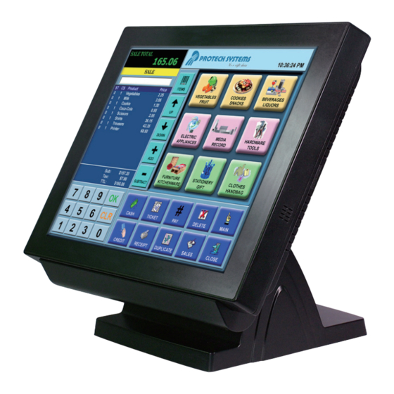
Page 9: Pos System Illustration
Chapter 1 Introduction 1-2. POS SYSTEM ILLUSTRATION Front View Rear View Side View Quarter View Page: 1-3 ′ PA-6970 SERIES USER S MANUAL... - Page 10 Chapter 1 Introduction Rear I/O View Page: 1-4 ′ PA-6970 SERIES USER S MANUAL...
-
Page 11: System Specifications
367 x 270 x 78mm (PPC) Certificate FCC/CE I/O Ports 4 x USB2.0 ports 1 x USB2.0 on side bezel Serial Port 3 x DB-9 (COM 2/3/4) 1 x RJ45 (COM1) +5/12V Selectable 1 x RJ-45 Page: 1-5 ′ PA-6970 SERIES USER S MANUAL... - Page 12 1 x 2.5” SATA SSD (Optional) Display LCD Interface 15” TFT Max. Resolution 1024 x 768 Brightness 250 cd/m Tilt Angel 0~68˚ Touch Screen 5-wire Analog resistive Environment Temperature Operation: 0~35˚C (32~95˚F) Storage: -20~60˚C (-4~140˚F) Humidity 20~90% Page: 1-6 ′ PA-6970 SERIES USER S MANUAL...
-
Page 13: Safety Precautions
Place your PA-6970 on a sturdy, level surface. Be sure to allow enough space around the system to have easy access needs. Avoid installing your PA-6970 Series POS system in extremely hot or cold places. Avoid exposure to sunlight for a long period of time (for example, in a closed car in summer time. - Page 14 If heavy stains are present, moisten a cloth with diluted neutral washing agent or alcohol and then wipe thoroughly with a dry cloth. If dust is accumulated on the case surface, remove it by using a special vacuum cleaner for computers. Page: 1-8 ′ PA-6970 SERIES USER S MANUAL...
-
Page 15: Chapter 2 System Configuration
CHAPTER SYSTEM CONFIGURATION Helpful information that describes the jumper and connector settings, and component locations. Sections included: Jumper & Connector Quick Reference Table Component Locations Configuration and Jumper settings Connector Pin Assignments Page 2-1... -
Page 16: Jumper & Connector Quick Reference Table
JP6, JP27 2-26 Clear CMOS Data Selection 2-27 Printer Connector LPT1 2-28 LVDS Output Resolution Selection JP22, JP23, JP24, JP25 2-29 Security Override Mode Setting JP26 2-29 LVDS Backlight Type Selection JP21 2-30 Page: 2-2 ’ PA-6970 SERIES USER S MANUAL... -
Page 17: Component Locations
CPU Socket DIMM1 DIMM2 JINVDRV1 JINV2 USB5 1 1 1 1 JINV1 JLED2 LVDS1 FAN2 JP21 JP21 COM4-2 JI_BUTTON1 JLED1-1 SW2-1 SPK1 TOUCH2 PS2_1 TOUCH1 PA-6970 Front Connector, Jumper and Component Locations Page: 2-3 ’ PA-6970 SERIES USER S MANUAL... - Page 18 Chapter 2 System Configuration M_PCIE1 PA-6970 Rear Connector, Jumper and Component Locations Page: 2-4 ’ PA-6970 SERIES USER S MANUAL...
-
Page 19: How To Set The Jumpers
PIN1 & PIN2 to create one setting and shorting. You can either connect PIN2 & PIN3 to create another setting. The same jumper diagrams are applied all through this manual. The figure below shows what the manual diagrams look and what they represent. Page: 2-5 ’ PA-6970 SERIES USER S MANUAL... - Page 20 Chapter 2 System Configuration JUMPER DIAGRAMS JUMPER SETTINGS Page: 2-6 ’ PA-6970 SERIES USER S MANUAL...
-
Page 21: Com Port & Vga Connector
CTS1 DTR1 RI / +5V / +12V selectable COM3-1: COM3-1 Connectors The pin assignments are as follows: ASSIGNMENT ASSIGNMENT DCD3 DSR3 RXD3 RTS3 TXD3 CTS3 DTR3 RI / +5V / +12V selectable Page: 2-7 ’ PA-6970 SERIES USER S MANUAL... - Page 22 RI / +5V / +12V selectable Note: All COM ports are selectable for RI, +5V or +12V. For more information, please refer to “2-5. COM RI & Voltage Selection” of this manual. Page: 2-8 ’ PA-6970 SERIES USER S MANUAL...
- Page 23 RI / +5V / +12V selectable Note: All COM ports are selectable for RI, +5V or +12V. For more information, please refer to “2-5. COM RI & Voltage Selection” of this manual. Page: 2-9 ’ PA-6970 SERIES USER S MANUAL...
-
Page 24: Com Port Ri And Voltage Selection
The jumper settings are as follows: SELECTION JUMPER JUMPER ILLUSTRATION SETTING VCC12 Note: Manufacturing Default is RI. 2-6. I-BUTTON CONNECTOR JI-BUTTON1: i-Button Connector The pin assignments are as follows: ASSIGNMENT COM3_DTR_R_I COM3_RXD_R_I Page: 2-10 ’ PA-6970 SERIES USER S MANUAL... -
Page 25: I-Button Function Selection
The jumper settings are as follows: SELECTION JUMPER SETTING JUMPER ILLUSTRATION COM 3 JP14/15/16 i-Button* JP14/15/16 Note: Manufacturing Default is COM3. *When these jumpers are set as ‘i-Button,’ the COM3-1 connector will not function. Page: 2-11 ’ PA-6970 SERIES USER S MANUAL... -
Page 26: Lan & Usb Connector
JPS2USB01: MINI-DIN and USB Connectors The MINI-DIN connector can support keyboard, Y-cable, or PS/2 Mouse. The pin assignments are as follows: ASSIGNMENT ASSIGNMENT VCC5 USB0+ USB0- KDAT VCC5 MDAT V5SB USB1+ KCLK USB1- MCLK JPS2USB01 Page: 2-12 ’ PA-6970 SERIES USER S MANUAL... -
Page 27: Usb Connector
The pin assignments are as follows: ASSIGNMENT USB5- USB5+ USB8: Internal USB Connector The pin assignments are as follows: ASSIGNMENT USB8- USB8+ USB8 USB9: Internal USB Connector The pin assignments are as follows: ASSIGNMENT USB9- USB9+ Page: 2-13 ’ PA-6970 SERIES USER S MANUAL... - Page 28 Chapter 2 System Configuration USB10-1, USB10-2 (Optional): Two USB Connectors The pin assignments are as follows: ASSIGNMENT USB10- USB10+ U SB10-1 U SB10-2 Page: 2-14 ’ PA-6970 SERIES USER S MANUAL...
-
Page 29: Cash Drawer Connector
Write "0"h to I/O space register "50C"h Bit 7 To Close Drawer1 Write "1"h to I/O space register "50C"h Bit 7 Detect Drawer1 Status Read I/O space register "50C"h (GPIO 6) Definition (bit4) Page: 2-15 ’ PA-6970 SERIES USER S MANUAL... -
Page 30: Cash Drawer Power Selection
Chapter 2 System Configuration 2-12. CASH DRAWER POWER SELECTION JP13: Cash Drawer Power Selection The jumper settings are as follows: SELECTION JUMPER SETTING JUMPER ILLUSTRATION +24V +12V Note: Manufacturing Default is +24V. Page: 2-16 ’ PA-6970 SERIES USER S MANUAL... -
Page 31: Led Connector
JLED1-2: Power, HDD, LAN indication LED Connector The pin assignments are as follows: ASSIGNMENT PWR_LED 3.3V HDD_LED LAN1_LINK_ACTJ LAN1_LED0 JLED2: Power indication LED Connector The pin assignments are as follows: ASSIGNMENT HD_LED PWR_LED 3.3V Page: 2-17 ’ PA-6970 SERIES USER S MANUAL... -
Page 32: Fan Connector
Chapter 2 System Configuration 2-14. FAN CONNECTOR FAN1: System Fan Connector The pin assignments are as follows: ASSIGNMENT VCC12 SYS_FANIN SYS_FANOUT FAN2: CPU Fan Connector The pin assignments are as follows: ASSIGNMENT VCC12 SYS_FANIN SYS_FANOUT Page: 2-18 ’ PA-6970 SERIES USER S MANUAL... -
Page 33: Power Connector
J1: Provide 12 Voltage Connector The pin assignments are as follows: ASSIGNMENT VCC12 VCC12 2-16. POWER SWITCH CONNECTOR SW1, SW2-1, SW2-2: Power Switch Connectors The pin assignments are as follows: ASSIGNMENT LPC_PWRBTNJ SW1/ PCH_PWRBTNJ_LOW SW2-2 SW2-1 Page: 2-19 ’ PA-6970 SERIES USER S MANUAL... -
Page 34: Power For Thermal Printer Connector
PRT_PWR1: Power for Thermal Printer Connector The pin assignments are as follows: ASSIGNMENT VCC24SB VCC24SB 2-18. EXTERNAL SPEAKER CONNECTOR SPK1, SPK2: External Speaker Connectors The pin assignments are as follows: ASSIGNMENT SPK_GND SPK1/ SPK_OUT SPK2 Page: 2-20 ’ PA-6970 SERIES USER S MANUAL... -
Page 35: Inverter Connector
ASSIGNMENT +12V LVDS_BKLTEN BRCTR JINV2: Inverter Connector The pin assignments are as follows: ASSIGNMENT +12V +12V LVDS_BKLTEN_R BRCTR JINV3: Inverter Connector The pin assignments are as follows: ASSIGNMENT +12V BRCTR LVDS_BKLTEN +12V Page: 2-21 ’ PA-6970 SERIES USER S MANUAL... -
Page 36: Lvds Voltage Selection
Chapter 2 System Configuration 2-20. LVDS VOLTAGE SELECTION JP7: LVDS Voltage Selection The jumper settings are as follows: SELECTION JUMPER SETTING JUMPER ILLUSTRATION 3.3V Note: Manufacturing Default is 3.3V. Page: 2-22 ’ PA-6970 SERIES USER S MANUAL... -
Page 37: Lvds Connector
RINO1- RINO0+ RINO0- LVDS_VCC LVDS_VCC 2-22. MSR/CARD READER CONNECTOR PS2_1 & PS2_2: MSR/Card Reader Connector The pin assignments are as follows: ASSIGNMENT KB_CLK (Output) PS2_1/ KB_CLK_C (Input) PS2_2 KB_DATA_C (Input) KB_DATA (Output) Page: 2-23 ’ PA-6970 SERIES USER S MANUAL... -
Page 38: Sata & Sata Power Connector
SATA1, SATA2: Serial ATA Connectors The pin assignments are as follows: ASSIGNMENT S AT A1 SATA2 JPWR_4P1, JPWR_4P2: Serial ATA Power Connectors The pin assignments are as follows: ASSIGNMENT JPWR_4P1 VCC12 JPWR_4P2 Page: 2-24 ’ PA-6970 SERIES USER S MANUAL... -
Page 39: Touch Panel Connector
LL (Low Left) Probe UR (Up Right) UL (Up Left) TOUCH2: Touch Panel Connector The pin assignments are as follows: ASSIGNMENT LR (Low Right) LL (Low Left) Probe UR (Up Right) UL (Up Left) Page: 2-25 ’ PA-6970 SERIES USER S MANUAL... -
Page 40: Touch Panel Selection
JUMPER SETTING JUMPER ILLUSTRATION e-Turbo Note: Manufacturing Default is Elo. JP27: Touch Panel Selection The jumper settings are as follows: SELECTION JUMPER SETTING JUMPER ILLUSTRATION JP27 JP27 Note: Manufacturing Default is Elo. Page: 2-26 ’ PA-6970 SERIES USER S MANUAL... -
Page 41: Clear Cmos Data Selection
*To clear CMOS data, you must power-off the computer and set the jumper to “Clear CMOS” as illustrated above. After five to six seconds, set the jumper back to “Normal” and power-on the computer. Page: 2-27 ’ PA-6970 SERIES USER S MANUAL... -
Page 42: Printer Connector
Chapter 2 System Configuration 2-27. PRINTER CONNECTOR LPT1: LPT Connector The pin assignments are as follows: ASSIGNMENT ASSIGNMENT STBJ ALFJ PDR0 ERRJ PDR1 PAR_INITJ PDR2 SLCTINJ PDR3 PDR4 PDR5 PDR6 PDR7 ACKJ BUSY SLCTJ Page: 2-28 ’ PA-6970 SERIES USER S MANUAL... -
Page 43: Lvds Output Resolution Selection
2-29. SECURITY OVERRIDE MODE SETTING JP26: Flash Descriptor Security Override/Intel ME Debug Mode The jumper settings are as follows: SELECTION JUMPER SETTING JUMPER ILLUSTRATION Disable Open JP26 Enable JP26 Note: Manufacturing Default is Disable. Page: 2-29 ’ PA-6970 SERIES USER S MANUAL... -
Page 44: Lvds Backlight Type Selection
Chapter 2 System Configuration 2-30. LVDS BACKLIGHT TYPE SELECTION JP21: LVDS Backlight Type Selection The jumper settings are as follows: SELECTION JUMPER SETTING JUMPER ILLUSTRATION JP21 CCFL JP21 Note: Manufacturing Default is LED. Page: 2-30 ’ PA-6970 SERIES USER S MANUAL... -
Page 45: Chapter 3 Software Utilities
CHAPTER SOFTWARE UTILITIES This chapter provides the detailed information users need to install driver utilities for the system. Sections included: ® Intel Chipset Software Installation Utility VGA Driver Utility LAN Driver Utility Sound Driver Utility Touch Screen Driver Utility Wireless Driver Utility (Optional) Page: 3-1... -
Page 46: Introduction
Chapter 3 Software Utilities 3-1. INTRODUCTION Enclosed with the PA-6970 Series package is our driver utilities, which comes in a CD ROM format. Refer to the following table for driver locations. FILENAME PURPOSE (Assume that CD ROM drive is D:) ®... -
Page 47: Intel Chipset Software Installation Utility
3. Click Setup.exe file for driver installation. 4. Follow the on-screen instructions to complete the installation. 5. Once installation is completed, shut down the system and restart the PA-6970 for the changes to take effect. Page:3-3 ′ PA-6970 SERIES USER S MANUAL... -
Page 48: Vga Driver Utility
Chapter 3 Software Utilities 3-3. VGA DRIVER UTILITY The VGA interface embedded with the PA-6970 series can support a wide range of display types. You can have dual displays via CRT and LVDS interfaces work simultaneously. 1. Win XP Series 2. -
Page 49: Lan Driver Utility
Chapter 3 Software Utilities 3-4. LAN DRIVER UTILITY The PA-6970 Series is enhanced with LAN function that can support various network adapters. Installation platform for the LAN driver is listed as follows: 1. Win XP Series 2. Win 7 Series 3. -
Page 50: Sound Driver Utility
3. Click Setup.exe file for driver installation. 4. Follow the on-screen instructions to complete the installation. 5. Once installation is completed, shut down the system and restart the PA-6970 for the changes to take effect. Page:3-6 ′ PA-6970 SERIES USER S MANUAL... -
Page 51: Touch Screen Driver Utility
3. Click Setup.exe file for driver installation. 4. Follow the on-screen instructions to complete the installation. 5. Once installation is completed, shut down the system and restart the PA-6970 for the changes to take effect. Page:3-7 ′ PA-6970 SERIES USER S MANUAL... -
Page 52: Wireless Driver Utility (Optional)
3. Click Setup.exe file for driver installation. 4. Follow the on-screen instructions to complete the installation. 5. Once installation is completed, shut down the system and restart the PA-6970 for the changes to take effect. Page:3-8 ′ PA-6970 SERIES USER S MANUAL... - Page 53 CHAPTER BIOS SETUP This chapter shows how to set up the AMI BIOS. Sections included: Introduction Entering Setup Main Advanced Chipset Boot Security Save & Exit Page: 4-1...
-
Page 54: Chapter 4 Ami Bios Setup
These provide standard environment for booting an operating system and running pre-boot applications. Following illustration shows Extensible Firmware Interface’s position in the software stack. Page: 4-2 ′ PA-6970 SERIES USER S MANUAL... - Page 55 The BIOS Setup program is accessed by pressing the <Del> or <ESC> key after the POST memory test begins and before the operating system boot begins. The settings are shown below. Page: 4-3 ′ PA-6970 SERIES USER S MANUAL...
-
Page 56: Entering Setup
POST Screen As long as this message is present on the screen you may press the <Del> or <ESC> key to access the Setup program. Page: 4-4 ′ PA-6970 SERIES USER S MANUAL... - Page 57 You may move the cursor by up/down keys to highlight the individual menu items. As you highlight each item, a brief description of the highlighted selection will appear at the bottom of the screen. Page: 4-5 ′ PA-6970 SERIES USER S MANUAL...
-
Page 58: Main
No changeable options Displays the date of current BIOS Time version. ME FW No changeable options Displays the current ME version. Version ME Firmware No changeable options Displays the current ME SKU. Page: 4-6 ′ PA-6970 SERIES USER S MANUAL... - Page 59 BIOS Setup language. Language System Date Month, day, year Specifies the current date. System Time Hour, minute, second Specifies the current time. Access Level No changeable options Displays the current user level. Page: 4-7 ′ PA-6970 SERIES USER S MANUAL...
-
Page 60: Advanced
SATA device options settings. USB Configuration Sub-Menu USB configuration parameters. W83627UHG Super Sub-Menu System super IO chip configuration. IO Configuration W83627UHG H/W Sub-Menu Monitor hardware status. Monitor WatchDog Sub-Menu Watchdog timer for system reset. Configuration Page: 4-8 ′ PA-6970 SERIES USER S MANUAL... - Page 61 Wake up Multiple options Sets the minute for wake up. minute ranging from 0 to 59 Wake up Multiple options Sets the second for wake up. second ranging from 0 to 59 Page: 4-9 ′ PA-6970 SERIES USER S MANUAL...
- Page 62 Wake system - Disabled Enable wake up feature with dynamic with dynamic time. - Enabled time Wake up Multiple options Sets the minute for wake up. minute increase ranging from 1 to 5 Page: 4-10 ′ PA-6970 SERIES USER S MANUAL...
- Page 63 Reports the current CPU Speed Processor No changeable options Displays number of physical cores in Cores processor. Intel HT No changeable options Reports if Intel Hyper-Threading Technology Technology is supported by processor Page: 4-11 ′ PA-6970 SERIES USER S MANUAL...
- Page 64 Displays size of L2 Cache. L3 Cache No changeable options Displays size of L3 Cache. Active - All Choose the number of cores to be Processor enabled in current processor. - 1/2/3… Cores Page: 4-12 ′ PA-6970 SERIES USER S MANUAL...
- Page 65 Displays the drive installed on this SATA port 0. Shows [Empty] if no drive is installed. SATA1 [drive] Displays the drive installed on this SATA port 1. Shows [Empty] if no drive is installed. Page: 4-13 ′ PA-6970 SERIES USER S MANUAL...
- Page 66 Displays number of available USB devices. Legacy USB - Disabled Enables support for legacy USB. Support - Enabled - Auto EHCI Hand-off - Disabled This is a workaround for OSes w/o EHCI hand-off support. - Enabled Page: 4-14 ′ PA-6970 SERIES USER S MANUAL...
- Page 67 Sub-menu Set Parameters of Serial Port 2 Configuration (COM3) (COM3) Serial Port 3 Sub-menu Set Parameters of Serial Port 3 Configuration (COM4) (COM4) Parallel Port Sub-menu Set Parameters for LPT port. Configuration Page: 4-15 ′ PA-6970 SERIES USER S MANUAL...
- Page 68 Displays current settings of COM 1. Change - Auto Select IRQ and I/O Settings resource for the COM 1. - IO=3F8h; IRQ=4 - IO=3F8h; IRQ=3,4,5,6,7,10,11,12 - IO=2F8h; IRQ=3,4,5,6,7,10,11,12 - IO=3E8h; IRQ=3,4,5,6,7,10,11,12 - IO=2E8h; IRQ=3,4,5,6,7,10,11,12 Page: 4-16 ′ PA-6970 SERIES USER S MANUAL...
- Page 69 Displays current settings of COM 2. Change - Auto Select IRQ and I/O Settings resource for the COM 2. - IO=2F8h; IRQ=3 - IO=3F8h; IRQ=3,4,5,6,7,10,11,12 - IO=2F8h; IRQ=3,4,5,6,7,10,11,12 - IO=3E8h; IRQ=3,4,5,6,7,10,11,12 - IO=2E8h; IRQ=3,4,5,6,7,10,11,12 Page: 4-17 ′ PA-6970 SERIES USER S MANUAL...
- Page 70 Displays current settings of COM 3. Change - Auto Select IRQ and I/O Settings resource for the COM 3. - IO=3E8h; IRQ=3 - IO=3F8h; IRQ=3,4,5,6,7,10,11,12 - IO=2F8h; IRQ=3,4,5,6,7,10,11,12 - IO=3E8h; IRQ=3,4,5,6,7,10,11,12 - IO=2E8h; IRQ=3,4,5,6,7,10,11,12 Page: 4-18 ′ PA-6970 SERIES USER S MANUAL...
- Page 71 Displays current settings of COM 4. Change - Auto Select IRQ and I/O Settings resource for the COM 4. - IO=2E8h; IRQ=3 - IO=3F8h; IRQ=3,4,5,6,7,10,11,12 - IO=2F8h; IRQ=3,4,5,6,7,10,11,12 - IO=3E8h; IRQ=3,4,5,6,7,10,11,12 - IO=2E8h; IRQ=3,4,5,6,7,10,11,12 Page: 4-19 ′ PA-6970 SERIES USER S MANUAL...
- Page 72 Displays current settings of the printer port. Change - Auto Select IRQ and I/O resource Settings for the printer port.. - IO=378h; IRQ=5 - IO=378h; IRQ=5,6,7,10,11,12 - IO=278h; IRQ=5,6,7,10,11,12 - IO=3BCh; IRQ=5,6,7,10,11,12 Page: 4-20 ′ PA-6970 SERIES USER S MANUAL...
- Page 73 - ECP and EPP 1.7 Mode printers. EPP is Enhanced Parallel Port mode, a high-speed bi-directional mode for non-printer peripherals. ECP is Enhanced Capability Port mode, a high-speed bi-directional mode for printers and scanners. Page: 4-21 ′ PA-6970 SERIES USER S MANUAL...
- Page 74 Displays voltage level of the +VCORE in supply. +12V No changeable options Displays voltage level of the +12V in supply. +1.5V No changeable options Displays voltage level of the +1.5V in supply. Page: 4-22 ′ PA-6970 SERIES USER S MANUAL...
- Page 75 Displays voltage level of the +5V in supply. VSB5 No changeable options Displays voltage level of the +5VSB in supply. VBAT No changeable options Displays voltage level of the backup CMOS battery. Page: 4-23 ′ PA-6970 SERIES USER S MANUAL...
- Page 76 CPU fan mode - Manual Mode Configures the smart fan. - Thermal CruiseTM Mode CPU fan PWM Multiple options CPU Fan PWM output duty output duty ranging from 0 to 255 Page: 4-24 ′ PA-6970 SERIES USER S MANUAL...
- Page 77 Watchdog - Second Selects unit for watchdog timer. count mode - Minute Watchdog Multiple options Sets the desired value for watchdog timeout value ranging from 0 to 255 timer. 0 means disabled. Page: 4-25 ′ PA-6970 SERIES USER S MANUAL...
-
Page 78: Chipset
Chapter 4 AMI BIOS Setup 4-5. CHIPSET Chipset screen BIOS Setting Options Description/Purpose PCH-IO Configuration Sub-menu PCH Parameters. System Agent (SA) Sub-menu System Agent (SA) Parameters. Configuration Page: 4-26 ′ PA-6970 SERIES USER S MANUAL... - Page 79 - Power On Power Off keeps the power off till the power button is pressed. Power On makes system power on after restores AC power to the board. Page: 4-27 ′ PA-6970 SERIES USER S MANUAL...
- Page 80 Displays the IVB source code module RC Version version VT-d No changeable options Display this chipset support VT-d or Capability not. Graphics Sub-menu Configure Graphic Settings. Configuration Memory Sub-menu Memory Configuration Parameters Configuration Page: 4-28 ′ PA-6970 SERIES USER S MANUAL...
- Page 81 IGFX VBIOS No changeable options Displays the VBIOS version of Version integrated graphic controller. IGfx Frequency No changeable options Displays the frequency of integrated graphic controller. LCD Control Sub-menu LCD Control Parameters. Page: 4-29 ′ PA-6970 SERIES USER S MANUAL...
- Page 82 Chapter 4 AMI BIOS Setup LCD Control screen BIOS Setting Options Description/Purpose Primary IGFX - LVDS + CRT Select primary display device Boot Display - CRT - LVDS Page: 4-30 ′ PA-6970 SERIES USER S MANUAL...
- Page 83 Chapter 4 AMI BIOS Setup Memory Configuration screen BIOS Setting Options Description/Purpose Memory No changeable option Displays the detail DRAM Information lists. information on platform. Page: 4-31 ′ PA-6970 SERIES USER S MANUAL...
-
Page 84: Boot
Allows setting boot option listed in #1~#n Hard Drive BBS Priorities. - Disabled Hard Drive Sub-Menu Allow user to select boot order of BBS Priorities available drive(s) Sub-Menu Configure Option ROM execution, parameters boot options filters, etc. Page: 4-32 ′ PA-6970 SERIES USER S MANUAL... -
Page 85: Security
4-7. SECURITY Security screen BIOS Setting Options Description/Purpose Administrator Password can be 3-20 Specifies the administrator password. Password alphanumeric characters. User Password Password can be 3-20 Specifies the user password. alphanumeric characters. Page: 4-33 ′ PA-6970 SERIES USER S MANUAL... -
Page 86: Save & Exit
Discard No changeable options Resets without saving any changes Changes and made in BIOS settings. Reset Save Changes No changeable options Saves the changes done in BIOS settings so far. Page: 4-34 ′ PA-6970 SERIES USER S MANUAL... - Page 87 No changeable options Saves the current values as user Defaults defaults. Restore User No changeable options Loads the user defaults for BIOS Defaults settings. Boot Override - [drive(s)] Forces to boot from selected [drive(s)]. Page: 4-35 ′ PA-6970 SERIES USER S MANUAL...
-
Page 88: Appendix A System Assembly
APPENDIX SYSTEM ASSEMBLY This appendix contains exploded diagrams and part numbers of the PA- 6970 system. Sections included: Exploded Diagram for PA-6970 Open & Close Exploded Diagram for PA-6970 Stand Exploded Diagram for PA-6970 LCD Holder Exploded Diagram for PA-6970 LCD Disassembly Exploded Diagram for PA-6970 LCD Panel Exploded Diagram for PA-6970 Inside Cover Exploded Diagram for PA-6970 Main Board... - Page 89 Appendix A System Assembly Exploded Diagram for PA-6970 2 Display Exploded Diagram for PA-6970 VFD Module Page: A-2 ′ PA-6970 SERIES USER S MANUAL...
-
Page 90: Exploded Diagram For Pa-6970 Open & Close
Appendix A System Assembly EXPLODED DIAGRAM FOR PA-6970 OPEN & CLOSE Page: A-3 ′ PA-6970 SERIES USER S MANUAL... -
Page 91: Exploded Diagram For Pa-6970 Stand
Appendix A System Assembly EXPLODED DIAGRAM FOR PA-6970 STAND Page: A-4 ′ PA-6970 SERIES USER S MANUAL... -
Page 92: Exploded Diagram For Pa-6970 Lcd Holder
Appendix A System Assembly EXPLODED DIAGRAM FOR PA-6970 LCD HOLDER Page: A-5 ′ PA-6970 SERIES USER S MANUAL... - Page 93 Appendix A System Assembly Page: A-6 ′ PA-6970 SERIES USER S MANUAL...
-
Page 94: Exploded Diagram For Pa-6970 Lcd Disassembly
Appendix A System Assembly EXPLODED DIAGRAM FOR PA-6970 LCD DISASSEMBLY Page: A-7 ′ PA-6970 SERIES USER S MANUAL... - Page 95 Appendix A System Assembly Page: A-8 ′ PA-6970 SERIES USER S MANUAL...
-
Page 96: Exploded Diagram For Pa-6970 Lcd Panel
Appendix A System Assembly EXPLODED DIAGRAM FOR PA-6970 LCD PANEL Page: A-9 ′ PA-6970 SERIES USER S MANUAL... - Page 97 Appendix A System Assembly Page: A-10 ′ PA-6970 SERIES USER S MANUAL...
-
Page 98: Exploded Diagram For Pa-6970 Inside Cover
Appendix A System Assembly EXPLODED DIAGRAM FOR PA-6970 INSIDE COVER Page: A-11 ′ PA-6970 SERIES USER S MANUAL... -
Page 99: Exploded Diagram For Pa-6970 Main Board
Appendix A System Assembly EXPLODED DIAGRAM FOR PA-6970 MAIN BOARD Page: A-12 ′ PA-6970 SERIES USER S MANUAL... - Page 100 Appendix A System Assembly Page: A-13 ′ PA-6970 SERIES USER S MANUAL...
-
Page 101: Exploded Diagram For Pa-6970 Inverter Board
Appendix A System Assembly EXPLODED DIAGRAM FOR PA-6970 INVERTER BOARD Page: A-14 ′ PA-6970 SERIES USER S MANUAL... -
Page 102: Exploded Diagram For Pa-6970 Hdd Module
Appendix A System Assembly EXPLODED DIAGRAM FOR PA-6970 HDD MODULE Page: A-15 ′ PA-6970 SERIES USER S MANUAL... -
Page 103: Exploded Diagram For Pa-6970 Rfid Module
Appendix A System Assembly EXPLODED DIAGRAM FOR PA-6970 RFID MODULE Page: A-16 ′ PA-6970 SERIES USER S MANUAL... -
Page 104: Exploded Diagram For Pa-6970 Msr Module
Appendix A System Assembly EXPLODED DIAGRAM FOR PA-6970 MSR MODULE Page: A-17 ′ PA-6970 SERIES USER S MANUAL... -
Page 105: Exploded Diagram For Pa-6970 2
Appendix A System Assembly EXPLODED DIAGRAM FOR PA-6970 2 DISPLAY Page: A-18 ′ PA-6970 SERIES USER S MANUAL... -
Page 106: Exploded Diagram For Pa-6970 Vfd Module
Appendix A System Assembly EXPLODED DIAGRAM FOR PA-6970 VFD MODULE Page: A-19 ′ PA-6970 SERIES USER S MANUAL... - Page 107 APPENDIX TECHNICAL SUMMARY This appendix will give you a brief introduction of the allocation maps for the system resources. Sections included: Block Diagram Interrupt Map DMA Channels Map I / O Map Watchdog Timer Configuration Flash BIOS Update Page: B-1...
-
Page 108: Appendix B Technical Summary
SATA Connector *2 SATA SPI Flash ROM ALC 888 High Definition Codec Cash Drawer Touch Controller GPIO RJ11 x1 LOW PIN COUNT MOUSE COM2 Parallel WINBOND Keyboard Serial 1/2/3/4 W83627UHG Card Reader & i-Button Page: B-2 ′ PA-6970 SERIES USER S MANUAL... -
Page 109: Interrupt Map
High Definition Audio Controller ® Intel 6 Series/C200 Series Chipset Family USB Enhanced Host Controller - 1C26 Microsoft ACPI-Compliant System Microsoft ACPI-Compliant System Microsoft ACPI-Compliant System Microsoft ACPI-Compliant System Microsoft ACPI-Compliant System Page: B-3 ′ PA-6970 SERIES USER S MANUAL... - Page 110 Microsoft ACPI-Compliant System Microsoft ACPI-Compliant System Microsoft ACPI-Compliant System Microsoft ACPI-Compliant System Microsoft ACPI-Compliant System Microsoft ACPI-Compliant System Microsoft ACPI-Compliant System Microsoft ACPI-Compliant System Microsoft ACPI-Compliant System Microsoft ACPI-Compliant System Microsoft ACPI-Compliant System Page: B-4 ′ PA-6970 SERIES USER S MANUAL...
- Page 111 Microsoft ACPI-Compliant System Microsoft ACPI-Compliant System Microsoft ACPI-Compliant System Microsoft ACPI-Compliant System Microsoft ACPI-Compliant System Microsoft ACPI-Compliant System Microsoft ACPI-Compliant System Microsoft ACPI-Compliant System Microsoft ACPI-Compliant System Microsoft ACPI-Compliant System Microsoft ACPI-Compliant System Page: B-5 ′ PA-6970 SERIES USER S MANUAL...
- Page 112 Microsoft ACPI-Compliant System Microsoft ACPI-Compliant System Microsoft ACPI-Compliant System Microsoft ACPI-Compliant System Microsoft ACPI-Compliant System Microsoft ACPI-Compliant System Microsoft ACPI-Compliant System Microsoft ACPI-Compliant System Microsoft ACPI-Compliant System Microsoft ACPI-Compliant System Microsoft ACPI-Compliant System Page: B-6 ′ PA-6970 SERIES USER S MANUAL...
- Page 113 Microsoft ACPI-Compliant System Microsoft ACPI-Compliant System Microsoft ACPI-Compliant System Microsoft ACPI-Compliant System Microsoft ACPI-Compliant System Microsoft ACPI-Compliant System Microsoft ACPI-Compliant System Microsoft ACPI-Compliant System Microsoft ACPI-Compliant System Microsoft ACPI-Compliant System Microsoft ACPI-Compliant System Page: B-7 ′ PA-6970 SERIES USER S MANUAL...
- Page 114 3 - 1C14 ® 4294967293 Intel 6 Series/C200 Series Chipset Family PCI Express Root Port 2 - 1C12 ® 4294967294 Intel 6 Series/C200 Series Chipset Family PCI Express Root Port 1 - 1C10 Page: B-8 ′ PA-6970 SERIES USER S MANUAL...
-
Page 115: Dma Channels Map
Appendix B Technical Summary DMA CHANNELS MAP DMA CHANNEL ASSIGNMENT Direct memory access controller Page: B-9 ′ PA-6970 SERIES USER S MANUAL... -
Page 116: I/O Map
Direct memory access controller 0x00000090-0x0000009F Motherboard resources 0x000000A0-0x000000A1 Programmable interrupt controller 0x000000A2-0x000000BF Motherboard resources 0x000000C0-0x000000DF Direct memory access controller 0x000000E0-0x000000EF Motherboard resources 0x000000F0-0x000000FF Numeric data processor 0x00000170-0x00000177 ATA Channel 1 0x000001F0-0x000001F7 ATA Channel 0 Page: B-10 ′ PA-6970 SERIES USER S MANUAL... - Page 117 6 Series/C200 Series Chipset Family PCI Express Root Port 2 - 1C12 0x0000E000-0x0000EFFF Realtek PCIe GBE Family Controller ® 0x0000F000-0x0000F03F Intel HD Graphics Family ® 0x0000F040-0x0000F05F Intel 6 Series/C200 Series Chipset Family SMBus Controller - 1C22 Page: B-11 ′ PA-6970 SERIES USER S MANUAL...
- Page 118 6 Series/C200 Series Chipset Family 4 port Serial ATA Storage Controller - 1C00 Note: The resource information is gathered in Windows 7 (the IRQ may be assigned differently depending on your OS). Page: B-12 ′ PA-6970 SERIES USER S MANUAL...
-
Page 119: Watchdog Timer Configuration
To exit the Extended Function Mode, writing 0xAA to the EFER is required. Once the chip exits the Extended Function Mode, it is in the normal running mode and is ready to enter the configuration mode. Page: B-13 ′ PA-6970 SERIES USER S MANUAL... - Page 120 ;------ Select Logical Device 8 of watchdog timer -------------------------------------------- ;------ Set second as counting unit -------------------------------------------------------------- 0f5h not 08h ;------ Set timeout interval as 30seconds and start counting --------------------------------- 0f6h ;------ Exit the extended function mode -------------------------------------------------------- 0aah Page: B-14 ′ PA-6970 SERIES USER S MANUAL...
-
Page 121: Flash Bios Update
System will go into the BIOS setup menu. Select [Boot] menu. Select [Hard Drive BBS Priorities], set the USB bootable device to be the boot device. Press <F4> key to save configuration and exit the BIOS setup menu. Page: B-15 ′ PA-6970 SERIES USER S MANUAL... - Page 122 Appendix B Technical Summary Page: B-16 ′ PA-6970 SERIES USER S MANUAL...
- Page 123 ?” to see all the definition of each control options. The recommended options for BIOS ROM update include following parameters: Program main BIOS image /B: Program Boot Block /N: Program NVRAM /X: Do not check ROM ID Page: B-17 ′ PA-6970 SERIES USER S MANUAL...
- Page 124 User can restart the system and boot up with new BIOS now. Update is complete after restart. Verify during following boot that the BIOS version displayed at initialization screen has changed. Page: B-18 ′ PA-6970 SERIES USER S MANUAL...
- Page 125 Appendix B Technical Summary Page: B-19 ′ PA-6970 SERIES USER S MANUAL...
Need help?
Do you have a question about the PA-6970 Series and is the answer not in the manual?
Questions and answers