
Subscribe to Our Youtube Channel
Related Manuals for protech POS-6511 Series


Summary of Contents for protech POS-6511 Series
- Page 1 USER’S MANUAL POS-6511 Series POS System Powered by ® Intel Sandy Bridge Platform POS-6511 Series M1...
- Page 2 Preface POS-6511 Series POS System With LCD / Touchscreen PREFACE COPYRIGHT NOTICE This user’s manual is meant to assist users in installing and setting up the system. The information contained in this document is subject to change without any notice.
- Page 3 Preface FCC NOTICE This equipment has been tested and found to comply with the limits for a Class A digital device, pursuant to part 15 of the FCC Rules. These limits are designed to provide reasonable protection against harmful interference when the equipment is operated in a commercial environment.
- Page 4 Contents TABLE OF CONTENTS CHAPTER 1 INTRODUCTION About This Manual ............POS System Illustration ..........System Specifications ........... Safety Precautions ............CHAPTER 2 SYSTEM CONFIGURATION Jumper & Connector Quick Reference Table ....Component Locations ........... How to Set the Jumpers ..........COM Port Connector …………………………………...
-
Page 5: Table Of Contents
Contents CHAPTER 3 SOFTWARE UTILITIES Introduction ..............® Intel Chipset Software Installation Utility ....VGA Driver Utility …………………………….…….. LAN Driver Utility ............Sound Driver Utility ............. Touch Screen Driver Utility ……………..…………… Wireless Driver Utility (Optional) …………………… CHAPTER 4 AMI BIOS SETUP Introduction .............. - Page 6 Contents APPENDIX B TECHNICAL SUMMARY Block Diagram ................Interrupt Map ................DMA Channels Map ..............Memory Map ................I/O Map ..................B-10 Watchdog Timer Configuration ..........B-13 Flash BIOS Update ……............B-15 APPENDIX C QUICK MANUAL Assembly Procedure of VFD ............ i-Button Decoder API ...............
- Page 7 CHAPTER INTRODUCTION This chapter gives you the information for the POS-6511. It also outlines the system specifications. Sections included: About This Manual POS System Illustration System Specifications Safety Precautions Experienced users can jump to chapter 2 on page 2-1 for a quick start.
-
Page 8: Appendix B Technical Summary
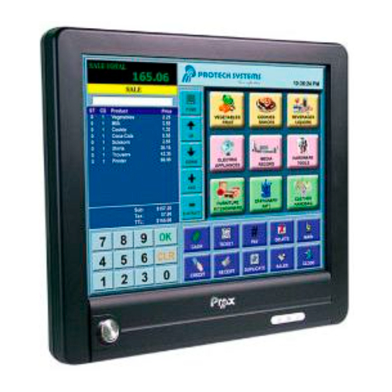
Chapter 1 Introduction 1-1. ABOUT THIS MANUAL Thank you for purchasing our POS-6511 Series System. The POS-6511 is an updated system designed to be comparable with the highest performance of IBM AT personal computers. The POS-6511 provides faster processing speed, greater expandability and can handle more tasks than before. - Page 9 Chapter 1 Introduction 1-2. POS SYSTEM ILLUSTRATION POS-6511 Page: 1-3 POS-6511 SERIES USER S MANUAL...
- Page 10 Chapter 1 Introduction POS-6511-PPC Page: 1-4 POS-6511 SERIES USER S MANUAL...
- Page 11 Chapter 1 Introduction POS-6511-MIT Page: 1-5 POS-6511 SERIES USER S MANUAL...
- Page 12 Universal Serial Bus Port: 4 x USB2.0 ports 1 x USB2.0 on side bezel PARALLEL PORT: 1 x parallel port, bi-directional, supports SPP/EPP/ECP LAN Function: 1 x 10/100/1000 Mbps Page: 1-6 POS-6511 SERIES USER S MANUAL...
- Page 13 Interface) + Fingerprint (USB Interface) MSR / i-Button / RFID (Optional): External vertical module, MSR, Read only, JIS-I or II, ISO Tracker 1+2+3; I-button, Read only; RFID, Read / Write, ISO 14443A 13.56MHz (USB Interface) Page: 1-7 POS-6511 SERIES USER S MANUAL...
- Page 14 Place your POS-6511 on a sturdy, level surface. Be sure to allow enough space around the system to have easy access needs. b. Avoid installing your POS-6511 Series POS system in extremely hot or cold places. c. Avoid exposure to sunlight for a long period of time (for example, in a closed car in summer time.
- Page 15 If heavy stains are present, moisten a cloth with diluted neutral washing agent or alcohol and then wipe thoroughly with a dry cloth. d. If dust is accumulated on the case surface, remove it by using a special vacuum cleaner for computers. Page: 1-9 POS-6511 SERIES USER S MANUAL...
- Page 16 CHAPTER SYSTEM CONFIGURATION Helpful information that describes the jumper and connector settings, and component locations. Sections included: Jumper & Connector Quick Reference Table Component Locations Configuration and Jumper settings Connector Pin Assignments Page 2-1...
- Page 17 LVDS1 2-22 SATA & SATA Power Connector SATA1, JPWR_4P1 2-23 Touch Panel Connector JTP1 2-23 Touch Panel Selection JP20 2-24 Clear CMOS Data Selection 2-25 Compact Flash Connector 2-26 Printer Connector LPT1 Page: 2-2 ’ POS-6511 SERIES USER S MANUAL...
- Page 18 Chapter 2 System Configuration 2-2. COMPONENT LOCATIONS M/B: PB-6056RA VGA1 JRJ45USB1 JPS2USB1 COM4 PWR_IN1 I_BUTTON1 POS-6511 Mainboard Front Connector, Jumper and Component locations Page: 2-3 ’ POS-6511 SERIES USER S MANUAL...
- Page 19 Chapter 2 System Configuration POS-6511 Mainboard Rear Connector, Jumper and Component locations Page: 2-4 ’ POS-6511 SERIES USER S MANUAL...
- Page 20 PIN1 & PIN2 to create one setting and shorting. You can either connect PIN2 & PIN3 to create another setting. The same jumper diagrams are applied all through this manual. The figure below shows what the manual diagrams look and what they represent. Page: 2-5 ’ POS-6511 SERIES USER S MANUAL...
- Page 21 Chapter 2 System Configuration JUMPER DIAGRAMS JUMPER SETTINGS Page: 2-6 ’ POS-6511 SERIES USER S MANUAL...
- Page 22 RTS1 CTS1 RI / +5V / +12V selectable COM2: COM2 Connector The pin assignments are as follows: ASSIGNMENT DCD2 COM2 RXD2 TXD2 DTR2 DSR2 RTS2 CTS2 RI / +5V / +12V selectable Page: 2-7 ’ POS-6511 SERIES USER S MANUAL...
- Page 23 RTS3 CTS3 RI / +5V / +12V selectable COM4: COM4 Connector The pin assignments are as follows: ASSIGNMENT DCD4 COM4 RXD4 TXD4 DTR4 DSR4 RTS4 CTS4 RI / +5V / +12V selectable Page: 2-8 ’ POS-6511 SERIES USER S MANUAL...
- Page 24 TXD4 DTR4 DSR4 RTS4 CTS4 RI / +5V / +12V selectable All COM ports are selectable for RI, +5V and +12V. Refer to the section 2-5 COM Port RI & Voltage Selection. Page: 2-9 ’ POS-6511 SERIES USER S MANUAL...
- Page 25 2-5. COM PORT RI & VOLTAGE SELECTION JP_COM1 , JP_COM2, JP_COM3, JP_COM4: COM Port RI & Voltage Selection The jumper settings are as follows: JUMPER JUMPER SELECTION SETTINGS ILLUSTRATION (default) VCC12 *** Manufacturing Default – RI Page: 2-10 ’ POS-6511 SERIES USER S MANUAL...
- Page 26 Chapter 2 System Configuration 2-6. VGA CONNECTOR VGA1: VGA Connector The pin assignments are as follows: ASSIGNMENT VGA1 GREEN BLUE DDCA DATA HSYNC VSYNC DDCA CLK Page: 2-11 ’ POS-6511 SERIES USER S MANUAL...
- Page 27 The jumper settings are as follows: JUMPER JUMPER SETTINGS SELECTION ILLUSTRATION i-Button COM 3 (default) *** Manufacturing Default – COM3 When the jumpers are set as ‘i-Button’, the COM3 connector is not functional. Page: 2-12 ’ POS-6511 SERIES USER S MANUAL...
- Page 28 2-9. LAN & USB CONNECTOR JRJ45USB1: LAN & USB Connector The pin assignments are as follows: Green Orange ASSIGNMENT LAN1_MDIP0 LAN1_MDIN0 LAN1_MDIP1 LAN1_MDIN1 LAN1_MDIP2 LAN1_MDIN2 LAN1_MDIP3 JRJ45USB1 LAN1_MDIN3 ASSIGNMENT VCC5 USB0- USB0+ VCC5 USB1- USB1+ Page: 2-13 ’ POS-6511 SERIES USER S MANUAL...
- Page 29 ASSIGNMENT USB4- USB4+ VCC5 USB2: Internal USB Connector The pin assignments are as follows: ASSIGNMENT USB5- USB5+ VCC5 USB3: Internal USB Connector The pin assignments are as follows: ASSIGNMENT USB8- USB8+ VCC5 Page: 2-14 ’ POS-6511 SERIES USER S MANUAL...
- Page 30 JPS2USB1: Mini-DIN and USB Connectors Mini-DIN connector can support keyboard, Y-cable, or PS/2 Mouse. The pin assignments are as follows: ASSIGNMENT USB3+ USB3- VCC5 USB2+ USB2- VCC5 KDAT MDAT V5SB KCLK MCLK Page: 2-15 ’ POS-6511 SERIES USER S MANUAL...
- Page 31 Read I/O space register "50C"h (GPIO 6) Definition (bit6) 2-13. CASH DRAWER POWER SELECTION JP18: Cash Drawer Power Selection The jumper settings are as follows: JUMPER SELECTION JUMPER SETTING ILLUSTRATION +12V +24V (default) *** Manufacturing Default – +24V Page: 2-16 ’ POS-6511 SERIES USER S MANUAL...
- Page 32 2-15. POWER CONNECTOR J1: Provide 12 Voltage Connector The pin assignments are as follows: ASSIGNMENT VCC12 VCC12 2-16. POWER SWITCH CONNECTOR SW1: Power Switch Connector The pin assignments are as follows: ASSIGNMENT PWR_SW Page: 2-17 ’ POS-6511 SERIES USER S MANUAL...
- Page 33 The pin assignments are as follows: ASSIGNMENT CPUFANIN CPUFANOUT SYS_FAN1: System Fan Connector The pin assignments are as follows: ASSIGNMENT CPUFAN SYS_FAN2: System Fan Connector The pin assignments are as follows: ASSIGNMENT CPUFAN Page: 2-18 ’ POS-6511 SERIES USER S MANUAL...
- Page 34 The pin assignments are as follows: ASSIGNMENT +12V BRCTR LVDS_BKLTEN +12V 2-20. BACKLIGHT TYPE SELECTION JP13: Backlight type Selection The jumper settings are as follows: JUMPER SELECTION JUMPER SETTING ILLUSTRATION CCFL (default) *** Manufacturing Default – CCFL Page: 2-19 ’ POS-6511 SERIES USER S MANUAL...
- Page 35 KB_CLK_C (Input) KB_DATA_C (Input) KB_DATA (Output) 2-22. LVDS VOLTAGE SELECTION JP12: LVDS Voltage Selection The pin assignments are as follows: JUMPER SELECTION JUMPER SETTING ILLUSTRATION 3.3V (default) *** Manufacturing Default – 3.3V Page: 2-20 ’ POS-6511 SERIES USER S MANUAL...
- Page 36 Chapter 2 System Configuration 2-23. LVDS CONNECTOR LVDS1: LVDS connector The pin assignments are as follows: ASSIGNMENT ASSIGNMENT LVDS_VCC CLKO+ CLKO- RINO2+ RINO2- RINO1+ RINO1- RINO0+ RINO0- RINO3+ RINO3- LVDS_VCC LVDS_VCC Page: 2-21 ’ POS-6511 SERIES USER S MANUAL...
- Page 37 Chapter 2 System Configuration 2-24. SATA & SATA POWER CONNECTOR SATA1: Serial ATA Connector The pin assignments are as follows: ASSIGNMENT SATA1 JPWR_4P1: Serial ATA Power Connector The pin assignments are as follows: ASSIGNMENT VCC12 Page: 2-22 ’ POS-6511 SERIES USER S MANUAL...
- Page 38 UR (Up Right) UL (Up Left) 2-26. TOUCH PANEL SELECTION JP20: Touch Panel Selection The jumper settings are as follows: JUMPER SELECTION JUMPER SETTING ILLUSTRATION e-Turbo (default) *** Manufacturing Default – Elo Page: 2-23 ’ POS-6511 SERIES USER S MANUAL...
- Page 39 To clear CMOS data, users must power-off the computer and set the jumper to “Clear CMOS” as illustrated above. After five to six seconds, set the jumper back to “Normal” and power-on the computer. Page: 2-24 ’ POS-6511 SERIES USER S MANUAL...
- Page 40 Chapter 2 System Configuration 2-28. COMPACT FLASH CONNECTOR CF1: Compact Flash Connector The pin assignments are as follows: ASSIGNMENT ASSIGNMENT CSJ1 CSJ3 SDIORDJ SDIOWRJ IRQ14 -CSEL RESETJ IORDJ ACKJ CF_LEDJ -PDIAG Page: 2-25 ’ POS-6511 SERIES USER S MANUAL...
- Page 41 Chapter 2 System Configuration 2-29. PRINTER CONNECTOR LPT1: Printer Connector The pin assignments are as follows: ASSIGNMENT ASSIGNMENT STBJ ALFJ PDR0 ERRJ PDR1 PAR_INITJ PDR2 SLCTINJ PDR3 PDR4 PDR5 PDR6 PDR7 ACKJ BUSY SLCTJ Page: 2-26 ’ POS-6511 SERIES USER S MANUAL...
-
Page 42: Chapter 3 Software Utilities
CHAPTER SOFTWARE UTILITIES This chapter provides the detailed information users need to install driver utilities for the system. Sections included: ® Intel Chipset Software Installation Utility VGA Driver Utility LAN Driver Utility Sound Driver Utility Touch Screen Driver Utility Wireless Driver Utility (Optional) Page: 3-1... -
Page 43: Introduction
Chapter 3 Software Utilities 3-1. INTRODUCTION Enclosed with the POS-6511 Series package is our driver utilities, which comes in a CD ROM format. Refer to the following table for driver locations. Filename Purpose (Assume that CD ROM drive is D:) -
Page 44: Intel Chipset Software Installation Utility
(depending on your OS platform). Click Setup.exe file for driver installation. Follow the on-screen instructions to complete the installation. Once installation is completed, shut down the system and restart the POS-6511 for the changes to take effect. ′ Page:3-3 POS-6511 SERIES USER S MANUAL... -
Page 45: Vga Driver Utility
Chapter 3 Software Utilities 3-3. VGA DRIVER UTILITY The VGA interface embedded with the POS-6511 series can support a wide range of display types. You can have dual displays via CRT and LVDS interfaces work simultaneously. 1. Win XP Series 2. -
Page 46: Lan Driver Utility
Chapter 3 Software Utilities 3-4. LAN DRIVER UTILITY The POS-6511 Series is enhanced with LAN function that can support various network adapters. Installation platform for the LAN driver is listed as follows: 1. Win XP Series 2. Win 7 Series For more details on the Installation procedure, please refer to the Readme.txt file found on LAN Driver Utility. -
Page 47: Sound Driver Utility
(depending on your OS platform). Click Setup.exe file for driver installation. Follow the on-screen instructions to complete the installation. Once installation is completed, shut down the system and restart the POS-6511 for the changes to take effect. Page:3-6 ′ POS-6511 SERIES USER S MANUAL... -
Page 48: Touchscreen Driver Utility
Click Setup.exe file for driver installation. Follow the on-screen instructions to complete the installation. Once installation is completed, shut down the system and restart the POS-6511 for the changes to take effect. ′ Page:3-7 POS-6511 SERIES USER S MANUAL... -
Page 49: Wireless Driver Utility (Optional)
Wireless driver is located. Click Setup.exe file for driver installation. Follow the on-screen instructions to complete the installation. Once installation is completed, shut down the system and restart the POS-6511 for the changes to take effect. Page:3-8 ′ POS-6511 SERIES USER S MANUAL... -
Page 50: Introduction
CHAPTER BIOS SETUP This chapter shows how to set up the AMI BIOS. Section includes: Introduction Entering Setup Main Advanced Chipset Boot Security Save & Exit Page: 4-1... - Page 51 Chapter 4 AMI BIOS Setup 4-1. INTRODUCTION The board POS-6511 uses an AMI Aptio BIOS that is stored in the Serial Peripheral Interface Flash Memory (SPI Flash) and can be updated. The SPI Flash contains the BIOS Setup program, Power-on Self-Test (POST), the PCI auto-configuration utility, LAN EEPROM information, and Plug and Play support.
- Page 52 Chapter 4 AMI BIOS Setup EFI BIOS provides an user interface allow users the ability to modify hardware configuration, e.g. change system date and time, enable or disable a system component, decide bootable device priorities, setup personal password, etc., which is convenient for modifications and customization of the computer system and allows technicians another method for finding solutions if hardware has any problems.
- Page 53 Chapter 4 AMI BIOS Setup 4-2. ENTERING SETUP When the system is powered on, the BIOS will enter the Power-On Self Test (POST) routines and the following message will appear on the lower screen: POST screen As long as this message is present on the screen you may press the <Del> key (the one that shares the decimal point at the bottom of the number keypad) to access the Setup program.
- Page 54 Chapter 4 AMI BIOS Setup Setup program initial screen You may move the cursor by up/down keys to highlight the individual menu items. As you highlight each item, a brief description of the highlighted selection will appear at the bottom of the screen. ′...
- Page 55 Chapter 4 AMI BIOS Setup 4-3. Main Main Screen BIOS Setting Options Description/Purpose BIOS Vendor No changeable options Displays the BIOS vendor. Core Version No changeable options Displays the current BIOS core version. Compliancy No changeable options Displays the current UEFI version. Project Version No changeable options Displays the version of the BIOS currently installed on the platform.
- Page 56 Chapter 4 AMI BIOS Setup 4-4. Advanced Advanced Screen BIOS Setting Options Description/Purpose Launch Storage -Disabled Enables or disables the boot option for OpROM -Enabled legacy mass storage devices with option ROM. ACPI Settings Sub-Menu System ACPI Parameters. Sub-Menu CPU Configuration. Parameters. Configuration SATA Sub-Menu...
- Page 57 Chapter 4 AMI BIOS Setup BIOS Setting Options Description/Purpose WatchDog multiple options Sets the desired value (seconds) for Configuration ranging from 0 to 255 watchdog timer. JMB36X ATA Sub-Menu Select an operative mode for CF Card Controller controller. Configuration 4-4.1. Advanced – ACPI Settings BIOS Setting Options Description/Purpose...
- Page 58 Chapter 4 AMI BIOS Setup 4-4.2. Advanced – CPU Configuration BIOS Setting Options Description/Purpose Socket 0 CPU Sub-Menu Socket specific CPU information Information CPU Speed No changeable options Displays the current processor frequency 64-bit No changeable options Reports if 64-bit is supported by processor.
- Page 59 Chapter 4 AMI BIOS Setup 4-4.2.1. Advanced – CPU Configuration – Socket 0 CPU Information BIOS Setting Options Description/Purpose CPU Signature No changeable options Reports the CPU Signature Microcode Patch No changeable options Reports the CPU Microcode Patch Version. Max CPU Speed No changeable options Reports the Max CPU Speed.
- Page 60 Chapter 4 AMI BIOS Setup BIOS Setting Options Description/Purpose L1 Data Cache No changeable options Displays size of L1 Data Cache. L1 Code Cache No changeable options Displays size of L1 Code Cache. L2 Cache No changeable options Displays size of L2 Cache. L3 Cache No changeable options Displays size of L3 Cache.
- Page 61 Chapter 4 AMI BIOS Setup 4-4.3. Advanced – SATA Configuration BIOS Setting Options Description/Purpose SATA - Disabled Enable or disable SATA Device. Controller(s) - Enabled SATA Mode IDE Mode IDE Mode only. Selection SATA Test Mode - Disabled Enable or disable SATA Test Mode. - Enabled Serial ATA Port 0 [drive] Displays the drive installed on this SATA...
- Page 62 Chapter 4 AMI BIOS Setup 4-4.4. Advanced – USB Configuration BIOS Setting Options Description/Purpose USB Devices No changeable options Displays number of available USB devices. Legacy USB -Disabled Enables support for legacy USB. Support -Enabled -Auto EHCI Hand-off -Disabled This is a workaround for OSes w/o EHCI -Enabled hand-off support.
- Page 63 Chapter 4 AMI BIOS Setup 4-4.5. Advanced – W83627UHG Super IO Configuration BIOS Setting Options Description/Purpose Super IO Chip No changeable options Displays the super IO chip model and its manufacturer. Page: 4-14 ′ POS-6511 USER S MANUAL...
- Page 64 Chapter 4 AMI BIOS Setup 4-4.5.1. Advanced – W83627UHG Super IO Configuration – Serial Port 0 Configuration BIOS Setting Options Description/Purpose Serial Port -disabled Configures the serial port 0. -enabled Device Settings No changeable options Reports the current serial port 0 setting. Change Settings -Auto Specifies the base I/O...
- Page 65 Chapter 4 AMI BIOS Setup 4-4.5.2. Advanced – W83627UHG Super IO Configuration – Serial Port 1 Configuration BIOS Setting Options Description/Purpose Serial Port -disabled Configures the serial port 1. -enabled Device Settings No changeable options Reports the current serial port 1 setting. Change Settings -Auto Specifies the base I/O...
- Page 66 Chapter 4 AMI BIOS Setup 4-4.5.3. Advanced – W83627UHG Super IO Configuration – Serial Port 2 Configuration B I O S S B I O S S e t t i n g B I O S S B I O S S e t t i n g e t t i n g e t t i n g...
- Page 67 Chapter 4 AMI BIOS Setup 4-4.5.4. Advanced – W83627UHG Super IO Configuration – Serial Port 3 Configuration BIOS Setting Options Description/Purpose Serial Port -disabled Configures the serial port 3. -enabled Device Settings No changeable options Reports the current serial port 3 setting. Change Settings -Auto Specifies the base I/O...
- Page 68 Chapter 4 AMI BIOS Setup 4-4.5.5. Advanced – W83627UHG Super IO Configuration – Parallel Port Configuration BIOS Setting Options Description/Purpose Parallel Port -disabled Configures the parallel -enabled port. Device Settings No changeable options Reports the current parallel port setting. Change Settings -Auto Specifies the base I/O -IO=378h;...
- Page 69 Chapter 4 AMI BIOS Setup BIOS Setting Options Description/Purpose Device Mode -STD Printer Mode Selects the mode for the -SPP Mode parallel port. Not available -EPP-1.9 and SPP Mode if the parallel port is -EPP-1.7 and SPP Mode disabled. -ECP Mode SPP is Standard Parallel -ECP and EPP 1.9 Mode Port mode, a bi-directional...
- Page 70 Chapter 4 AMI BIOS Setup 4-4.6. Advanced – W83627UHG H/W Monitor BIOS Setting Options Description/Purpose CPU Temperature No changeable options Displays processor's temperature. CPU Fan Speed No changeable options Displays fan speed of the CPU fan. System Fan Speed No changeable options Displays fan speed of the chassis fan. VCORE No changeable options Displays voltage level of the +VCORE in supply.
- Page 71 Chapter 4 AMI BIOS Setup 4-4.7. Advanced – Watchdog Configuration BIOS Setting Options Description/Purpose Watch Dog Timer multiple options Sets the desired value (seconds) for Time-Out Value ranging from 0 to 255 watchdog timer. Page: 4-22 ′ POS-6511 USER S MANUAL...
- Page 72 Chapter 4 AMI BIOS Setup 4-4.8. Advanced – JMB36X ATA Controller Configuration BIOS Setting Options Description/Purpose JMB368 ATA Sub-Menu Select an operative mode for CF Card Controller controller. Configuration ′ Page: 4-23 POS-6511 USER S MANUAL...
- Page 73 Chapter 4 AMI BIOS Setup 4-5. Chipset BIOS Setting Options Description/Purpose System Agent Sub-Menu Sets Parameter for Sandy Bridge (North (SA) Bridge) configuration. Configuration PCH-IO Sub-Menu Sets Parameter for Cougar Point (South Configuration Bridge) configuration. Page: 4-24 ′ POS-6511 USER S MANUAL...
- Page 74 Chapter 4 AMI BIOS Setup 4-5.1. Chipset – System Agent (SA) Configuration BIOS Setting Options Description/Purpose System Agent RC No changeable options Displays the SNB source code module Version version. VT-d Capability No changeable options Display this chipset support VT-d or not. Graphics Sub-menu Configure Graphic Settings.
- Page 75 Chapter 4 AMI BIOS Setup 4-5.1.2. Chipset – System Agent (SA) Configuration – Graphics Configuration BIOS Setting Options Description/Purpose IGFX VBIOS No changeable options Displays the VBIOS version of integrated Version graphic controller. IGfx Frequency No changeable options Displays the frequency integrated graphic controller.
- Page 76 Chapter 4 AMI BIOS Setup BIOS Setting Options Description/Purpose LCD Control Sub-menu LCD Control Parameters. ′ Page: 4-27 POS-6511 USER S MANUAL...
- Page 77 Chapter 4 AMI BIOS Setup 4-5.1.2.1. Chipset – System Agent (SA) Configuration – Graphics Configuration – LCD Control BIOS Setting Options Description/Purpose Primary IGFX - CRT Select primary display device. Boot Display - LVDS - DP1 - DP2 Secondary IGFX - Disabled Select secondary display device.
- Page 78 Chapter 4 AMI BIOS Setup 4-5.1.3. Chipset – System Agent (SA) Configuration – Memory Configuration BIOS Setting Options Description/Purpose Memory No changeable option Displays the detail DRAM information Information lists. on platform. Memory - AUTO Maximum memory frequency selection in Frequency - 1067 Mhz.
- Page 79 Chapter 4 AMI BIOS Setup 4-5.2. Chipset – PCH-IO Configuration BIOS Setting Options Description/Purpose Restore AC Power -Power Off Determines the mode of operation in case Loss -Power On of power loss. Power Off keeps the power off till the power button is pressed.
- Page 80 Chapter 4 AMI BIOS Setup 4-5.2.1. Chipset – PCH-IO Configuration – USB Configuration BIOS Setting Options Description/Purpose EHCI1 - Disabled Enables Enhanced Host Controller - Enabled Interface 1 for high-speed USB functions (USB 2.0). EHCI 2 - Disabled Enables Enhanced Host Controller - Enabled Interface 2 for high-speed USB functions (USB 2.0).
- Page 81 Chapter 4 AMI BIOS Setup 4-6. Boot BIOS Setting Options Description/Purpose Setup Prompt Numeric Number of seconds to wait for setup Timeout activation key. Bootup NumLock Specifies the power-on state of the Status -Off NumLock key. Quiet Boot -Dsabled Enable/Disable Quiet Boot Options. -Eabled CSM16 Module No changeable options Displays the current Compatibility...
- Page 82 Chapter 4 AMI BIOS Setup 4-6.1. Boot – Hard Drive BBS Priorities B I O S S e t t i n g B I O S S e t t i n g O p t i o n s O p t i o n s D e s c r i p t i o n / P u r p o s e D e s c r i p t i o n / P u r p o s e...
- Page 83 Chapter 4 AMI BIOS Setup B I O S S e t t i n g B I O S S e t t i n g O p t i o n s O p t i o n s D e s c r i p t i o n / P u r p o s e D e s c r i p t i o n / P u r p o s e B I O S S e t t i n g...
- Page 84 Chapter 4 AMI BIOS Setup 4-7. Security BIOS Setting Options Description/Purpose Administrator Password can be 3-20 Specifies the administrator password. Password alphanumeric characters. User Password Password can be 3-20 Specifies the user password. alphanumeric characters. HDD Security Sub-menu Set HDD password. Configuration ′...
- Page 85 Chapter 4 AMI BIOS Setup 4-7.1. Security – HDD Security Configuration – HDD 0: [drive] BIOS Setting Options Description/Purpose Security Supported No changeable options Reports if there is security feature available. Security Enabled No changeable options Reports if there is security feature enabled.
-
Page 86: Save & Exit
Chapter 4 AMI BIOS Setup 4-8. Save & Exit BIOS Setting Options Description/Purpose Save Changes and No changeable options Exits and saves the changes in NVRAM. Exit Discard Changes No changeable options Exits without saving any changes made and Exit in BIOS settings. -
Page 87: Appendix A System Assembly
APPENDIX SYSTEM ASSEMBLY This appendix contains exploded diagrams and part numbers of the POS-6511 system. Sections included: Exploded Diagram for POS-6511 System with Stand Exploded Diagram for POS-6511 System Assembly Exploded Diagram for POS-6511 Back Cover Assembly Exploded Diagram for POS-6511 Top Cover Assembly Exploded Diagram for POS-6511 Mainboard Assembly Exploded Diagram for POS-6511 Touch Panel Assembly Exploded Diagram for POS-6511 Case Assembly... -
Page 88: Exploded Diagram For Pos-6511 System With Stand
Appendix A System Assembly EXPLODED DIAGRAM FOR POS-6511 SYSTEM WITH STAND Page: A-2 ′ POS-6511 SERIES USER S MANUAL... -
Page 89: Exploded Diagram For Pos-6511 System Assembly
Appendix A System Assembly EXPLODED DIAGRAM FOR POS-6511 SYSTEM ASSEMBLY ′ Page: A-3 POS-6511 SERIES USER S MANUAL... - Page 90 Appendix A System Assembly EXPLODED DIAGRAM FOR POS-6511 BACK COVER ASSEMBLY Page: A-4 ′ POS-6511 SERIES USER S MANUAL...
-
Page 91: Exploded Diagram For Pos-6511 Top Cover Assembly
Appendix A System Assembly EXPLODED DIAGRAM FOR POS-6511 TOP COVER ASSEMBLY ′ Page: A-5 POS-6511 SERIES USER S MANUAL... - Page 92 Appendix A System Assembly Page: A-6 ′ POS-6511 SERIES USER S MANUAL...
- Page 93 Appendix A System Assembly ′ Page: A-7 POS-6511 SERIES USER S MANUAL...
- Page 94 Appendix A System Assembly Page: A-8 ′ POS-6511 SERIES USER S MANUAL...
- Page 95 Appendix A System Assembly ′ Page: A-9 POS-6511 SERIES USER S MANUAL...
- Page 96 Appendix A System Assembly Page: A-10 ′ POS-6511 SERIES USER S MANUAL...
- Page 97 Appendix A System Assembly ′ Page: A-11 POS-6511 SERIES USER S MANUAL...
-
Page 98: Exploded Diagram For Pos-6511 Mainboard Assembly
Appendix A System Assembly EXPLODED DIAGRAM FOR POS-6511 MAINBOARD ASSEMBLY Page: A-12 ′ POS-6511 SERIES USER S MANUAL... -
Page 99: Exploded Diagram For Pos-6511 Touch Panel Assembly
Appendix A System Assembly EXPLODED DIAGRAM FOR POS-6511 TOUCH PANEL ASSEMBLY ′ Page: A-13 POS-6511 SERIES USER S MANUAL... - Page 100 Appendix A System Assembly Page: A-14 ′ POS-6511 SERIES USER S MANUAL...
-
Page 101: Exploded Diagram For Pos-6511 Case Assembly
Appendix A System Assembly EXPLODED DIAGRAM FOR POS-6511 CASE ASSEMBLY ′ Page: A-15 POS-6511 SERIES USER S MANUAL... -
Page 102: Exploded Diagram For Pos-6511 Stand Assembly
Appendix A System Assembly EXPLODED DIAGRAM FOR POS-6511 STAND ASSEMBLY Page: A-16 ′ POS-6511 SERIES USER S MANUAL... - Page 103 Appendix A System Assembly ′ Page: A-17 POS-6511 SERIES USER S MANUAL...
- Page 104 Appendix A System Assembly Page: A-18 ′ POS-6511 SERIES USER S MANUAL...
- Page 105 Appendix A System Assembly ′ Page: A-19 POS-6511 SERIES USER S MANUAL...
- Page 106 Appendix A System Assembly Page: A-20 ′ POS-6511 SERIES USER S MANUAL...
- Page 107 Appendix A System Assembly ′ Page: A-21 POS-6511 SERIES USER S MANUAL...
-
Page 108: Exploded Diagram For Pos-6511 Power Assembly
Appendix A System Assembly EXPLODED DIAGRAM FOR POS-6511 POWER ASSEMBLY Page: A-22 ′ POS-6511 SERIES USER S MANUAL... - Page 109 APPENDIX TECHNICAL SUMMARY This appendix will give you a brief introduction of the allocation maps for the system resources. Sections included: Block Diagram Interrupt Map DMA Channels Map Memory Map I / O Map Watchdog Timer Configuration Flash BIOS Update Page: B-1...
-
Page 110: Block Diagram
Appendix B Technical Summary BLOCK DIAGRAM Page: B-2 ′ POS-6511 SERIES USER S MANUAL... -
Page 111: Interrupt Map
Microsoft ACPI-Compliant System Microsoft ACPI-Compliant System Microsoft ACPI-Compliant System Microsoft ACPI-Compliant System Microsoft ACPI-Compliant System Microsoft ACPI-Compliant System Microsoft ACPI-Compliant System Microsoft ACPI-Compliant System Microsoft ACPI-Compliant System Microsoft ACPI-Compliant System Microsoft ACPI-Compliant System ′ Page: B-3 POS-6511 SERIES USER S MANUAL... - Page 112 Microsoft ACPI-Compliant System Microsoft ACPI-Compliant System Microsoft ACPI-Compliant System Microsoft ACPI-Compliant System Microsoft ACPI-Compliant System Microsoft ACPI-Compliant System Microsoft ACPI-Compliant System Microsoft ACPI-Compliant System Microsoft ACPI-Compliant System Microsoft ACPI-Compliant System Microsoft ACPI-Compliant System Page: B-4 ′ POS-6511 SERIES USER S MANUAL...
- Page 113 Microsoft ACPI-Compliant System Microsoft ACPI-Compliant System Microsoft ACPI-Compliant System Microsoft ACPI-Compliant System Microsoft ACPI-Compliant System Microsoft ACPI-Compliant System Microsoft ACPI-Compliant System Microsoft ACPI-Compliant System Microsoft ACPI-Compliant System Microsoft ACPI-Compliant System Microsoft ACPI-Compliant System ′ Page: B-5 POS-6511 SERIES USER S MANUAL...
- Page 114 Port 6 - 1C1A 4294967293 Intel(R) 6 Series/C200 Series Chipset Family PCI Express Root Port 5 - 1C18 4294967294 Intel(R) 6 Series/C200 Series Chipset Family PCI Express Root Port 1 - 1C10 Page: B-6 ′ POS-6511 SERIES USER S MANUAL...
-
Page 115: Dma Channels Map
Appendix B Technical Summary DMA CHANNELS MAP DMA Channel Assignment Direct memory access controller ′ Page: B-7 POS-6511 SERIES USER S MANUAL... -
Page 116: Memory Map
SMBus Controller - 1C22 Intel(R) 6 Series/C200 Series Chipset Family USB 0xF7E06000-0xF7E063FF Enhanced Host Controller - 1C26 Intel(R) 6 Series/C200 Series Chipset Family USB 0xF7E07000-0xF7E073FF Enhanced Host Controller - 1C2D 0xF8000000-0xFBFFFFFF Motherboard resources Page: B-8 ′ POS-6511 SERIES USER S MANUAL... - Page 117 High precision event timer 0xFED00000-0xFED003FF Motherboard resources 0xFED1C000-0xFED1FFFF Motherboard resources 0xFED20000-0xFED3FFFF 0xFED40000-0xFED44FFF System board Motherboard resources 0xFED45000-0xFED8FFFF Motherboard resources 0xFED90000-0xFED93FFF Motherboard resources 0xFEE00000-0xFEEFFFFF 0xFF000000-0xFFFFFFFF Intel(R) 82802 Firmware Hub Device 0xFF000000-0xFFFFFFFF Motherboard resources ′ Page: B-9 POS-6511 SERIES USER S MANUAL...
-
Page 118: I/O Map
Motherboard resources 0x00000070-0x00000077 System CMOS/real time clock 0x00000070-0x00000077 Motherboard resources 0x00000072-0x0000007F Motherboard resources 0x00000080-0x00000080 Motherboard resources 0x00000080-0x00000080 Motherboard resources 0x00000081-0x00000091 Direct memory access controller Motherboard resources 0x00000084-0x00000086 Motherboard resources 0x00000088-0x00000088 Motherboard resources 0x0000008C-0x0000008E Page: B-10 ′ POS-6511 SERIES USER S MANUAL... - Page 119 Programmable interrupt controller 0x000004D0-0x000004D1 Motherboard resources Motherboard resources 0x00000500-0x0000057F Motherboard resources 0x00000680-0x0000069F PCI bus 0x00000D00-0x0000FFFF Motherboard resources 0x0000164E-0x0000164F Intel(R) 6 Series/C200 Series Chipset Family PCI Express Root 0x0000C000-0x0000CFFF Port 6 - 1C1A ′ Page: B-11 POS-6511 SERIES USER S MANUAL...
- Page 120 Intel(R) 6 Series/C200 Series Chipset Family 4 port Serial ATA 0x0000F100-0x0000F103 Storage Controller - 1C01 Intel(R) 6 Series/C200 Series Chipset Family 4 port Serial ATA 0x0000F110-0x0000F117 Storage Controller - 1C01 0x0000FFFF-0x0000FFFF Motherboard resources 0x0000FFFF-0x0000FFFF Motherboard resources Page: B-12 ′ POS-6511 SERIES USER S MANUAL...
-
Page 121: Watchdog Timer Configuration
To exit the Extended Function Mode, writing 0xAA to the EFER is required. Once the chip exits the Extended Function Mode, it is in the normal running mode and is ready to enter the configuration mode. ′ Page: B-13 POS-6511 SERIES USER S MANUAL... - Page 122 ;------ Select Logical Device 8 of watchdog timer -------------------------------------------- ;------ Set second as counting unit -------------------------------------------------------------- 0f5h not 08h ;------ Set timeout interval as 30seconds and start counting --------------------------------- 0f6h ;------ Exit the extended function mode -------------------------------------------------------- 0aah Page: B-14 ′ POS-6511 SERIES USER S MANUAL...
-
Page 123: Flash Bios Update
(4) Select [Boot] menu. (5) Select [Hard Drive BBS Priorities], set the USB bootable device to be the boot device. (6) Press <F4> key to save configuration and exit the BIOS setup menu. ′ Page: B-15 POS-6511 SERIES USER S MANUAL... - Page 124 E rasing Bootblock ..done – W riting Bootblock..done done – V erifying Bootblock..C:\AFUDOS\APTIO 〉 Page: B-16 ′ POS-6511 SERIES USER S MANUAL...
- Page 125 Appendix B Technical Summary User can restart the system and boot up with new BIOS now. Update is complete after restart. Verify during following boot that the BIOS version displayed at initialization screen has changed. ′ Page: B-17 POS-6511 SERIES USER S MANUAL...
-
Page 126: Appendix C Quick Manual
APPENDIX QUICK MANUAL This appendix contains the assembly procedure of the VFD and the i-Button Decoder API function guide. Sections included: Assembly Procedure of VFD i-Button Decoder API Page: C-1... - Page 127 VFD Support Bracket Screws Step 1. Remove the 6511 Metal Back Step 2. Refer to the COM4 RI & Cover. Voltage Selection table as shown and set the COM4 jumper to “VCC12” (12V DC). Page: C-2 ′ POS-6511 SERIES USER S MANUAL...
- Page 128 Step 6. Stretch out the VFD cable and Back Cover, remove the Back Cover for then connect with the VFD Module VFD. cable. Step 7. Secure the VFD Module to the back cover with four screws. ′ Page: C-3 POS-6511 SERIES USER S MANUAL...
- Page 129 Appendix C Quick Manual Finished View: (Front View) (Side View) Page: C-4 ′ POS-6511 SERIES USER S MANUAL...
-
Page 130: I-Button Decoder Api
I. FUNCTION DESCRIPTION The i-Button Decoder API program must run on a Windows platform, XP or 7. Users can get the i-Button key serial number of the POS-6511 system through the application programming interface. ′ Page: C-5 POS-6511 SERIES USER S MANUAL... - Page 131 1-1. Refer to the i-Button Function Selection table as shown below and set the jumpers to “i-Button”. 1-2. Refer to the I_BUTTON1 Pin Assignment table as shown and connect the i-Button cables to the I_BUTTON1 connector. Page: C-6 ′ POS-6511 SERIES USER S MANUAL...
- Page 132 Appendix C Quick Manual Illustrations: ′ Page: C-7 POS-6511 SERIES USER S MANUAL...
- Page 133 “ProxAP.exe” to open the API program. Note: (1) .Net Framework 2.0 or above must be installed on the operating system before running the API program, and (2) do not remove any file under the “ProxAPI standard” folder. Page: C-8 ′ POS-6511 SERIES USER S MANUAL...
- Page 134 3-1. Choose “POS-6511” from the Machine Type Load list on the left pane. 3-2. Tap [Load XML]. 3-3. Switch to the “IButton” tab, and then tap [Monitor]. 3-4. The i-Button serial number will be displayed below the IBUTTON DATA field. ′ Page: C-9 POS-6511 SERIES USER S MANUAL...
- Page 135 Model Name is dependent on your machine type. Function Parameters: Decode_Ibutton_Process bool Decode_Ibutton_Process(short[] buffer) Purpose Get the i-Button data. Value buffer = i-Button read will sent to this buffer Returned True (1) on success, False (0) on failure Page: C-10 ′ POS-6511 SERIES USER S MANUAL...
- Page 136 USER’S MANUAL POS-6511 Series POS System Powered by ® Intel Sandy Bridge Platform POS-6511 Series M2...
- Page 137 POS-6511 Series POS System With LCD / Touchscreen COPYRIGHT NOTICE This user’s manual is meant to assist users in installing and setting up the system. The information contained in this document is subject to change without any notice. This manual is copyrighted March 2012 (Revised version: July 2014). You may not reproduce or transmit in any form or by any means, electronic, or mechanical, including photocopying and recording.
- Page 138 FCC NOTICE This equipment has been tested and found to comply with the limits for a Class A digital device, pursuant to part 15 of the FCC Rules. These limits are designed to provide reasonable protection against harmful interference when the equipment is operated in a commercial environment.
- Page 139 Contents TABLE OF CONTENTS CHAPTER 1 INTRODUCTION About This Manual ............POS System Illustration ..........System Specifications ............. Safety Precautions ............CHAPTER 2 SYSTEM CONFIGURATION Jumper & Connector Quick Reference Table ....Component Locations ............. How to Set the Jumpers ..........COM Port Connector ……………………………………...
- Page 140 Contents CHAPTER 3 SOFTWARE UTILITIES Introduction ..............® Intel Chipset Software Installation Utility ..... VGA Driver Utility …………………………….……….. LAN Driver Utility ............Sound Driver Utility ............Touch Screen Driver Utility ……………..……………… Wireless Driver Utility (Optional) ……………………… CHAPTER 4 AMI BIOS SETUP Introduction ..............
- Page 141 Contents APPENDIX C QUICK MANUAL Assembly Procedure of VFD ............. i-Button Decoder API ..............
-
Page 142: Chapter 1 Introduction
CHAPTER INTRODUCTION This chapter gives you the information for the POS-6511. It also outlines the system specifications. Sections included: About This Manual POS System Illustration System Specifications Safety Precautions Experienced users can jump to chapter 2 on page 2-1 for a quick start. -
Page 143: About This Manual
Chapter 1 Introduction 1-1. ABOUT THIS MANUAL Thank you for purchasing our POS-6511 Series System. The POS-6511 is an updated system designed to be comparable with the highest performance of IBM AT personal computers. The POS-6511 provides faster processing speed, greater expandability and can handle more tasks than before. -
Page 144: Pos System Illustration
Chapter 1 Introduction 1-2. POS SYSTEM ILLUSTRATION POS-6511 Page: 1-3 POS-6511 SERIES USER S MANUAL... - Page 145 Chapter 1 Introduction POS-6511-PPC Page: 1-4 POS-6511 SERIES USER S MANUAL...
- Page 146 Chapter 1 Introduction POS-6511-MIT Page: 1-5 POS-6511 SERIES USER S MANUAL...
-
Page 147: System Specifications
Universal Serial Bus Port: 4 x USB2.0 ports 1 x USB2.0 on side bezel PARALLEL PORT: 1 x parallel port, bi-directional, supports SPP/EPP/ECP LAN Function: 1 x 10/100/1000 Mbps Page: 1-6 POS-6511 SERIES USER S MANUAL... - Page 148 Interface) + Fingerprint (USB Interface) MSR / i-Button / RFID (Optional): External vertical module, MSR, Read only, JIS-I or II, ISO Tracker 1+2+3; I-button, Read only; RFID, Read / Write, ISO 14443A 13.56MHz (USB Interface) Page: 1-7 POS-6511 SERIES USER S MANUAL...
-
Page 149: Safety Precautions
Place your POS-6511 on a sturdy, level surface. Be sure to allow enough space around the system to have easy access needs. b. Avoid installing your POS-6511 Series POS system in extremely hot or cold places. c. Avoid exposure to sunlight for a long period of time (for example, in a closed car in summer time. - Page 150 If heavy stains are present, moisten a cloth with diluted neutral washing agent or alcohol and then wipe thoroughly with a dry cloth. d. If dust is accumulated on the case surface, remove it by using a special vacuum cleaner for computers. Page: 1-9 POS-6511 SERIES USER S MANUAL...
-
Page 151: Chapter 2 System Configuration
CHAPTER SYSTEM CONFIGURATION Helpful information that describes the jumper and connector settings, and component locations. Sections included: Jumper & Connector Quick Reference Table Component Locations Configuration and Jumper settings Connector Pin Assignments Page 2-1... -
Page 152: Jumper & Connector Quick Reference Table
SATA & SATA Power Connector SATA1, JPWR_4P1 2-23 Touch Panel Connector JTP1 2-23 Clear CMOS Data Selection 2-24 Touch Panel Type Selection JP26, JP27, JP28, JP29 2-25 Compact Flash Connector 2-26 Printer Connector LPT1 Page: 2-2 ’ POS-6511 SERIES USER S MANUAL... -
Page 153: Component Locations
Chapter 2 System Configuration 2-2. COMPONENT LOCATIONS M/B: PB-6056RA VGA1 JRJ45USB1 JPS2USB1 COM4 PWR_IN1 I_BUTTON1 POS-6511 Mainboard Front Connector, Jumper and Component locations Page: 2-3 ’ POS-6511 SERIES USER S MANUAL... - Page 154 Chapter 2 System Configuration POS-6511 Mainboard Rear Connector, Jumper and Component locations Page: 2-4 ’ POS-6511 SERIES USER S MANUAL...
-
Page 155: How To Set The Jumpers
PIN1 & PIN2 to create one setting and shorting. You can either connect PIN2 & PIN3 to create another setting. The same jumper diagrams are applied all through this manual. The figure below shows what the manual diagrams look and what they represent. Page: 2-5 ’ POS-6511 SERIES USER S MANUAL... - Page 156 Chapter 2 System Configuration JUMPER DIAGRAMS JUMPER SETTINGS Page: 2-6 ’ POS-6511 SERIES USER S MANUAL...
-
Page 157: Com Port Connector
RTS1 CTS1 RI / +5V / +12V selectable COM2: COM2 Connector The pin assignments are as follows: ASSIGNMENT DCD2 COM2 RXD2 TXD2 DTR2 DSR2 RTS2 CTS2 RI / +5V / +12V selectable Page: 2-7 ’ POS-6511 SERIES USER S MANUAL... - Page 158 RTS3 CTS3 RI / +5V / +12V selectable COM4: COM4 Connector The pin assignments are as follows: ASSIGNMENT DCD4 COM4 RXD4 TXD4 DTR4 DSR4 RTS4 CTS4 RI / +5V / +12V selectable Page: 2-8 ’ POS-6511 SERIES USER S MANUAL...
- Page 159 TXD4 DTR4 DSR4 RTS4 CTS4 RI / +5V / +12V selectable All COM ports are selectable for RI, +5V and +12V. Refer to the section 2-5 COM Port RI & Voltage Selection. Page: 2-9 ’ POS-6511 SERIES USER S MANUAL...
-
Page 160: Com Port Ri And Voltage Selection
2-5. COM PORT RI & VOLTAGE SELECTION JP_COM1 , JP_COM2, JP_COM3, JP_COM4: COM Port RI & Voltage Selection The jumper settings are as follows: JUMPER JUMPER SELECTION SETTINGS ILLUSTRATION (default) VCC12 *** Manufacturing Default – RI Page: 2-10 ’ POS-6511 SERIES USER S MANUAL... -
Page 161: Vga Connector
Chapter 2 System Configuration 2-6. VGA CONNECTOR VGA1: VGA Connector The pin assignments are as follows: ASSIGNMENT VGA1 GREEN BLUE DDCA DATA HSYNC VSYNC DDCA CLK Page: 2-11 ’ POS-6511 SERIES USER S MANUAL... -
Page 162: I-Button Connector
The jumper settings are as follows: JUMPER JUMPER SETTINGS SELECTION ILLUSTRATION i-Button COM 3 (default) *** Manufacturing Default – COM3 When the jumpers are set as ‘i-Button’, the COM3 connector is not functional. Page: 2-12 ’ POS-6511 SERIES USER S MANUAL... -
Page 163: Lan & Usb Connector
2-9. LAN & USB CONNECTOR JRJ45USB1: LAN & USB Connector The pin assignments are as follows: Green Orange ASSIGNMENT LAN1_MDIP0 LAN1_MDIN0 LAN1_MDIP1 LAN1_MDIN1 LAN1_MDIP2 LAN1_MDIN2 LAN1_MDIP3 JRJ45USB1 LAN1_MDIN3 ASSIGNMENT VCC5 USB0- USB0+ VCC5 USB1- USB1+ Page: 2-13 ’ POS-6511 SERIES USER S MANUAL... -
Page 164: Usb Connector
ASSIGNMENT USB4- USB4+ VCC5 USB2: Internal USB Connector The pin assignments are as follows: ASSIGNMENT USB5- USB5+ VCC5 USB3: Internal USB Connector The pin assignments are as follows: ASSIGNMENT USB8- USB8+ VCC5 Page: 2-14 ’ POS-6511 SERIES USER S MANUAL... -
Page 165: Mini-Din & Usb Connector
JPS2USB1: Mini-DIN and USB Connectors Mini-DIN connector can support keyboard, Y-cable, or PS/2 Mouse. The pin assignments are as follows: ASSIGNMENT USB3+ USB3- VCC5 USB2+ USB2- VCC5 KDAT MDAT V5SB KCLK MCLK Page: 2-15 ’ POS-6511 SERIES USER S MANUAL... -
Page 166: Cash Drawer Connector
Read I/O space register "50C"h (GPIO 6) Definition (bit6) 2-13. CASH DRAWER POWER SELECTION JP18: Cash Drawer Power Selection The jumper settings are as follows: JUMPER SELECTION JUMPER SETTING ILLUSTRATION +12V +24V (default) *** Manufacturing Default – +24V Page: 2-16 ’ POS-6511 SERIES USER S MANUAL... -
Page 167: Led Connector
2-15. POWER CONNECTOR J1: Provide 12 Voltage Connector The pin assignments are as follows: ASSIGNMENT VCC12 VCC12 2-16. POWER SWITCH CONNECTOR SW1: Power Switch Connector The pin assignments are as follows: ASSIGNMENT PWR_SW Page: 2-17 ’ POS-6511 SERIES USER S MANUAL... -
Page 168: Fan Connector
The pin assignments are as follows: ASSIGNMENT CPUFANIN CPUFANOUT SYS_FAN1: System Fan Connector The pin assignments are as follows: ASSIGNMENT CPUFAN SYS_FAN2: System Fan Connector The pin assignments are as follows: ASSIGNMENT CPUFAN Page: 2-18 ’ POS-6511 SERIES USER S MANUAL... -
Page 169: External Speaker Connector
The pin assignments are as follows: ASSIGNMENT +12V BRCTR LVDS_BKLTEN +12V 2-20. BACKLIGHT TYPE SELECTION JP13: Backlight type Selection The jumper settings are as follows: JUMPER SELECTION JUMPER SETTING ILLUSTRATION CCFL (default) *** Manufacturing Default – CCFL Page: 2-19 ’ POS-6511 SERIES USER S MANUAL... -
Page 170: Msr/ Card Reader Connector
KB_CLK_C (Input) KB_DATA_C (Input) KB_DATA (Output) 2-22. LVDS VOLTAGE SELECTION JP12: LVDS Voltage Selection The pin assignments are as follows: JUMPER SELECTION JUMPER SETTING ILLUSTRATION 3.3V (default) *** Manufacturing Default – 3.3V Page: 2-20 ’ POS-6511 SERIES USER S MANUAL... -
Page 171: Lvds Connector
Chapter 2 System Configuration 2-23. LVDS CONNECTOR LVDS1: LVDS connector The pin assignments are as follows: ASSIGNMENT ASSIGNMENT LVDS_VCC CLKO+ CLKO- RINO2+ RINO2- RINO1+ RINO1- RINO0+ RINO0- RINO3+ RINO3- LVDS_VCC LVDS_VCC Page: 2-21 ’ POS-6511 SERIES USER S MANUAL... -
Page 172: Sata & Sata Power Connector
Chapter 2 System Configuration 2-24. SATA & SATA POWER CONNECTOR SATA1: Serial ATA Connector The pin assignments are as follows: ASSIGNMENT SATA1 JPWR_4P1: Serial ATA Power Connector The pin assignments are as follows: ASSIGNMENT VCC12 Page: 2-22 ’ POS-6511 SERIES USER S MANUAL... -
Page 173: Touch Panel Connector
To clear CMOS data, users must power-off the computer and set the jumper to “Clear CMOS” as illustrated above. After five to six seconds, set the jumper back to “Normal” and power-on the computer. Page: 2-23 ’ POS-6511 SERIES USER S MANUAL... - Page 174 JP26, JP27: USB or RS-232 interface selection for touch panel The jumper settings are as follows: SELECTION JUMPER SETTING JUMPER ILLUSTRATION RS-232 Open JP26/ JP27/ Close JP26/ JP27/ *** Manufacturing Default – USB Page: 2-24 ’ POS-6511 SERIES USER S MANUAL...
-
Page 175: Compact Flash Connector
Chapter 2 System Configuration 2-28. COMPACT FLASH CONNECTOR CF1: Compact Flash Connector The pin assignments are as follows: ASSIGNMENT ASSIGNMENT CSJ1 CSJ3 SDIORDJ SDIOWRJ IRQ14 -CSEL RESETJ IORDJ ACKJ CF_LEDJ -PDIAG Page: 2-25 ’ POS-6511 SERIES USER S MANUAL... -
Page 176: Printer Connector
Chapter 2 System Configuration 2-29. PRINTER CONNECTOR LPT1: Printer Connector The pin assignments are as follows: ASSIGNMENT ASSIGNMENT STBJ ALFJ PDR0 ERRJ PDR1 PAR_INITJ PDR2 SLCTINJ PDR3 PDR4 PDR5 PDR6 PDR7 ACKJ BUSY SLCTJ Page: 2-26 ’ POS-6511 SERIES USER S MANUAL... -
Page 177: Chapter 3 Software Utilities
CHAPTER SOFTWARE UTILITIES This chapter provides the detailed information users need to install driver utilities for the system. Sections included: ® Intel Chipset Software Installation Utility VGA Driver Utility LAN Driver Utility Sound Driver Utility Touch Screen Driver Utility Wireless Driver Utility (Optional) Page: 3-1... -
Page 178: Introduction
Chapter 3 Software Utilities 3-1. INTRODUCTION Enclosed with the POS-6511 Series package is our driver utilities, which comes in a CD ROM format. Refer to the following table for driver locations. Filename Purpose (Assume that CD ROM drive is D:) ®... -
Page 179: Intel Chipset Software Installation Utility
(depending on your OS platform). Click Setup.exe file for driver installation. Follow the on-screen instructions to complete the installation. Once installation is completed, shut down the system and restart the POS-6511 for the changes to take effect. ′ Page:3-3 POS-6511 SERIES USER S MANUAL... -
Page 180: Vga Driver Utility
Chapter 3 Software Utilities 3-3. VGA DRIVER UTILITY The VGA interface embedded with the POS-6511 series can support a wide range of display types. You can have dual displays via CRT and LVDS interfaces work simultaneously. 1. Win XP Series 2. -
Page 181: Lan Driver Utility
Chapter 3 Software Utilities 3-4. LAN DRIVER UTILITY The POS-6511 Series is enhanced with LAN function that can support various network adapters. Installation platform for the LAN driver is listed as follows: 1. Win XP Series 2. Win 7 Series 3. -
Page 182: Sound Driver Utility
(depending on your OS platform). Click Setup.exe file for driver installation. Follow the on-screen instructions to complete the installation. Once installation is completed, shut down the system and restart the POS-6511 for the changes to take effect. ′ Page:3-6 POS-6511 SERIES USER S MANUAL... -
Page 183: Touchscreen Driver Utility
Click Setup.exe file for driver installation. Follow the on-screen instructions to complete the installation. Once installation is completed, shut down the system and restart the POS-6511 for the changes to take effect. ′ Page:3-7 POS-6511 SERIES USER S MANUAL... -
Page 184: Wireless Driver Utility (Optional)
Wireless driver is located. Click Setup.exe file for driver installation. Follow the on-screen instructions to complete the installation. Once installation is completed, shut down the system and restart the POS-6511 for the changes to take effect. ′ Page:3-8 POS-6511 SERIES USER S MANUAL... -
Page 185: Introduction
CHAPTER BIOS SETUP This chapter shows how to set up the AMI BIOS. Section includes: Introduction Entering Setup Main Advanced Chipset Boot Security Save & Exit Page: 4-1... - Page 186 Chapter 4 AMI BIOS Setup 4-1. INTRODUCTION The board POS-6511 uses an AMI Aptio BIOS that is stored in the Serial Peripheral Interface Flash Memory (SPI Flash) and can be updated. The SPI Flash contains the BIOS Setup program, Power-on Self-Test (POST), the PCI auto-configuration utility, LAN EEPROM information, and Plug and Play support.
- Page 187 Chapter 4 AMI BIOS Setup EFI BIOS provides an user interface allow users the ability to modify hardware configuration, e.g. change system date and time, enable or disable a system component, decide bootable device priorities, setup personal password, etc., which is convenient for modifications and customization of the computer system and allows technicians another method for finding solutions if hardware has any problems.
- Page 188 Chapter 4 AMI BIOS Setup 4-2. ENTERING SETUP When the system is powered on, the BIOS will enter the Power-On Self Test (POST) routines and the following message will appear on the lower screen: POST screen As long as this message is present on the screen you may press the <Del> key (the one that shares the decimal point at the bottom of the number keypad) to access the Setup program.
- Page 189 Chapter 4 AMI BIOS Setup Setup program initial screen You may move the cursor by up/down keys to highlight the individual menu items. As you highlight each item, a brief description of the highlighted selection will appear at the bottom of the screen. ′...
- Page 190 Chapter 4 AMI BIOS Setup 4-3. Main Main Screen BIOS Setting Options Description/Purpose BIOS Vendor No changeable options Displays the BIOS vendor. Core Version No changeable options Displays the current BIOS core version. Compliancy No changeable options Displays the current UEFI version. Project Version No changeable options Displays the version of the BIOS currently installed on the platform.
- Page 191 Chapter 4 AMI BIOS Setup 4-4. Advanced Advanced Screen BIOS Setting Options Description/Purpose Launch Storage -Disabled Enables or disables the boot option for OpROM -Enabled legacy mass storage devices with option ROM. ACPI Settings Sub-Menu System ACPI Parameters. Sub-Menu CPU Configuration. Parameters. Configuration SATA Sub-Menu...
- Page 192 Chapter 4 AMI BIOS Setup BIOS Setting Options Description/Purpose WatchDog multiple options Sets the desired value (seconds) for Configuration ranging from 0 to 255 watchdog timer. JMB36X ATA Sub-Menu Select an operative mode for CF Card Controller controller. Configuration 4-4.1. Advanced – ACPI Settings BIOS Setting Options Description/Purpose...
- Page 193 Chapter 4 AMI BIOS Setup 4-4.2. Advanced – CPU Configuration BIOS Setting Options Description/Purpose Socket 0 CPU Sub-Menu Socket specific CPU information Information CPU Speed No changeable options Displays the current processor frequency 64-bit No changeable options Reports if 64-bit is supported by processor.
- Page 194 Chapter 4 AMI BIOS Setup 4-4.2.1. Advanced – CPU Configuration – Socket 0 CPU Information BIOS Setting Options Description/Purpose CPU Signature No changeable options Reports the CPU Signature Microcode Patch No changeable options Reports the CPU Microcode Patch Version. Max CPU Speed No changeable options Reports the Max CPU Speed.
- Page 195 Chapter 4 AMI BIOS Setup BIOS Setting Options Description/Purpose L1 Data Cache No changeable options Displays size of L1 Data Cache. L1 Code Cache No changeable options Displays size of L1 Code Cache. L2 Cache No changeable options Displays size of L2 Cache. L3 Cache No changeable options Displays size of L3 Cache.
- Page 196 Chapter 4 AMI BIOS Setup 4-4.3. Advanced – SATA Configuration BIOS Setting Options Description/Purpose SATA - Disabled Enable or disable SATA Device. Controller(s) - Enabled SATA Mode IDE Mode IDE Mode only. Selection SATA Test Mode - Disabled Enable or disable SATA Test Mode. - Enabled Serial ATA Port 0 [drive] Displays the drive installed on this SATA...
- Page 197 Chapter 4 AMI BIOS Setup 4-4.4. Advanced – USB Configuration BIOS Setting Options Description/Purpose USB Devices No changeable options Displays number of available USB devices. Legacy USB -Disabled Enables support for legacy USB. Support -Enabled -Auto EHCI Hand-off -Disabled This is a workaround for OSes w/o EHCI -Enabled hand-off support.
- Page 198 Chapter 4 AMI BIOS Setup 4-4.5. Advanced – W83627UHG Super IO Configuration BIOS Setting Options Description/Purpose Super IO Chip No changeable options Displays the super IO chip model and its manufacturer. ′ Page: 4-14 POS-6511 USER S MANUAL...
- Page 199 Chapter 4 AMI BIOS Setup 4-4.5.1. Advanced – W83627UHG Super IO Configuration – Serial Port 0 Configuration BIOS Setting Options Description/Purpose Serial Port -disabled Configures the serial port 0. -enabled Device Settings No changeable options Reports the current serial port 0 setting. Change Settings -Auto Specifies the base I/O...
- Page 200 Chapter 4 AMI BIOS Setup 4-4.5.2. Advanced – W83627UHG Super IO Configuration – Serial Port 1 Configuration BIOS Setting Options Description/Purpose Serial Port -disabled Configures the serial port 1. -enabled Device Settings No changeable options Reports the current serial port 1 setting. Change Settings -Auto Specifies the base I/O...
- Page 201 Chapter 4 AMI BIOS Setup 4-4.5.3. Advanced – W83627UHG Super IO Configuration – Serial Port 2 Configuration B I O S S e t t i n g B I O S S e t t i n g B I O S S e t t i n g B I O S S e t t i n g O p t i o n s O p t i o n s...
- Page 202 Chapter 4 AMI BIOS Setup 4-4.5.4. Advanced – W83627UHG Super IO Configuration – Serial Port 3 Configuration BIOS Setting Options Description/Purpose Serial Port -disabled Configures the serial port 3. -enabled Device Settings No changeable options Reports the current serial port 3 setting. Change Settings -Auto Specifies the base I/O...
- Page 203 Chapter 4 AMI BIOS Setup 4-4.5.5. Advanced – W83627UHG Super IO Configuration – Parallel Port Configuration BIOS Setting Options Description/Purpose Parallel Port -disabled Configures the parallel -enabled port. Device Settings No changeable options Reports the current parallel port setting. Change Settings -Auto Specifies the base I/O -IO=378h;...
- Page 204 Chapter 4 AMI BIOS Setup BIOS Setting Options Description/Purpose Device Mode -STD Printer Mode Selects the mode for the -SPP Mode parallel port. Not available -EPP-1.9 and SPP Mode if the parallel port is -EPP-1.7 and SPP Mode disabled. -ECP Mode SPP is Standard Parallel -ECP and EPP 1.9 Mode Port mode, a bi-directional...
- Page 205 Chapter 4 AMI BIOS Setup 4-4.6. Advanced – W83627UHG H/W Monitor BIOS Setting Options Description/Purpose CPU Temperature No changeable options Displays processor's temperature. CPU Fan Speed No changeable options Displays fan speed of the CPU fan. System Fan Speed No changeable options Displays fan speed of the chassis fan. VCORE No changeable options Displays voltage level of the +VCORE in supply.
- Page 206 Chapter 4 AMI BIOS Setup 4-4.7. Advanced – Watchdog Configuration BIOS Setting Options Description/Purpose Watch Dog Timer multiple options Sets the desired value (seconds) for Time-Out Value ranging from 0 to 255 watchdog timer. ′ Page: 4-22 POS-6511 USER S MANUAL...
- Page 207 Chapter 4 AMI BIOS Setup 4-4.8. Advanced – JMB36X ATA Controller Configuration BIOS Setting Options Description/Purpose JMB368 ATA Sub-Menu Select an operative mode for CF Card Controller controller. Configuration ′ Page: 4-23 POS-6511 USER S MANUAL...
- Page 208 Chapter 4 AMI BIOS Setup 4-5. Chipset BIOS Setting Options Description/Purpose System Agent Sub-Menu Sets Parameter for Sandy Bridge (North (SA) Bridge) configuration. Configuration PCH-IO Sub-Menu Sets Parameter for Cougar Point (South Configuration Bridge) configuration. ′ Page: 4-24 POS-6511 USER S MANUAL...
- Page 209 Chapter 4 AMI BIOS Setup 4-5.1. Chipset – System Agent (SA) Configuration BIOS Setting Options Description/Purpose System Agent RC No changeable options Displays the SNB source code module Version version. VT-d Capability No changeable options Display this chipset support VT-d or not. Graphics Sub-menu Configure Graphic Settings.
- Page 210 Chapter 4 AMI BIOS Setup 4-5.1.2. Chipset – System Agent (SA) Configuration – Graphics Configuration BIOS Setting Options Description/Purpose IGFX VBIOS No changeable options Displays the VBIOS version of integrated Version graphic controller. IGfx Frequency No changeable options Displays the frequency integrated graphic controller.
- Page 211 Chapter 4 AMI BIOS Setup BIOS Setting Options Description/Purpose LCD Control Sub-menu LCD Control Parameters. ′ Page: 4-27 POS-6511 USER S MANUAL...
- Page 212 Chapter 4 AMI BIOS Setup 4-5.1.2.1. Chipset – System Agent (SA) Configuration – Graphics Configuration – LCD Control BIOS Setting Options Description/Purpose Primary IGFX - CRT Select primary display device. Boot Display - LVDS - DP1 - DP2 Secondary IGFX - Disabled Select secondary display device.
- Page 213 Chapter 4 AMI BIOS Setup 4-5.1.3. Chipset – System Agent (SA) Configuration – Memory Configuration BIOS Setting Options Description/Purpose Memory No changeable option Displays the detail DRAM information Information lists. on platform. Memory - AUTO Maximum memory frequency selection in Frequency - 1067 Mhz.
- Page 214 Chapter 4 AMI BIOS Setup 4-5.2. Chipset – PCH-IO Configuration BIOS Setting Options Description/Purpose Restore AC Power -Power Off Determines the mode of operation in case Loss -Power On of power loss. Power Off keeps the power off till the power button is pressed.
- Page 215 Chapter 4 AMI BIOS Setup 4-5.2.1. Chipset – PCH-IO Configuration – USB Configuration BIOS Setting Options Description/Purpose EHCI1 - Disabled Enables Enhanced Host Controller - Enabled Interface 1 for high-speed USB functions (USB 2.0). EHCI 2 - Disabled Enables Enhanced Host Controller - Enabled Interface 2 for high-speed USB functions (USB 2.0).
- Page 216 Chapter 4 AMI BIOS Setup 4-6. Boot BIOS Setting Options Description/Purpose Setup Prompt Numeric Number of seconds to wait for setup Timeout activation key. Bootup NumLock Specifies the power-on state of the Status -Off NumLock key. Quiet Boot -Dsabled Enable/Disable Quiet Boot Options. -Eabled CSM16 Module No changeable options Displays the current Compatibility...
- Page 217 Chapter 4 AMI BIOS Setup 4-6.1. Boot – Hard Drive BBS Priorities B I O S S e t t i n g B I O S S e t t i n g O p t i o n s O p t i o n s D e s c r i p t i o n / P u r p o s e D e s c r i p t i o n / P u r p o s e...
- Page 218 Chapter 4 AMI BIOS Setup B I O S S e t t i n g B I O S S e t t i n g O p t i o n s O p t i o n s D e s c r i p t i o n / P u r p o s e D e s c r i p t i o n / P u r p o s e B I O S S e t t i n g...
- Page 219 Chapter 4 AMI BIOS Setup 4-7. Security BIOS Setting Options Description/Purpose Administrator Password can be 3-20 Specifies the administrator password. Password alphanumeric characters. User Password Password can be 3-20 Specifies the user password. alphanumeric characters. HDD Security Sub-menu Set HDD password. Configuration ′...
- Page 220 Chapter 4 AMI BIOS Setup 4-7.1. Security – HDD Security Configuration – HDD 0: [drive] BIOS Setting Options Description/Purpose Security Supported No changeable options Reports if there is security feature available. Security Enabled No changeable options Reports if there is security feature enabled.
-
Page 221: Save & Exit
Chapter 4 AMI BIOS Setup 4-8. Save & Exit BIOS Setting Options Description/Purpose Save Changes and No changeable options Exits and saves the changes in NVRAM. Exit Discard Changes No changeable options Exits without saving any changes made and Exit in BIOS settings. -
Page 222: Appendix A System Assembly
APPENDIX SYSTEM ASSEMBLY This appendix contains exploded diagrams and part numbers of the POS-6511 system. Sections included: Exploded Diagram for POS-6511 System with Stand Exploded Diagram for POS-6511 System Assembly Exploded Diagram for POS-6511 Back Cover Assembly Exploded Diagram for POS-6511 Top Cover Assembly Exploded Diagram for POS-6511 Mainboard Assembly Exploded Diagram for POS-6511 Touch Panel Assembly Exploded Diagram for POS-6511 Case Assembly... -
Page 223: Exploded Diagram For Pos-6511 System With Stand
Appendix A System Assembly EXPLODED DIAGRAM FOR POS-6511 SYSTEM WITH STAND ′ Page: A-2 POS-6511 SERIES USER S MANUAL... -
Page 224: Exploded Diagram For Pos-6511 System Assembly
Appendix A System Assembly EXPLODED DIAGRAM FOR POS-6511 SYSTEM ASSEMBLY ′ Page: A-3 POS-6511 SERIES USER S MANUAL... - Page 225 Appendix A System Assembly EXPLODED DIAGRAM FOR POS-6511 BACK COVER ASSEMBLY ′ Page: A-4 POS-6511 SERIES USER S MANUAL...
-
Page 226: Exploded Diagram For Pos-6511 Top Cover Assembly
Appendix A System Assembly EXPLODED DIAGRAM FOR POS-6511 TOP COVER ASSEMBLY ′ Page: A-5 POS-6511 SERIES USER S MANUAL... - Page 227 Appendix A System Assembly ′ Page: A-6 POS-6511 SERIES USER S MANUAL...
- Page 228 Appendix A System Assembly ′ Page: A-7 POS-6511 SERIES USER S MANUAL...
- Page 229 Appendix A System Assembly ′ Page: A-8 POS-6511 SERIES USER S MANUAL...
- Page 230 Appendix A System Assembly ′ Page: A-9 POS-6511 SERIES USER S MANUAL...
- Page 231 Appendix A System Assembly ′ Page: A-10 POS-6511 SERIES USER S MANUAL...
- Page 232 Appendix A System Assembly ′ Page: A-11 POS-6511 SERIES USER S MANUAL...
-
Page 233: Exploded Diagram For Pos-6511 Mainboard Assembly
Appendix A System Assembly EXPLODED DIAGRAM FOR POS-6511 MAINBOARD ASSEMBLY ′ Page: A-12 POS-6511 SERIES USER S MANUAL... -
Page 234: Exploded Diagram For Pos-6511 Touch Panel Assembly
Appendix A System Assembly EXPLODED DIAGRAM FOR POS-6511 TOUCH PANEL ASSEMBLY ′ Page: A-13 POS-6511 SERIES USER S MANUAL... - Page 235 Appendix A System Assembly ′ Page: A-14 POS-6511 SERIES USER S MANUAL...
-
Page 236: Exploded Diagram For Pos-6511 Case Assembly
Appendix A System Assembly EXPLODED DIAGRAM FOR POS-6511 CASE ASSEMBLY ′ Page: A-15 POS-6511 SERIES USER S MANUAL... -
Page 237: Exploded Diagram For Pos-6511 Stand Assembly
Appendix A System Assembly EXPLODED DIAGRAM FOR POS-6511 STAND ASSEMBLY ′ Page: A-16 POS-6511 SERIES USER S MANUAL... - Page 238 Appendix A System Assembly ′ Page: A-17 POS-6511 SERIES USER S MANUAL...
- Page 239 Appendix A System Assembly ′ Page: A-18 POS-6511 SERIES USER S MANUAL...
- Page 240 Appendix A System Assembly ′ Page: A-19 POS-6511 SERIES USER S MANUAL...
- Page 241 Appendix A System Assembly ′ Page: A-20 POS-6511 SERIES USER S MANUAL...
- Page 242 Appendix A System Assembly ′ Page: A-21 POS-6511 SERIES USER S MANUAL...
-
Page 243: Exploded Diagram For Pos-6511 Power Assembly
Appendix A System Assembly EXPLODED DIAGRAM FOR POS-6511 POWER ASSEMBLY ′ Page: A-22 POS-6511 SERIES USER S MANUAL... - Page 244 APPENDIX TECHNICAL SUMMARY This appendix will give you a brief introduction of the allocation maps for the system resources. Sections included: Block Diagram Interrupt Map DMA Channels Map Memory Map I / O Map Watchdog Timer Configuration Flash BIOS Update Page: B-1...
-
Page 245: Appendix B Technical Summary
Appendix B Technical Summary BLOCK DIAGRAM ′ Page: B-2 POS-6511 SERIES USER S MANUAL... -
Page 246: Interrupt Map
Microsoft ACPI-Compliant System Microsoft ACPI-Compliant System Microsoft ACPI-Compliant System Microsoft ACPI-Compliant System Microsoft ACPI-Compliant System Microsoft ACPI-Compliant System Microsoft ACPI-Compliant System Microsoft ACPI-Compliant System Microsoft ACPI-Compliant System Microsoft ACPI-Compliant System Microsoft ACPI-Compliant System ′ Page: B-3 POS-6511 SERIES USER S MANUAL... - Page 247 Microsoft ACPI-Compliant System Microsoft ACPI-Compliant System Microsoft ACPI-Compliant System Microsoft ACPI-Compliant System Microsoft ACPI-Compliant System Microsoft ACPI-Compliant System Microsoft ACPI-Compliant System Microsoft ACPI-Compliant System Microsoft ACPI-Compliant System Microsoft ACPI-Compliant System Microsoft ACPI-Compliant System ′ Page: B-4 POS-6511 SERIES USER S MANUAL...
- Page 248 Microsoft ACPI-Compliant System Microsoft ACPI-Compliant System Microsoft ACPI-Compliant System Microsoft ACPI-Compliant System Microsoft ACPI-Compliant System Microsoft ACPI-Compliant System Microsoft ACPI-Compliant System Microsoft ACPI-Compliant System Microsoft ACPI-Compliant System Microsoft ACPI-Compliant System Microsoft ACPI-Compliant System ′ Page: B-5 POS-6511 SERIES USER S MANUAL...
- Page 249 Port 6 - 1C1A 4294967293 Intel(R) 6 Series/C200 Series Chipset Family PCI Express Root Port 5 - 1C18 4294967294 Intel(R) 6 Series/C200 Series Chipset Family PCI Express Root Port 1 - 1C10 ′ Page: B-6 POS-6511 SERIES USER S MANUAL...
-
Page 250: Dma Channels Map
Appendix B Technical Summary DMA CHANNELS MAP DMA Channel Assignment Direct memory access controller ′ Page: B-7 POS-6511 SERIES USER S MANUAL... -
Page 251: Memory Map
SMBus Controller - 1C22 Intel(R) 6 Series/C200 Series Chipset Family USB 0xF7E06000-0xF7E063FF Enhanced Host Controller - 1C26 Intel(R) 6 Series/C200 Series Chipset Family USB 0xF7E07000-0xF7E073FF Enhanced Host Controller - 1C2D 0xF8000000-0xFBFFFFFF Motherboard resources ′ Page: B-8 POS-6511 SERIES USER S MANUAL... - Page 252 High precision event timer 0xFED00000-0xFED003FF Motherboard resources 0xFED1C000-0xFED1FFFF Motherboard resources 0xFED20000-0xFED3FFFF 0xFED40000-0xFED44FFF System board Motherboard resources 0xFED45000-0xFED8FFFF Motherboard resources 0xFED90000-0xFED93FFF Motherboard resources 0xFEE00000-0xFEEFFFFF 0xFF000000-0xFFFFFFFF Intel(R) 82802 Firmware Hub Device 0xFF000000-0xFFFFFFFF Motherboard resources ′ Page: B-9 POS-6511 SERIES USER S MANUAL...
-
Page 253: I/O Map
Motherboard resources 0x00000070-0x00000077 System CMOS/real time clock 0x00000070-0x00000077 Motherboard resources 0x00000072-0x0000007F Motherboard resources 0x00000080-0x00000080 Motherboard resources 0x00000080-0x00000080 Motherboard resources 0x00000081-0x00000091 Direct memory access controller Motherboard resources 0x00000084-0x00000086 Motherboard resources 0x00000088-0x00000088 Motherboard resources 0x0000008C-0x0000008E ′ Page: B-10 POS-6511 SERIES USER S MANUAL... - Page 254 Programmable interrupt controller 0x000004D0-0x000004D1 Motherboard resources Motherboard resources 0x00000500-0x0000057F Motherboard resources 0x00000680-0x0000069F PCI bus 0x00000D00-0x0000FFFF Motherboard resources 0x0000164E-0x0000164F Intel(R) 6 Series/C200 Series Chipset Family PCI Express Root 0x0000C000-0x0000CFFF Port 6 - 1C1A ′ Page: B-11 POS-6511 SERIES USER S MANUAL...
- Page 255 Intel(R) 6 Series/C200 Series Chipset Family 4 port Serial ATA 0x0000F100-0x0000F103 Storage Controller - 1C01 Intel(R) 6 Series/C200 Series Chipset Family 4 port Serial ATA 0x0000F110-0x0000F117 Storage Controller - 1C01 0x0000FFFF-0x0000FFFF Motherboard resources 0x0000FFFF-0x0000FFFF Motherboard resources ′ Page: B-12 POS-6511 SERIES USER S MANUAL...
-
Page 256: Watchdog Timer Configuration
To exit the Extended Function Mode, writing 0xAA to the EFER is required. Once the chip exits the Extended Function Mode, it is in the normal running mode and is ready to enter the configuration mode. ′ Page: B-13 POS-6511 SERIES USER S MANUAL... - Page 257 ;------ Select Logical Device 8 of watchdog timer -------------------------------------------- ;------ Set second as counting unit -------------------------------------------------------------- 0f5h not 08h ;------ Set timeout interval as 30seconds and start counting --------------------------------- 0f6h ;------ Exit the extended function mode -------------------------------------------------------- 0aah ′ Page: B-14 POS-6511 SERIES USER S MANUAL...
-
Page 258: Flash Bios Update
(4) Select [Boot] menu. (5) Select [Hard Drive BBS Priorities], set the USB bootable device to be the boot device. (6) Press <F4> key to save configuration and exit the BIOS setup menu. ′ Page: B-15 POS-6511 SERIES USER S MANUAL... - Page 259 E rasing Bootblock ..done – W riting Bootblock..done done – V erifying Bootblock..C:\AFUDOS\APTIO 〉 ′ Page: B-16 POS-6511 SERIES USER S MANUAL...
- Page 260 Appendix B Technical Summary User can restart the system and boot up with new BIOS now. Update is complete after restart. Verify during following boot that the BIOS version displayed at initialization screen has changed. ′ Page: B-17 POS-6511 SERIES USER S MANUAL...
- Page 261 APPENDIX QUICK MANUAL This appendix contains the assembly procedure of the VFD and the i-Button Decoder API function guide. Sections included: Assembly Procedure of VFD i-Button Decoder API Page: C-1...
- Page 262 VFD Support Bracket Screws Step 1. Remove the 6511 Metal Back Step 2. Refer to the COM4 RI & Cover. Voltage Selection table as shown and set the COM4 jumper to “VCC12” (12V DC). Page: C-2 ′ POS-6511 SERIES USER S MANUAL...
- Page 263 Step 6. Stretch out the VFD cable Back Cover, remove the Back Cover for and then connect with the VFD VFD. Module cable. Step 7. Secure the VFD Module to the back cover with four screws. Page: C-3 ′ POS-6511 SERIES USER S MANUAL...
- Page 264 Appendix C Quick Manual Finished View: (Front View) (Side View) Page: C-4 ′ POS-6511 SERIES USER S MANUAL...
- Page 265 I. FUNCTION DESCRIPTION The i-Button Decoder API program must run on a Windows platform, XP or 7. Users can get the i-Button key serial number of the POS-6511 system through the application programming interface. Page: C-5 ′ POS-6511 SERIES USER S MANUAL...
- Page 266 1-1. Refer to the i-Button Function Selection table as shown below and set the jumpers to “i-Button”. 1-2. Refer to the I_BUTTON1 Pin Assignment table as shown and connect the i-Button cables to the I_BUTTON1 connector. Page: C-6 ′ POS-6511 SERIES USER S MANUAL...
- Page 267 Appendix C Quick Manual Illustrations: Page: C-7 ′ POS-6511 SERIES USER S MANUAL...
- Page 268 “ProxAP.exe” to open the API program. Note: (1) .Net Framework 2.0 or above must be installed on the operating system before running the API program, and (2) do not remove any file under the “ProxAPI standard” folder. Page: C-8 ′ POS-6511 SERIES USER S MANUAL...
- Page 269 3-1. Choose “POS-6511” from the Machine Type Load list on the left pane. 3-2. Tap [Load XML]. 3-3. Switch to the “IButton” tab, and then tap [Monitor]. 3-4. The i-Button serial number will be displayed below the IBUTTON DATA field. Page: C-9 ′ POS-6511 SERIES USER S MANUAL...
- Page 270 Model Name is dependent on your machine type. Function Parameters: Decode_Ibutton_Process bool Decode_Ibutton_Process(short[] buffer) Purpose Get the i-Button data. Value buffer = i-Button read will sent to this buffer Returned True (1) on success, False (0) on failure Page: C-10 ′ POS-6511 SERIES USER S MANUAL...
Need help?
Do you have a question about the POS-6511 Series and is the answer not in the manual?
Questions and answers