Table of Contents
Advertisement
Quick Links
Advertisement
Table of Contents

Subscribe to Our Youtube Channel
Related Manuals for protech PS8852


Summary of Contents for protech PS8852
- Page 1 USER’S MANUAL PS8852 Intel® ULV Celeron®-M 15” Point-of-Sale Terminal PS8852 M0...
- Page 2 Copyright Notice PS8852 POS System With LCD / Touchscreen OPERATION MANUAL COPYRIGHT NOTICE This operation manual is meant to assist users in installing and setting up the system. The information contained in this document is subject to change without prior any notice.
- Page 3 Copyright Notice FCC NOTICE This equipment has been tested and found to comply with the limits for a Class A digital device, pursuant to part 15 of the FCC Rules. These limits are designed to provide reasonable protection against harmful interference when the equipment is operated in a commercial environment.
-
Page 4: Table Of Contents
Contents TABLE OF CONTENTS CHAPTER 1 INTRODUCTION About This Manual ............POS System Illustration ..........1-3 System Specification ............. Safety Precautions ............CHAPTER 2 SYSTEM CONFIGURATION Jumper & Connector Quick Reference Table ....Component Locations ........... How to Set the Jumpers ..........COM Port Connector …………………………………... - Page 5 Contents 2-23 24V-Out Power Connector ………………………… 2-20 2-24 Hard Disk Drive Connector …………………………. 2-21 2-25 Mini-PCI Connector ………………………………… 2-22 2-26 Clear CMOS Data Selection …………………………. 2-23 2-27 CPU FSB (Front Side Bus) Selection ………………... 2-24 2-28 CPU Host Clock Selection …………………………… 2-24 2-29 LVDS Panel 3.3V/5V Voltage Selection ……………...
- Page 6 Contents 4-12 Load Optimized Defaults ..........4-24 4-13 Password Settings ............4-25 4-14 Save & Exit Setup ............4-26 4-15 Exit Without Saving ............4-27 APPENDIX A SYSTEM ASSEMBLY Exploded Diagram for VFD Installation …………………… Exploded Diagram for MSR and HDD Installation ………… Exploded Diagram for System Rear View and I/O Port View …...
-
Page 7: Chapter 1 Introduction
CHAPTER INTRODUCTION This chapter gives you the information for PS8852. It also outlines the System specifications. Section includes: About This Manual System Specifications Safety precautions Experienced users can skip to chapter 2 on page 2-1 for a Quick Start. Page:1-1... -
Page 8: About This Manual
Chapter 1 Introduction 1-1. ABOUT THIS MANUAL Thank you for purchasing our PS8852 POS System. The PS8852 is an updated system designed to be comparable with the highest performance of IBM AT personal computers. The PS8852 provides faster processing speed, greater expandability and can handle more tasks than before. -
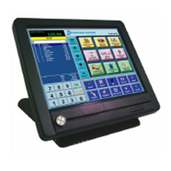
Page 9: Pos System Illustration
Chapter 1 Introduction 1-2. POS SYSTEM ILLUSTRATION ′ Page: 1-3 PS8852 USER S MANUAL... -
Page 10: System Specification
PC/AT Compatible, with mini DIN connecter on rear panel MOUSE CONNECTOR : PS/2 Mouse, with mini DIN connecter on rear panel IDE INTERFACE : Enhance DMA-33/66/100, 1 Channel. 44pin on-board connector for 2.5” slim type. ′ Page: 1-4 PS8852 USER S MANUAL... - Page 11 SOUND FUNCTION : Realtek ALC2002A, AC97 Codec. Support Line-out(speaker) and MIC-in on rear panel VGA FUNCTION : Built-in North Bridge Support simultaneous display of CRT and LCD. BOARD DIMENSION : Prox-8852: 222 x 202 mm ′ Page: 1-5 PS8852 USER S MANUAL...
- Page 12 CARD READER (OPTIONAL) TYPE MSR (ISO1,2,3 + JIS II) Function Read Interface Keyboard Wedge Speed MSR:5~45 inch/sec (12.7~114.3 cm/sec) Lift Cycle Megnetic head life is over 1,000,000 cycles Voltage Standard ISO 7811 & ISO 7816 ′ Page: 1-6 PS8852 USER S MANUAL...
-
Page 13: Safety Precautions
Avoid exposure to sunlight for a long period of time (for example in a closed car in summer time. Also avoid the system from any heating device.). Or do not use PS8852 when it‘s been left outdoors in a cold winter day. - Page 14 Avoid moving the system rapidly from a hot place to a cold place or vice versa because condensation may come from inside of the system. f. Place PS8852 against strong vibrations, which may cause hard disk failure. g. Do not place the system too close to any radio active device. Radio- active device may cause interference.
-
Page 15: Chapter 2 System Configuration
CHAPTER SYSTEM CONFIGURATION Helpful information that describes the jumper & connector settings, and component locations. Section includes: Component Locations Configuration and Jumper settings Jumper & Connector Quick Reference Table Connector Pin Assignments Page 2-1... -
Page 16: Component Locations
Chapter 2 Hardware Configuration 2-1. COMPONENT LOCATIONS PS8852 Connector, Jumper and Component locations Page: 2-2 ’ PS8852 USER S MANUAL... -
Page 17: How To Set The Jumpers
PIN1 & PIN2 to create one setting and shorting. You can either connect PIN2 & PIN3 to create another setting. The same jumper diagrams are applied all through this manual. The figure below shows what the manual diagrams look and what they represent. Page: 2-3 ’ PS8852 USER S MANUAL... - Page 18 Chapter 2 Hardware Configuration JUMPER DIAGRAMS JUMPER SETTINGS Page: 2-4 ’ PS8852 USER S MANUAL...
-
Page 19: Com Port Connector
Hard Disk Drive Connector IDE1 2-22 Mini-PCI Connector MINI-PCI1 2-23 Clear CMOS Data Selection JP_CMOS1 2-24 CPU FSB (Front Side Bus) Selection 2-25 CPU Host Clock Selection 2-25 LVDS Panel 3.3V/5V Voltage Selection 2-26 Page: 2-5 ’ PS8852 USER S MANUAL... -
Page 20: Com Port Connector
TXD1 DTR1 DSR1 RTS1 CTS1 RI / 5V / 12V selectable COM2 : COM2 Connector The COM2 Connector assignments are as follows : ASSIGNMENT DCD2 RXD2 TXD2 DTR2 DSR2 RTS2 CTS2 RI/5V/12V selectable Page: 2-6 ’ PS8852 USER S MANUAL... - Page 21 The pin assignments are as follows : ASSIGNMENT DCD4 RXD4 TXD4 DTR4 DSR4 RTS4 CTS4 RI/5V/12V selectable All COM port is selectable for RI, 5V(VCC) or 12V(VCC12). For more information, please refer to our “COM RI and Voltage Selection”. Page: 2-7 ’ PS8852 USER S MANUAL...
-
Page 22: Com1 Ri And Voltage Selection
Chapter 2 Hardware Configuration 2-5. COM1 RI & VOLTAGE SELECTION JP_COM1 : COM1 RI & Voltage Selection The selections are as follows: SELECTION JUMPER JUMPER SETTINGS ILLUSTRATION ***Manufacturing Default – RI. Page: 2-8 ’ PS8852 USER S MANUAL... -
Page 23: Com2 Ri And Voltage Selection
Chapter 2 Hardware Configuration 2-6. COM2 RI & VOLTAGE SELECTION JP_COM2 : COM2 RI & Voltage Selection The selections are as follows: SELECTION JUMPER JUMPER SETTINGS ILLUSTRATION ***Manufacturing Default – RI. Page: 2-9 ’ PS8852 USER S MANUAL... -
Page 24: Com3 Ri And Voltage Selection
Chapter 2 Hardware Configuration 2-7. COM3 RI & VOLTAGE SELECTION JP_COM3 : COM3 RI & Voltage Selection The selections are as follows: SELECTION JUMPER JUMPER SETTINGS ILLUSTRATION ***Manufacturing Default – RI. Page: 2-10 ’ PS8852 USER S MANUAL... -
Page 25: Com4 Ri And Voltage Selection
Chapter 2 Hardware Configuration 2-8. COM4 RI & VOLTAGE SELECTION JP_COM4 : COM4 RI & Voltage Selection The selections are as follows: SELECTION JUMPER JUMPER SETTINGS ILLUSTRATION ***Original Manufacturing Default – RI. Page: 2-11 ’ PS8852 USER S MANUAL... -
Page 26: Cash Drawer Connector
Write “04h” to I/O Port “0x40B9”h Detect Drawer Status Read I/O “0x40B9”h Definition (BIT7 BIT6 BIT5 BIT4 BIT3 BIT2 BIT1 BIT0) Check whether BIT3=1 1: the drawer was OPENED 0: the drawer was CLOSED Page: 2-12 ’ PS8852 USER S MANUAL... -
Page 27: Cash Drawer Power Selection
Chapter 2 Hardware Configuration 2-10. CASH DRAWER POWER SELECTION JCASH1 : Cash Drawer Power Selection The jumper settings are as follows : SELECTION JUMPER SETTINGS JUMPER ILLUSTRATION (default) *** Manufactory default --- 12V(VCC12). Page: 2-13 ’ PS8852 USER S MANUAL... -
Page 28: Dc Jack
2-12. PRINTER CONNECTOR JPRNT1 : Printer Connector The Printer Connector assignments are as follows : ASSIGNMENT ASSIGNMENT STBJ ALFJ PDR0 ERRJ PDR1 PAR_INITJ PDR2 SLCTINJ PDR3 PDR4 PDR5 PDR6 PDR7 ACKJ BUSY SLCTJ Page: 2-14 ’ PS8852 USER S MANUAL... -
Page 29: Vga Connector
2-14. KEYBOARD AND PS/2 MOUSE CONNECTOR KB-MS1 : PC/AT Keyboard and PS/2 Mouse Connector The pin assignments are as follows : ASSIGNMENT PIN ASSIGNMENT KB DATA MS DATA 5VSB 5VSB KB CLK MS CLK Page: 2-15 ’ PS8852 USER S MANUAL... -
Page 30: Lan & Usb Connector
Green Color On LAN switch/hub connected No LAN switch/hub connected Right side LED : Yellow Color Blinking LAN Message Active No LAN Message Active USB1and 2 : ASSIGNMENT USBV0 USB0N USB0P USBV1 USB1N USB1P Page: 2-16 ’ PS8852 USER S MANUAL... -
Page 31: Audio Connector
JPWR_SW1 : Power Switch Connector The pin assignment is as follows : ASSIGNMENT 3VSB PWB_SIOJ 2-18. RESET SWITCH CONNECTOR JRST_SW1 : RESET Switch Connector The pin assignment is as follows : ASSIGNMENT RST_SW Page: 2-17 ’ PS8852 USER S MANUAL... -
Page 32: Lvds/ Usb/ Inverter Connector
The pin assignments are as follows : ASSIGNMENT ASSIGNMENT LVDS_VCC LVDS_VCC LVDS_VCC LVDS_CLKBN LVDS_CLKBP LVDS_YBP2 LVDS_YBN2 LVDS_YBN1 LVDS_YBP1 LVDS_YBP0 LVDS_YBN0 LVDS_YBP3 LVDS_YBN3 LVDS_CLKAN LVDS_CLKAP LVDS_YAP2 LVDS_YAN2 LVDS_YAN1 LVDS_YAP1 LVDS_YAP0 LVDS_YAN0 LVDS_YAP3 LVDS_YAN3 USB_R4N USB_R4P USBV4 USBV4 VCC_BKLTEN VCC12_INV VCC12_INV Page: 2-18 ’ PS8852 USER S MANUAL... -
Page 33: Usb/Com Port/ Msr/ Line-Out Connector
JFP2 : USB/ COM Port/ MSR/ Line-Out Connector The pin assignments are as follows : ASSIGNMENT ASSIGNMENT USBV5 USBV5 USB_R5N USB_R5P DCD3 RXD3 TXD3 DTR3 DSR3 RTS3 CTS3 RI_SEL RI_SEL KCLK_KB KCLK_C KDAT_KB KDAT_C VCC12 VCC12 LINE_OUT_R LINE_OUT_L Page: 2-19 ’ PS8852 USER S MANUAL... -
Page 34: Fan Connector
The pin assignments are as follows : ASSIGNMENT 12V(VCC12) Fan Detect(Fan2) 2-22. SERIAL ATA CONNECTOR (WITH RAID FUNCTION) SATA1 : Serial ATA Connector The pin assignment is as follows : ASSIGNMENT TXP1 TXN1 RXN1 RXP1 Page: 2-20 ’ PS8852 USER S MANUAL... -
Page 35: Sata Power Connector
2-23. SATA POWER CONNECTOR JPWR_4P1 : SATA Power Connector The pin assignment is as follows : ASSIGNMENT 5V(VCC) 12V(VCC12) 2-24. 24V-OUT POWER CONNECTOR J24VOUT1 : 24V Power Connector The selections are as follows: ASSIGNMENT Page: 2-21 ’ PS8852 USER S MANUAL... -
Page 36: Hard Disk Drive Connector
PDD7 PDD8 PDD6 PDD9 PDD5 PDD10 PDD4 PDD11 PDD3 PDD12 PDD2 PDD13 PDD1 PDD14 PDD0 PDD15 PDREQ PDIOWJ PDIORJ PDIORDY PULL LOW PDDACKJ IRQ14 PDA1 PD66_DETECT PDA0 PDA2 PDCSJ1 PDCSJ3 IDEACTPJ 5V(VCC) 5V(VCC) Page: 2-22 ’ PS8852 USER S MANUAL... -
Page 37: Mini-Pci Connector
P_DEVSELJ P_AD3 P_CBEJ1 P_AD0 VCC3_3 P_AD21 P_PREQJ0 P_AD22 P_AD14 P_PGNTJ0 P_AD19 P_AD15 P_AD1 VCC3_3 P_AD20 P_AD13 P_AD31 P_PAR P_AD12 PCI_PMEJ P_AD17 P_AD11 P_AD29 P_AD18 P_AD10 M66EN P_CBEJ2 105~113 P_AD16 P_AD30 P_IRDYJ P_AD9 115~124 Page: 2-23 ’ PS8852 USER S MANUAL... -
Page 38: Clear Cmos Data Selection
To clear CMOS data, user must power-off the computer and set the jumper to “Clear CMOS” as illustrated above. After five to six seconds, set the jumper back to “Normal” and power-on the computer. Page: 2-24 ’ PS8852 USER S MANUAL... -
Page 39: Cpu Fsb (Front Side Bus) Selection
JP2 : CPU Host Clock Selection The selections are as follows : JUMPER SETTING JUMPER FUNCTION (pin closed) ILLUSTRATION Host Clock = 100 (default) *** Manufacturing Default is set as Host Clock = 100MHz.. Page: 2-25 ’ PS8852 USER S MANUAL... -
Page 40: Lvds Panel 3.3V/5V Voltage Selection
2-30. LVDS PANEL 3.3V/5V VOLTAGE SELECTION JP4 : LVDS Panel 3.3V/5V Voltage Selection The selections are as follows: JUMPER JUMPER SETTING SELECTION ILLUSTRATION (pin closed) 3.3V (default) ***Manufacturing Default is set as 3.3V. Page: 2-26 ’ PS8852 USER S MANUAL... -
Page 41: Chapter 3 Software Utilities
CHAPTER SOFTWARE UTILITIES This chapter comprises the detailed information of VGA driver, LAN driver, sound driver, Intel Chipset Software Utility driver, Touchscreen driver and Flash BIOS update. It also describes how to install the watchdog timer configuration. Section includes: VGA Driver Utility Flash BIOS Update LAN Driver Utility Sound Driver Utility... -
Page 42: Introduction
Chapter 3 Software Configuration 3-1. INTRODUCTION Enclosed with our PS8852 package is our driver utility, which may comes in a form of a CD ROM disc or floppy diskettes. For CD ROM disc user, you will only need some of the files contained in the CD ROM disc, please kindly... -
Page 43: Vga Driver Utility
Chapter 3 Software Configuration 3-2. VGA DRIVER UTILITY The VGA interface embedded with our PS8852 can support a wide range of display mode, such as SVGA, STN, TFT ..etc. You can display CRT, LVDS and PanelLink simultaneously with the same mode. -
Page 44: Flash Bios Update
Utility Disk for system BIOS and VGA BIOS update. 3-3-2. To update VGA BIOS for LCD Flat Panel Display: As PS8852 user, you have to update the VGA BIOS for your specific LCD flat panel you are going to use. For doing this, you need two files. - Page 45 File Name to Program: S75xxxxx.bin Checksum: XXXXX Reset System or Power off to accomplish update process! F1: Reset F10: Exit Please reset or power off the system, and then the Flash BIOS is fully implemented. ′ Page:3-5 PS8852 USER S MANUAL...
-
Page 46: Lan Driver Utility
Chapter 3 Software Configuration 3-4. LAN DRIVER UTILITY 3-4-1. Introduction PS8852 POS system is enhanced with LAN function that can support various network adapters. Installation programs for LAN drivers are listed as follows: 3-4-2. Installation Procedures of LAN Driver 1. Install LAN Driver to Windows 98SE/2000/XP/WEPOS Executing Windows 98SE/Windows 2000/ Windows XP, and WEPOS, it will auto-detect your system configuration and find the adapter hardware. -
Page 47: Sound Driver Utility
Windows 98SEE, Windows 2000, Windows XP, and WEPOS. Below, you will find the content of the Sound driver : 3-5-2. Installation Procedure To install, kindly refer to the readme.txt file on the Driver Disc (:\Sound\Realtek\Readme.txt). ′ Page:3-7 PS8852 USER S MANUAL... -
Page 48: Intel Chipset Software Installation Utility
3. Click Setup.exe file for utility installation. 4. Follow the instructions on the screen to complete the installation. 5. Once installation is completed, shut down the system and restart it in order to complete the changes. ′ Page:3-8 PS8852 USER S MANUAL... -
Page 49: Usb2.0 Software Installation Utility
5. Double Click “USB Root Hub”. 6. Select “Driver”. 7. Click “Install” to install the driver. 8. Follow the instructions on the screen to complete the installation. 9. Click “Finish” after the driver installation is complete. ′ Page:3-9 PS8852 USER S MANUAL... -
Page 50: Touchscreen Driver Utility
2. Under Windows 98SE/2000/XP/WEPOS system, go to the directory where Utility Disc is located. 3. Click “CIDTestAPSetup.exe” file for utility installation. 4. Follow the instructions on the screen to complete the installation. 5. Please to compare Driver CD\MSR_AP\ MSR_iButton_Configuration_Guide ′ Page:3-10 PS8852 USER S MANUAL... -
Page 51: Watchdog Timer Configuration
WDT_VAL to any other non-zero value will cause the WDT to reload and begin counting down from the value loaded. Setting the Register located on I/O address 0x867h and 0x868h as 00h to finish timer configuration. Example Program ′ Page:3-11 PS8852 USER S MANUAL... -
Page 52: Sata Introduction And Install
Before installing VASRAID 6153S into your existing system, please backup any important and necessary data. VASRAID 6153S is like any computer peripheral which is susceptible to static electricity. Be sure you are well grounded for the installation. ′ Page:3-12 PS8852 USER S MANUAL... - Page 53 Chapter 3 Software Configuration 2. Set the Environment PS8852 provides 2 modes for setting the SATA hard disk, they are RAIDm1 mode and ATA mode. 1. RAIDm1 mode After setting “RAIDm1 mode”, you can get real-time data protection for the SATA hard disk.
- Page 54 2. Changing original RAIDm1 mode to ATA mode If you have ever set the SATA hard disk as RAIDm1 mode previously, and now you would like to abort RAIDm1 real-time data protection feature to get ′ Page:3-14 PS8852 USER S MANUAL...
- Page 55 Step 3: Press the device number like ”1” which you would like to change. Step 4: Press “Y” to confirm to change RAIDm1 mode to ATA mode, then you will lose real-time data protection feature ′ Page:3-15 PS8852 USER S MANUAL...
- Page 56 The number shows the full capacity of the hard disk. Pressing <ESC> key to continue. Step 7: It is unnecessary to install the driver. Just using the original RAIDm1 driver you had installed previously then can work. ′ Page:3-16 PS8852 USER S MANUAL...
- Page 57 Windows operation systems. Please choose the below section and follow according to your environment. 3-1-1. Installing In Windows 2000 3-1-2. Installing In Windows XP 3-1-3. Installing In Windows XP x64 ′ Page:3-17 PS8852 USER S MANUAL...
- Page 58 Press “F6” key when Windows setup appears Step 2: Press “S” key to continue in Windows setup Screen Step 3: Insert VASRAID 6153S driver diskette into the drive A, and press “Enter” to continue. ′ Page:3-18 PS8852 USER S MANUAL...
- Page 59 Controller Windows 2000 Driver” item. Step 5: As “Windows 2000 Setup” screen appears, press “Enter” to continue. Step 6: As the right screen appears, press “Enter” to create all HDD capacity for RAIDm1 use. ′ Page:3-19 PS8852 USER S MANUAL...
- Page 60 ” VASSTEK VASRAID 6153S PCI SATA Storage Controller” should appear. 3-1-2. Installing in Windows XP Step 1: Press “F6” key when Windows setup appears. Step 2: Press “S” key to continue in Windows setup screen. ′ Page:3-20 PS8852 USER S MANUAL...
- Page 61 Choose “VASRAID 6153S PCI SATA Storage Controller Windows XP Driver” item. Step 5: As “Windows Setup” screen appears, press “Enter” to continue. Step 6: As the right screen appears, press “Enter” to create all HDD capacity for RAIDm1 use. ′ Page:3-21 PS8852 USER S MANUAL...
- Page 62 “Properties”. b. Choose the “Hardware” tab, then click the “Device Manager” tab. c. Double click “SCSI and RAID Controllers”, then ” VASSTEK VASRAID 6153S PCI SATA Storage Controller” should appear. ′ Page:3-22 PS8852 USER S MANUAL...
- Page 63 Press “F6” key when Windows setup appears. Step 2: Press “S” key to continue in Windows setup screen. Step 3: Insert VASRAID 6153S driver diskette into the drive A, and press “Enter” to continue. ′ Page:3-23 PS8852 USER S MANUAL...
- Page 64 As “Windows Setup” screen appears, press “Enter” to continue Step 6: As the right screen appears, press “Enter” to create all HDD capacity for RAIDm1 use Step 7: Press “Yes” button in “Software Installation” screen to continue installation. ′ Page:3-24 PS8852 USER S MANUAL...
- Page 65 “Properties”. b. Choose the “Hardware” tab, then click the “Device Manager” tab. c. Double click “SCSI and RAID Controllers”, Then ” VASSTEK VASRAID 6153S PCI SATA Storage Controller” should appear. ′ Page:3-25 PS8852 USER S MANUAL...
- Page 66 After you set RAIDm1 BIOS and installing the driver, you could follow below steps for installing “Vadi” utility continuously. Installing Steps: Step 1: Insert PS8852 driver utilities CD in the CD-ROM drive. Step 2: If your system is Windows 2000or Windows XP, please enter D:\Driver\SATA\Vadi UTILITY\Vadi\x32 directory and double click “VadiRun.exe”...
- Page 67 Accumulated Read error: It shows the number of accumulating read errors for the RAIDm1 hard disk from you start using Vadi utility to this time. It helps you to realize the status of your hard disk and help you to take the ′ Page:3-27 PS8852 USER S MANUAL...
- Page 68 “Check Bad sectors history”: Getting the history of happening time and LBA address which bad sectors have ever occurred as accessing the file which were read from the backup area. ′ Page:3-28 PS8852 USER S MANUAL...
- Page 69 Chapter 3 Software Configuration 4-4. Uninstall Vadi utility Step 1: Insert PS8852 driver utilities CD in the CD-ROM drive. Step 2: If your system is Windows 2000 or Windows XP, please enter D:\Driver\SATA\Vadi UTILITY\Vadi\x32 directory and double click “VadiRun.exe” file.
-
Page 70: Chapter 4 Award Bios Setup
CHAPTER AWARD BIOS SETUP This chapter shows how to set up the Award BIOS. Section includes: Introduction Entering Setup The Standard CMOS Features The Advanced BIOS Features The Advanced Chipset Features Integrated Peripherals Power Management Setup PNP/PCI Configuration PC Health Status Frequency Control Load Fail-Safe Defaults Load Optimized Defaults... - Page 71 4-1. INTRODUCTION This chapter will show you the function of the BIOS in managing the features of your system. The PS8852 15” POS Terminal is equipped with the BIOS for system chipset from Award Software Inc. This page briefly explains the function of the BIOS in managing the special features of your system.
-
Page 72: Load Optimized Defaults
You may use the cursor the up/down keys to highlight the individual menu items. As you highlight each item, a brief description of the highlighted selection will appear at the bottom of the screen. ′ Page: 4-3 PS8852 USER S MANUAL... - Page 73 < Hour >, < Minute >, and < Second >. Use 24 hour clock format, i.e., for PM numbers, add 12 to the hour. For example: 4: 30 P.M. You should enter the time as 16:30:00. ′ Page: 4-4 PS8852 USER S MANUAL...
- Page 74 Auto: The BIOS automatically determines the optimal mode. Normal: Maximum number of cylinders, heads, sectors supported are 1024, 16 and 63. Large: For drives that do not support LBA and have more than 1024 cylinders. ′ Page: 4-5 PS8852 USER S MANUAL...
- Page 75 BASE MEMORY: Displays the amount of conventional memory detected during boot up. EXTENDED MEMORY: Displays the amount of extended memory detected during boot up. TOTAL MEMORY: Displays the total memory available in the system. ′ Page: 4-6 PS8852 USER S MANUAL...
- Page 76 1024 65535 1023 1024 65535 1023 1024 65535 1023 1024 65535 1023 1024 65535 1023 65535 1023 65535 1024 65535 1023 1024 65535 1023 65535 65535 65335 AUTO Award Hard Disk Type Table ′ Page: 4-7 PS8852 USER S MANUAL...
-
Page 77: The Advanced Bios Features
If this function is enabled and someone attempt to write data into this area , BIOS will show a warning message on screen and alarm beep. CPU L1 & L2 CACHE: This item allows you to enable L1 & L2 cache. ′ Page: 4-8 PS8852 USER S MANUAL... - Page 78 This item sets the number of times a second to repeat a key stroke when you hold the key down. TYPEMATIC DELAY (MSEC): The item sets the delay time after the key is held down before it begins to repeat the keystroke. ′ Page: 4-9 PS8852 USER S MANUAL...
- Page 79 Do not type anything and just press <Enter>, it will disable security. Once the security is disabled, the system will boot and you can enter Setup freely. ′ Page: 4-10 PS8852 USER S MANUAL...
- Page 80 The default settings have been chosen because they provide the best opera- ting conditions for the system. The only time you might consider making any changes would be if you discovered that data was being lost while using your system. ′ Page: 4-11 PS8852 USER S MANUAL...
- Page 81 However, if any program writes to this memory area, a system error may result. On-Chip VGA To Enable/Disable the onboard display chip. Boot Display To select the boot-up display type. PCI SERR# NMI To Enable/Disable the PCI SERR# interrupt ′ Page: 4-12 PS8852 USER S MANUAL...
- Page 82 If bios setup menu item supports USB device boot, it will cause Win9x detects the same storages twice when the system is rebooted, and USB HDD will fail. Note: this cause just happen under Win9x, the phenomenon is a limitation. ′ Page: 4-13 PS8852 USER S MANUAL...
- Page 83 Ultra DMA/33 implementation is possible only if your IDE hard drive supports it and the operating environment includes a DMA driver (Windows 95 OSR2 or a third-party IDE bus master driver). If you ′ Page: 4-14 PS8852 USER S MANUAL...
- Page 84 3. USB Mouse Support Select Enabled if your system contains a Universal Serial Bus (USB) controller and you have a USB Mouse. Audio: AC97 This item allows you to enable/disable to support AC97 Audio. ′ Page: 4-15 PS8852 USER S MANUAL...
- Page 85 This item allows you to determine access onboard parallel port controller with which I/O address. 5. Parallel Port Mode Select an operating mode for the onboard parallel (printer) port. Select Normal, Compatible, or SPP unless you are certain your ′ Page: 4-16 PS8852 USER S MANUAL...
- Page 86 ONBOARD SERIAL PORT 3: ONBOARD SERIAL PORT 4: Select a logical COM port name and matching address for the third and forth serial ports. Select an address and corresponding interrupt for third and forth serial port. ′ Page: 4-17 PS8852 USER S MANUAL...
- Page 87 ACPI FUNCTION: Users are allowed to enable or disable the Advanced Configuration and Power Management (ACPI). POWER MANAGEMENT: This item allows you to select the Power Management mode. ′ Page: 4-18 PS8852 USER S MANUAL...
- Page 88 An input signal from PME on the PCI card awakens the system from a soft off state. RESUME BY ALARM: When Enabled, your can set the date and time at which the RTC (real-time clock) alarm awakens the system from Suspend mode. ′ Page: 4-19 PS8852 USER S MANUAL...
- Page 89 RESOURCE CONTROLLED BY: The Award Plug and Play Bios can automatically configure all of the booth and Plug and Play-compatible devices. However, this capability means ′ Page: 4-20 PS8852 USER S MANUAL...
- Page 90 F5: Previous Values F6:Fail-Safe Defaults F7:Optimized Defaults Descriptions on each item above are as follows: IRQ-n Assigned to: You may assign each system interrupt a type, depending on the type of device using the interrupt. ′ Page: 4-21 PS8852 USER S MANUAL...
- Page 91 LED while CPU is overheated. CURRENT CPU TEMPERATURE: This item shows you the current CPU temperature. CURRENT SYSTEM FAN SPEED: This item shows you the current System FAN speed. ′ Page: 4-22 PS8852 USER S MANUAL...
-
Page 92: Frequency Control
Enabling pulse spectrum spread modulation changes the extreme values from spikes to flat curves, thus reducing EMI. This benefit may in some cases be outweighed by problems with timing- critical devices such as a clock-sensitive SCSI device. ′ Page: 4-23 PS8852 USER S MANUAL... - Page 93 When you press <Enter> on this category, you get a confirmation dialog box with a message similar to the following: Load Optimized Defaults ( Y/N ) ? N Pressing "Y" loads the default values that are factory setting for optimal performance system operations. ′ Page: 4-24 PS8852 USER S MANUAL...
- Page 94 PASSWORD DISABLED!!! Press any key to continue... Press the < Enter > key again and the password will be disabled. Once the password is disabled, you can enter Setup freely. ′ Page: 4-25 PS8852 USER S MANUAL...
- Page 95 You may always call up the setup program at any time to adjust any of the individual items by pressing the <Del> key during boot up. ′ Page: 4-26 PS8852 USER S MANUAL...
- Page 96 ►Integrated Peripherals ►Power Management word Quit Without Saving (Y/N)? N ►PnP/PCI Configura etup ►PC Health Status Saving Esc : Quit ↑↓→← : Select Item F10 : Save & Exit Setup Abandon all Datas ′ Page: 4-27 PS8852 USER S MANUAL...
-
Page 97: Appendix A System Assembly
APPENDIX SYSTEM ASSEMBLY This appendix contain exploded diagram of the system. Section includes: Exploded Diagram for VFD Installation Exploded Diagram for MSR and HDD Installation Exploded Diagram for Hard Disk Drive Installation Exploded Diagram for LCD Panel Installation Exploded Diagram for RJ11 Installation Exploded Diagram for Stand and Front Panel Installation Exploded Diagram for Front Panel Installation Exploded Diagram for USB LED Installation... -
Page 98: Exploded Diagram For Vfd Installation
Appendix A System Assembly EXPLODED DIAGRAM FOR VFD INSTALLATION Diagram 1: ′ Page: A-2 PS8852 USER S MANUAL... - Page 99 Appendix A System Assembly Diagram 2: ′ Page: A-3 PS8852 USER S MANUAL...
- Page 100 Appendix A System Assembly Diagram 3: ′ Page: A-4 PS8852 USER S MANUAL...
- Page 101 Appendix A System Assembly Diagram 4: ′ Page: A-5 PS8852 USER S MANUAL...
- Page 102 Appendix A System Assembly Diagram 5: ′ Page: A-6 PS8852 USER S MANUAL...
-
Page 103: Exploded Diagram For Msr And Hdd Installation
Appendix A System Assembly EXPLODED DIAGRAM FOR MSR AND HDD INSTALLATION ′ Page: A-7 PS8852 USER S MANUAL... - Page 104 Appendix A System Assembly EXPLODED DIAGRAM FOR HARD DISK DRIVE INSTALLATION ′ Page: A-8 PS8852 USER S MANUAL...
- Page 105 Appendix A System Assembly EXPLODED DIAGRAM FOR LCD PANEL INSTALLATION ′ Page: A-9 PS8852 USER S MANUAL...
- Page 106 Appendix A System Assembly EXPLODED DIAGRAM FOR RJ11 INSTALLATION ′ Page: A-10 PS8852 USER S MANUAL...
- Page 107 Appendix A System Assembly EXPLODED DIAGRAM FOR STAND AND FRONT PANEL INSTALLATION ′ Page: A-11 PS8852 USER S MANUAL...
- Page 108 Appendix A System Assembly ′ Page: A-12 PS8852 USER S MANUAL...
- Page 109 Appendix A System Assembly EXPLODED DIAGRAM FOR FRONT PANEL INSTALLATION ′ Page: A-13 PS8852 USER S MANUAL...
- Page 110 Appendix A System Assembly EXPLODED DIAGRAM FOR USB LED INSTALLATION ′ Page: A-14 PS8852 USER S MANUAL...
- Page 111 Appendix A System Assembly EXPLODED DIAGRAM FOR BOTTOM COVER INSTALLATION ′ Page: A-15 PS8852 USER S MANUAL...
- Page 112 Appendix A System Assembly EXPLODED DIAGRAM FOR STAND INSTALLATION ′ Page: A-16 PS8852 USER S MANUAL...
- Page 113 Appendix A System Assembly ′ Page: A-17 PS8852 USER S MANUAL...
- Page 114 Appendix A System Assembly EXPLODED DIAGRAM FOR SYSTEM BOTTOM INSTALLATION ′ Page: A-18 PS8852 USER S MANUAL...
- Page 115 Appendix A System Assembly ′ Page: A-19 PS8852 USER S MANUAL...
- Page 116 APPENDIX TECHNICAL SUMMARY This section introduce you the maps concisely. Section includes: Block Diagram Interrupt Map RTC (Standard) RAM Bank Timer & DMA Channels Map I / O & Memory Map Page: B-1...
-
Page 117: Block Diagram
Appendix B Technical Summary BLOCK DIAGRAM ′ Page: B-2 PS8852 USER S MANUAL... -
Page 118: Interrupt Map
System TIMER interrupt from TIMER-0 Keyboard Cascade for IRQ 8-15 Serial port 2 Serial port 1 Parallel port 2 Floppy disk Parallel port 1 RTC Alarm clock IRQ2 Redir COM3 COM4 PS/2 Mouse Coprocessor IDE1 IDE2 ′ Page: B-3 PS8852 USER S MANUAL... -
Page 119: Rtc & Cmos Ram Map
Extension memory low byte Extension memory high byte Reserved for extension memory low byte Reserved for extension memory high byte Date Century byte Information Flag 34-3F Reserve 40-7f Reserved for Chipset Setting Data ′ Page: B-4 PS8852 USER S MANUAL... -
Page 120: Timer & Dma Channels Map
Timer Channel Map : Timer Channel Assignment System timer interrupt DRAM Refresh request Speaker tone generator DMA Channel Map : DMA Channel Assignment Available Available Floppy Available Cascade for DMA controller 1 Available Available Available ′ Page: B-5 PS8852 USER S MANUAL... -
Page 121: I/O & Memory Map
Parallel port-2 2B0-2DF Graphics adapter controller 2F8-2FF Serial port-2 360-36F Net work ports 378-37F Parallel port-1 3B0-3BF Monochrome & Printer adapter 3C0-3CF EGA adapter 3D0-3DF CGA adapter 3F0-3F7 Floppy disk controller 3F8-3FF Serial port-1 ′ Page: B-6 PS8852 USER S MANUAL...
Need help?
Do you have a question about the PS8852 and is the answer not in the manual?
Questions and answers