
Related Manuals for ThermoFisher Scientific QuantStudio 6 Pro


Summary of Contents for ThermoFisher Scientific QuantStudio 6 Pro
- Page 1 QuantStudio 6 Pro Real-Time PCR System ™ and QuantStudio 7 Pro Real-Time PCR ™ System USER GUIDE Publication Number MAN0018045 Revision L For Research Use Only. Not for use in diagnostic procedures.
- Page 2 Life Technologies Holdings Pte Ltd | Block 33 | Marsiling Industrial Estate Road 3 | #07-06, Singapore 739256 For descriptions of symbols on product labels or product documents, go to thermofisher.com/symbols-definition. Revision history: MAN0018045 L (English) Revision Date Description 7 May 2024 v1.8.1 or later Instructions were added to copy and delete sample setup files (“Manage sample setup files”...
- Page 3 Revision Date Description 23 February 2024 v1.8 or later The feature to manage settings for data export and data import was added (“Manage the settings for data • export and data import” page 214). The option to keep both data files or overwrite a data file was added when a data file is being transferred •...
- Page 4 Revision Date Description 27 October 2023 The information about monitoring instruments was updated (“Monitor instruments” page 228). • (contin ued) The processor requirements for the computer for the desktop software were updated. • The safety standards were updated (“Safety standards” page 254). •...
- Page 5 Revision Date Description 7 January 2020 v1.2.1 Added information about position to set up facial authentication and to sign in with facial authentication. • Added instructions to test the connection to the Thermo Fisher Connect Platform and to view the privacy •...
- Page 6 Revision Date Description 22 August 2019 Add a four-digit PIN when signing into the instrument for the first time using a Thermo Fisher – ™ (contin Connect Platform profile. ued) Add a four-digit PIN when linking a local instrument profile to a Thermo Fisher Connect Platform –...
-
Page 7: Table Of Contents
Contents ■ CHAPTER 1 Product information ..........17 Network and password security requirements . - Page 8 Contents System template file names ........... . . 37 System template file names for the 96-well 0.2-mL block .
- Page 9 Contents Set up or remove VeriFlex Zones ......... . . 63 ™...
- Page 10 Contents ■ CHAPTER 6 View and manage files ..........81 Manage plate files .
- Page 11 Contents Perform verification using RNase P plates ........111 Instrument verification description .
- Page 12 Contents ■ CHAPTER 9 Use the instrument with the Security, Auditing, and E‑signature (SAE) Administrator Console ........146 Overview of the SAE Administrator Console components .
- Page 13 Contents View the audit and e-signature records in the applications ......171 Audit records for actions ..........171 View audit records for objects for the QuantStudio Design and Analysis ™...
- Page 14 Contents Select a disk storage management mode ........195 Enable and edit automatic sign-out .
- Page 15 Contents ■ APPENDIX B Connect the instrument to a network ......223 Connect the computer to the instrument directly or to a LAN ..... . . 223 Connect the instrument to a wired network .
- Page 16 Contents Control and connection symbols ......... . . 248 Conformity symbols .
-
Page 17: Chapter 1 Product Information
Product information ■ Network and password security requirements ..........17 ■... -
Page 18: Instrument Hardware Description
Chapter 1 Product information Instrument hardware description Instrument hardware description Overview of the instrument The Applied Biosystems QuantStudio 6 Pro and 7 Pro Real-Time PCR Systems use fluorescent- ™ ™ based polymerase chain reaction (PCR) reagents to perform the following functions: • Quantitative detection of target nucleic acid sequences (targets) •... -
Page 19: Features Of Each Instrument
Chapter 1 Product information Instrument hardware description • Smart Help to request technical support or instrument service directly from the instrument • Barcode scanner for tracking plates or TaqMan Array Cards ™ Features of each instrument Feature QuantStudio 6 Pro System QuantStudio 7 Pro System ™... - Page 20 Chapter 1 Product information Instrument hardware description Wavelength (nm) Emission Spectra Filters x1-m1 x2-m2 x3-m3 x4-m4 x5-m5 x6-m6 x1-m1—FAM dye, SYBR Green x4-m4—JUN dye, ROX dye, Texas Red ™ ™ ™ ™ ™ ® x2-m2—VIC x5-m5—Cy 5, MUSTANG PURPLE ™ ™ x3-m3—ABY dye, NED dye, Cy ®...
-
Page 21: Overview Of Data Collection
Chapter 1 Product information Instrument hardware description Overview of data collection The instrument collects raw fluorescence data at different points during the PCR cycle, depending on the type of run performed. When you create a plate file, you can customize the optical filter channels through which the instrument collects data. -
Page 22: Autodelta Settings
Chapter 1 Product information Instrument hardware description Figure 1 Three VeriFlex Zones ™ Figure 2 Six VeriFlex Zones ™ Note: Plate files are not compatible between the QuantStudio 6 Pro System and the QuantStudio ™ ™ Pro System. For more information, see “Compatibility of plate files” page 32. -
Page 23: Parts Of The Instrument
Chapter 1 Product information Instrument hardware description Parts of the instrument Figure 3 Front of the instrument Cameras Proximity sensor Touchscreen Access door for block change Microphones Speakers USB port Drawer Indicator light QuantStudio 6 Pro Real-Time PCR System and QuantStudio 7 Pro Real-Time PCR System User Guide ™... - Page 24 Chapter 1 Product information Instrument hardware description Figure 4 Back of the instrument USB ports RS-232 port (service use only) Wi-Fi dongle port ON/OFF switch Ethernet port Power inlet receptacle Note: The instrument recognizes only one external storage device at a time for data transfer. The USB ports at the rear of the instrument can be used for external devices, for example, a mouse or a keyboard.
-
Page 25: Instrument Status Indicator
Chapter 1 Product information Hands-free features Instrument status indicator Indicator Instrument status Powered off Sleep mode Blue light changing brightness slowly Powering on Blue light changing brightness Standby Blue light moving inwards towards middle of instrument Drawer opening Blue light moving outwards towards side of instrument Drawer closing Blue light moving back and forth Block is being changed... -
Page 26: Indicators For The Hands-Free Features
Chapter 1 Product information Hands-free features Indicators for the hands-free features Indicators for facial authentication Display Status of facial authentication The Sign In screen displays Facial authentication for the instrument is enabled. • Facial authentication for the instrument is disabled. The Sign In screen does not display •... -
Page 27: Software Description
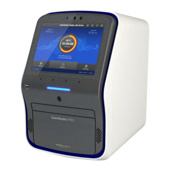
Chapter 1 Product information Software description Software description Parts of the home screen Figure 5 Home screen Instrument name Block installed Instrument calendar Current user Microphone Connectivity icons Help Buttons to access plate files Eject Instrument settings Status dial Table 1 Parts of the home screen Element of the Function home screen... - Page 28 Chapter 1 Product information Software description Table 1 Parts of the home screen (continued) Element of the Function home screen • When the instrument is not in use—Displays Set up run. Status dial • When the instrument is in use—Displays the sample block temperature, the elapsed run time, and the run status.
-
Page 29: Thermo Fisher
Chapter 1 Product information Software description Thermo Fisher Connect Platform definitions ™ The terms Connect, Cloud, Thermo Fisher Connect, Thermo Fisher Cloud, and Thermo Fisher Connect Platform are used interchangeably on the instrument touchscreen. The terms Thermo Fisher Connect ™ Platform and Connect are used in this document. The following icons are used interchangeably on the instrument touchscreen: •... -
Page 30: Overview Of File Locations And Files
Chapter 1 Product information Software description (continued) Thermo Fisher ™ Feature Instrument Desktop Connect Platform Check calibration status Analyze and export results View analysis of results — Set calibration reminders — Review exported calibration or RNase P verification results — (RNase P only) Overview of file locations and files Note: The term plate file is applicable to both plates and TaqMan Array Cards. - Page 31 Chapter 1 Product information Software description (continued) File location Description and function • This location is only available to a user who is signed in. Guest users cannot access this My instrument location to retrieve plate files or save data files. • This location is specific to a user. Files are not accessible to any other users, except for administrators.
- Page 32 Chapter 1 Product information Software description (continued) Item Description and function Supported in • A file that has been saved from a system template. • Instrument Plate File • Can be edited and saved. • Desktop From • Can be edited and saved as a separate plate file. •...
-
Page 33: Components Of The Files
Chapter 1 Product information Software description Components of the files Thermo Fisher Connect ™ Component Instrument Desktop Platform • Data file name • Experiment file name Properties • Reagent information • Plate barcode or TaqMan Array Card barcode ™ – Name • User name –... -
Page 34: Third-Party Software
Chapter 1 Product information Types of runs Third-party software Before installing third-party software on the computer running the desktop software, confirm that the third-party software will not do the following: • Restrict Ethernet communication. • Interfere with instrument or computer operation. Network connection options You can connect an instrument to a network or computer in the configurations listed below. -
Page 35: Relative Standard Curve Run
Chapter 1 Product information Types of runs Relative standard curve run A relative standard curve runs determines the relative target quantity in samples. 1. The software measures amplification of the target of interest and of an endogenous control target in a standard dilution series, in a reference (calibrator) sample, and in test samples. The endogenous control is a target that is expressed equally in all samples;... -
Page 36: Genotyping Run
Chapter 1 Product information Types of runs Genotyping run A genotyping runs detects the single nucleotide polymorphism (SNP) variants of a target nucleic acid sequence. Genotyping runs use preformulated TaqMan SNP Genotyping Assays that include the following ™ components: • Two sequence-specific primers for amplification of sequences containing the SNP of interest •... -
Page 37: System Template File Names
Chapter 1 Product information System template file names System template file names The first part of the file name varies, based on the instrument (QuantStudio 6 Pro System or ™ QuantStudio 7 Pro System). ™ The instrument will display the system templates applicable to the block that is installed. System template file names for the 96-well 0.2-mL block System template name Run type... -
Page 38: System Template File Names For The 96-Well 0.1-Ml Block
Chapter 1 Product information System template file names (continued) System template name Run type • Comparative C QS7Pro-96-Well-0-2ml_RQ_Std.edt • 96-well, 0.2-mL Standard plate • Standard cycling mode • Relative standard curve run QS7Pro-96-Well-0-2ml_RSC_Fast.edt • 96-well, 0.2-mL Standard plate • Fast cycling mode •... - Page 39 Chapter 1 Product information System template file names (continued) System template name Run type • Presence/absence run QS7Pro-96-Well-0-1ml_PA_Fast.edt • 96-well, 0.1-mL Standard plate • Fast cycling mode • Presence/absence run QS7Pro-96-Well-0-1ml_PA_Std.edt • 96-well, 0.1-mL Standard plate • Standard cycling mode • Melt curve run (with PCR stage) QS7Pro-96-Well-0-1ml_PCR_Melt_Fast.edt •...
-
Page 40: System Template File Names For The 384-Well Block
Chapter 1 Product information System template file names System template file names for the 384-well block System template name Run type • Genotyping run QS7Pro-384-Well-GT-Fast.edt • 384-well plate • Fast cycling mode • Genotyping run QS7Pro-384-Well-GT-Std.edt • 384-well plate • Standard cycling mode •... -
Page 41: System Template File Names For The Taqman
Chapter 1 Product information System template file names (continued) System template name Run type • Relative standard curve run QS7Pro-384-Well-RSC-Fast.edt • 384-well plate • Fast cycling mode • Relative standard curve run QS7Pro-384-Well-RSC-Std.edt • 384-well plate • Standard cycling mode • Standard curve run QS7Pro-384-Well-SC-Fast.edt •... - Page 42 Chapter 1 Product information System template file names (continued) System template name Run type • Standard curve run QS7Pro-TAC-SC-Std.edt • TaqMan Array Card ™ • Standard cycling mode • Comparative C run with melt curve QS7Pro-TAC-RQ-Melt-Fast.edt • TaqMan Array Card ™ • Fast cycling mode •...
-
Page 43: Workflow
Chapter 1 Product information Workflow Workflow Sign in to your instrument profile or your Thermo Fisher Connect Platform account ™ (PIN or facial authentication) ▼ Open a plate file (System template or saved plate file) ▼ (Optional) Edit the plate file ▼ Load the plate into the instrument ▼... -
Page 44: Chapter 2 Get Started
Get started ■ Precautions for use ..............44 ■... -
Page 45: Installation And Instrument Verification
Chapter 2 Get started Installation and instrument verification Installation and instrument verification The instrument is installed by a representative from Thermo Fisher Scientific. The following tasks will be performed during the installation process: • Unpack the instrument and the computer • Install the instrument and the computer •... -
Page 46: Use The Instrument As A Guest
Chapter 2 Get started Overview of guest access Use the instrument as a guest If the Guest button is not visible on the Sign In screen, guest access has been disabled. An administrator must enable guest access (see “Require sign-in” page 131). Guest button In the Sign-In screen, tap Guest. -
Page 47: Power On The Instrument
Chapter 2 Get started Power on the instrument Power on the instrument If left unattended, the instrument automatically enters sleep mode to conserve power. The default time that an instrument is inactive before going into sleep mode is 15 minutes. 1. Tap anywhere on the touchscreen to determine if the instrument is in sleep mode. If the screen becomes active, the instrument is already powered on. -
Page 48: Sign In
Chapter 2 Get started Sign in Sign in Sign in with a PIN Create an instrument profile before signing into the instrument (see “Create a new local instrument profile” on page 136 and “Link the instrument to your Thermo Fisher Connect Platform account” ™... -
Page 49: Enable Or Disable The Microphone
Chapter 2 Get started Enable or disable the microphone Enable or disable the microphone The microphone can be disabled if the voice command function is available. A blue microphone icon indicates that the voice command function is available. The microphone cannot be manually disabled if the voice command function is already not available. A gray microphone icon indicates that the voice command function is unavailable. -
Page 50: Sign Out
Chapter 2 Get started Sign out (continued) Voice command Instrument audio output Instrument action If the instrument has a block installed, the Change Block screen is displayed. Change Block — If there is no block in the instrument, the Install Block screen is displayed. Instrument —... -
Page 51: Chapter 3 Create And Run Plates On The Instrument
Create and run plates on the instrument ■ Options to run a plate ..............51 ■... - Page 52 Chapter 3 Create and run plates on the instrument Options to run a plate • Templates • Connect Note: You must be signed in with a Thermo Fisher Connect Platform account. ™ • Network Drive • USB Drive 3. Tap the template file name in the right column. The Plate Properties screen is displayed.
-
Page 53: Repeat The Last Run
Chapter 3 Create and run plates on the instrument Options to run a plate The status dial is displayed. The status dial contains the following information: • The block temperature • The elapsed time of the run • The status of the run Figure 7 Home screen during a run For options during a run, see Chapter 5, “Options for a run”. -
Page 54: Overview Of Customized Data Export
Chapter 3 Create and run plates on the instrument Overview of customized data export • This instrument Note: This option is not available if you are using the instrument as a guest. You must be signed in. The connection status of each location is displayed. If the connection between the instrument and the location that was selected to save the data file is interrupted, the instrument completes the run. -
Page 55: (Optional) Scan A Barcode Using A Barcode Scanner
Chapter 3 Create and run plates on the instrument (Optional) Scan a barcode using a barcode scanner (Optional) Scan a barcode using a barcode scanner The instrument is compatible with an optional Handheld Barcode Scanner (Cat. No. 4488442, purchased separately). The barcode scanner reads Code 128 (alphanumeric), which supports 128 ASCII character barcodes. -
Page 56: Load A Taqman ™ Array Card Into The Instrument
Chapter 3 Create and run plates on the instrument Load a TaqMan Array Card into the instrument ™ Load a TaqMan Array Card into the instrument ™ IMPORTANT! The instrument should be used by trained operators who have been warned of the moving parts hazard. - Page 57 Chapter 3 Create and run plates on the instrument Unload a plate or a TaqMan Array Card from the instrument ™ The status dial displays Run complete when the run is finished. If the automatic sign-out feature is enabled and the set time has elapsed, the instrument will display the Sign In screen. 1.
-
Page 58: Chapter 4 Edit A Plate Before Starting A Run
Edit a plate before starting a run ■ Overview of a template file with restricted editing ........58 ■... -
Page 59: Options To Edit The Properties Of A Plate File
Chapter 4 Edit a plate before starting a run Options to edit the properties of a plate file Options to edit the properties of a plate file The following files can be edited: • A system template (see “Create and run a plate from a system template or a saved plate file” page 51) A system template that is edited must be saved as a plate file. -
Page 60: Import An Auto Export Setting
Chapter 4 Edit a plate before starting a run Options to edit the method of a plate file Import an auto export setting The export settings can be customized. For more information about the export settings, see “Overview of customized data export” page 54. -
Page 61: Method Elements
Chapter 4 Edit a plate before starting a run Options to edit the method of a plate file • VeriFlex Zones (see page 63) ™ • Auto Delta (see page 65) • Ramp rates (see page 66) • Pauses (see page 66) Method elements Method tab Number of cycles for the stage Heated cover temperature Temperature for the step... -
Page 62: Add Or Remove Steps
Chapter 4 Edit a plate before starting a run Options to edit the method of a plate file 5. In the Save Template screen, select a storage location for the plate file, then tap Done. A confirmation is displayed. 6. Tap Close. Add or remove steps Add a PCR step or remove a PCR step. -
Page 63: Add Or Remove Data Collection Locations
Chapter 4 Edit a plate before starting a run Options to edit the method of a plate file Add or remove data collection locations 1. In the Method tab, tap Edit4Advanced4Data collection location. Note: Use to navigate through the method if it is not all displayed. 2. - Page 64 Chapter 4 Edit a plate before starting a run Options to edit the method of a plate file Figure 8 VeriFlex Zones and Auto Delta settings ™ VeriFlex Zones is selected ™ 2. Tap the temperature field in the appropriate VeriFlex Zone. ™ 3. Enter a temperature, then tap Enter. The temperatures in adjacent zones must have a difference of ≤5°C.
-
Page 65: Set Up Or Remove The Auto Delta Feature
Chapter 4 Edit a plate before starting a run Options to edit the method of a plate file Set up or remove the Auto Delta feature Note: The Auto Delta feature is only available in the PCR stage. 1. In the Method tab, tap Edit4Advanced4VeriFlex Zones / Auto Delta. -
Page 66: Configure Ramp Rates
Chapter 4 Edit a plate before starting a run Options to edit the well details of a plate file Configure ramp rates The ramp rate is how quickly the temperature changes from one stage or step to another stage or step. The maximum ramp rate for the instrument depends on the block type. 1. -
Page 67: Options To View A Plate Layout
Chapter 4 Edit a plate before starting a run Options to edit the well details of a plate file The following items can be edited in the Plate tab: • Sample name and sample type (see “Assign or edit a well for a plate” on page 69 and “Assign or edit a well for a TaqMan... - Page 68 Chapter 4 Edit a plate before starting a run Options to edit the well details of a plate file Select all button Plate view button Well table view button Color by dropdown list View a 384-well plate The Plate tab displays a 384-well plate if the 384-well block is installed. The plate can be edited in the 384-well view.
-
Page 69: Assign Or Edit A Well For A Plate
Chapter 4 Edit a plate before starting a run Options to edit the well details of a plate file If you selected a full row or column in the 96-well view, only the set of wells that was visible in the 96-well view is selected. The full row or column of the 384-well plate is not selected. 3. -
Page 70: Assign Or Edit A Well For A Taqman ™ Array Card
Chapter 4 Edit a plate before starting a run Options to edit the well details of a plate file 5. Tap Target/SNP, then select Target or Assay from the dropdown list. 6. Tap a row in the table, then tap Done. Add a target or an assay 1. -
Page 71: Apply The Reagents To A Plate
Chapter 4 Edit a plate before starting a run Options to edit the well details of a plate file 3. Tap a row in the table, then enter the information. • Reagent name • SKU (Part number) • Reagent type • Expiration date •... -
Page 72: Add Or Edit The Reagent Details For A Taqman ™ Array Card
Chapter 4 Edit a plate before starting a run Options to edit the well details of a plate file 4. Tap a row in the table, then delete the information in each field. • Reagent name • SKU (Part number) • Reagent type •... -
Page 73: Import An Assay Information File (Aif)
Chapter 4 Edit a plate before starting a run Options to edit the well details of a plate file The passive reference dye is displayed under the plate diagram. Import an assay information file (AIF) The assay information file is provided in TXT format and/or XML and HTML format, depending on the product line and order date. -
Page 74: Screens Available During A Run
Options for a run ■ Screens available during a run ............74 ■... -
Page 75: Chapter 5 Options For A Run
Chapter 5 Options for a run Edit a plate file during a run Figure 10 Home screen during a run Arrow Actions menu Edit a plate file during a run The targets and samples can be added or edited after a run has started. The method cannot be edited after a run has started. -
Page 76: Pause An Instrument Run
Chapter 5 Options for a run Pause an instrument run Pause an instrument run Pause a run to add reagents to the plate or to edit the number of cycles. 1. In the home screen during a run, tap (Actions). See Figure 10 page 75. -
Page 77: View The Method During A Run
Chapter 5 Options for a run View the method during a run View the method during a run 1. In the home screen during a run, swipe left once or tap the right arrow ( ) once. Start time Method, including the current stage End time Time remaining 2. -
Page 78: Adjust The Display Of Real-Time Plots During A Run
Chapter 5 Options for a run View the time remaining during a run 2. (Optional) Tap the dropdown list then select the view for the plot. • Linear • Log 10 3. (Optional) Tap Actions4Analyze amp plots. 4. (Optional) Tap Actions4View well details to see the amplification for a specific well. 5. -
Page 79: Unlock The Touchscreen During A Run
Chapter 5 Options for a run Unlock the touchscreen during a run Unlock the touchscreen during a run The touchscreen can be unlocked by the user who locked it or an administrator. The touchscreen automatically unlocks when the run is complete. 1. Tap anywhere on the touchscreen. 2. - Page 80 Chapter 5 Options for a run Instrument Schedule 3. Tap the reservation. The Edit Reservation screen is displayed. 4. Tap Cancel Reservation, then tap Yes. QuantStudio 6 Pro Real-Time PCR System and QuantStudio 7 Pro Real-Time PCR System User Guide ™ ™...
-
Page 81: Chapter 6 View And Manage Files
View and manage files ■ Manage plate files ..............81 ■... -
Page 82: Delete Plate Files
Chapter 6 View and manage files Manage plate files 5. Select the destination folder. • Public • Connect • Network Drive • USB Drive 6. Tap Paste. If the plate file was previously transferred, the File Overwrite screen is displayed. 7. In the File Overwrite, select one of the following options. Option Description Keep both The file that was previously transferred is kept. -
Page 83: Manage Sample Setup Files
Chapter 6 View and manage files Manage sample setup files Manage sample setup files Copy a sample setup file This feature allows you to copy an existing sample setup file. A sample setup file shows the position of each sample on the plate. The sample setup file is a TXT file or a CSV file. The location to save the copied sample setup file is set up in the instrument settings. - Page 84 Chapter 6 View and manage files Manage data files Figure 11 QC Check passed QC Check Figure 12 Review required for QC Check QC Check 2. See the QC data in the QuantStudio Design and Analysis Software v2 or the QuantStudio ™ ™ Design and Analysis v2. QuantStudio 6 Pro Real-Time PCR System and QuantStudio 7 Pro Real-Time PCR System User Guide...
-
Page 85: View An Amplification Plot After A Run
Chapter 6 View and manage files Manage data files View an amplification plot after a run The status dial displays Run complete when a run is complete. The amplification plot can only be viewed immediately after a run. After Done is tapped, the amplification plot can no longer be viewed on the instrument. -
Page 86: Transfer A Data File Immediately After A Run
Chapter 6 View and manage files Manage data files Transfer a data file immediately after a run This section describes the transfer of a data file immediately after a run. To transfer a data file or a set of data files at a later time, see “Transfer data files at a later time” page 87. -
Page 87: Transfer Data Files At A Later Time
Chapter 6 View and manage files Manage data files 3. Select the destination for the data file. • Public • Connect Note: You must be signed in with a Thermo Fisher Connect Platform account. ™ • Network Drive • USB Drive • My Instrument Note: This option is not available if you are using the instrument as a guest. -
Page 88: View The List Of Data Files On The Instrument
Chapter 6 View and manage files Manage data files • User (Administrator only) 3. Tap the data files to be transferred or tap Select all. Multiple data files can be selected. 4. Tap Transfer. If the data file was transferred automatically after the run or was previously transferred, the File Overwrite screen is displayed. -
Page 89: Delete Data Files From The Instrument
Chapter 6 View and manage files Manage data files Delete data files from the instrument • Guests cannot delete any data files. • A user that is signed in can delete their own data files. • Administrators can delete all the data files. If security is enabled on the instrument, your SAE account must have the permission of Allow deletion of files. -
Page 90: Chapter 7 Calibrate And Verify Instrument Performance
Calibrate and verify instrument performance ■ Instrument and block calibration ............90 ■... -
Page 91: Calibration And Verification Schedule
Chapter 7 Calibrate and verify instrument performance Calibration and verification schedule Calibration and verification schedule The instrument and block will be calibrated during the installation. To ensure optimal performance, perform calibrations at the recommended frequency. Note: After instrument calibration, we recommend performing instrument verification using the provided RNase P plate. -
Page 92: Calibration Descriptions
Chapter 7 Calibrate and verify instrument performance Calibration descriptions (continued) Calibration Recommended frequency • After installing or moving the instrument. RNase P instrument verification • (Recommended) After performing any of the calibrations. • As needed to confirm instrument performance. Note: To prepare custom dye plates and to perform custom calibrations, see “Calibrate custom dyes” page 120. -
Page 93: View The Calibration Status And Set Reminders
Chapter 7 Calibrate and verify instrument performance View the calibration status and set reminders (continued) Calibration description and purpose Pass criteria Normalization (TaqMan Array Card block only) ™ • The software extracts a spectral profile for each normalization standard. Normalization standards have sufficient signals to generate a •... -
Page 94: Set Calibration Frequency And Reminders On The Instrument
Chapter 7 Calibrate and verify instrument performance View the calibration status and set reminders Set calibration frequency and reminders on the instrument 1. In the home screen, tap (Settings)4Maintenance and service4Calibrations4Status and reminders. The Status and Reminders screen is displayed. 2. Tap a calibration row, then tap Edit. 3. -
Page 95: Review Calibration Status
Chapter 7 Calibrate and verify instrument performance Export a calibration report Review calibration status The calibration status can be reviewed in the QuantStudio Design and Analysis Software v2. The ™ instrument must be added to the Manage Instruments list. 1. In the home screen, click Manage Instruments. To access instruments from a different screen, click System4Instruments. -
Page 96: Calibration Workflow
Chapter 7 Calibrate and verify instrument performance Perform ROI/uniformity, background, and dye calibrations for plate blocks Calibration workflow Perform an ROI/uniformity calibration You are automatically prompted to perform background calibration. ▼ Perform a background calibration Perform any time that ROI/uniformity calibrations are current. ▼... -
Page 97: Perform Calibrations
Chapter 7 Calibrate and verify instrument performance Perform ROI/uniformity, background, and dye calibrations for plate blocks Thaw, vortex, and centrifuge a calibration plate IMPORTANT! Keep calibration plates protected from light until you perform the calibration. Do not remove the plate from its packaging until you are ready to use it. Prolonged exposure to light can diminish the fluorescence of the dyes in the wells of calibration plates. - Page 98 Chapter 7 Calibrate and verify instrument performance Perform ROI/uniformity, background, and dye calibrations for plate blocks Multiple permissions might be required to perform the action. For example, you must have both the permissions of Export general data and Allow overwriting of files if the calibration data file was previously transferred to the same location and you would like to overwrite the calibration data file.
-
Page 99: View The Calibration Images
Chapter 7 Calibrate and verify instrument performance Perform ROI/uniformity, background, and dye calibrations for plate blocks 8. (For calibrations that fail) Select an option. Option Description Details View the calibration images. Transfer EDS Transfer the calibration data file to the Thermo Fisher Connect Platform, a USB drive, ™... - Page 100 Chapter 7 Calibrate and verify instrument performance Perform ROI/uniformity, background, and dye calibrations for plate blocks • Calibration name • The operator • Result • Reagent name, part number, lot number, and expiration date • Date • Comments. • Whether this calibration is current 4.
-
Page 101: Transfer Calibration Results
Chapter 7 Calibrate and verify instrument performance Perform ROI/uniformity, background, and dye calibrations for plate blocks Transfer calibration results The location to transfer the file is set up in the instrument settings. Depending on the settings, not all of the destinations can be selected. For more information, see “Manage the settings for data export and data import”... - Page 102 Chapter 7 Calibrate and verify instrument performance Perform ROI/uniformity, background, and dye calibrations for plate blocks Multiple permissions might be required to perform the action. For example, you must have both the permissions of Export general data and Allow overwriting of files if the calibration data file was previously transferred to the same location and you would like to overwrite the file.
-
Page 103: Troubleshoot Calibration Failure
Chapter 7 Calibrate and verify instrument performance Perform ROI/uniformity, background, and dye calibrations for plate blocks Troubleshoot calibration failure Observation Possible cause Recommended action Calibration failed The plate was improperly Ensure the following: prepared. • The correct plate was used for the calibration performed. -
Page 104: Create A Background Plate (Optional)
Chapter 7 Calibrate and verify instrument performance Perform ROI/uniformity, background, and dye calibrations for plate blocks 3. Determine the location of the failed wells again as in step 1. Position of failed wells Action Identical The sample block is contaminated. Decontaminate the sample block (see page 181). Reversed The plate is contaminated. -
Page 105: Perform Roi/Uniformity, Background, Dye, And Normalization Calibrations For The Taqman ™ Array Card Block
Chapter 7 Calibrate and verify instrument performance Perform ROI/uniformity, background, dye, and normalization calibrations for the TaqMan Array Card block ™ Perform ROI/uniformity, background, dye, and normalization calibrations for the TaqMan Array Card ™ block To calibrate the plate blocks, see “Perform ROI/uniformity, background, and dye calibrations for plate blocks”... -
Page 106: Prepare A Calibration Taqman ™ Array Card
Chapter 7 Calibrate and verify instrument performance Perform ROI/uniformity, background, dye, and normalization calibrations for the TaqMan Array Card block ™ Prepare a calibration TaqMan Array Card ™ Required materials to prepare calibration TaqMan Array Card ™ Unless otherwise indicated, all materials are available through thermofisher.com. "MLS" indicates that the material is available from fisherscientific.com or another major laboratory supplier. - Page 107 Chapter 7 Calibrate and verify instrument performance Perform ROI/uniformity, background, dye, and normalization calibrations for the TaqMan Array Card block ™ This procedure explains how to create all of the array cards required to calibrate the block, but not all of them are required for at each calibration. Before preparing array cards for calibration, determine which calibrations are required (see “Calibration and verification schedule”...
-
Page 108: Perform Calibrations
Chapter 7 Calibrate and verify instrument performance Perform ROI/uniformity, background, dye, and normalization calibrations for the TaqMan Array Card block ™ Perform calibrations The location to transfer the data file is set up in the instrument settings. Depending on the settings, not all of the destinations can be selected. -
Page 109: View The Calibration Images
Chapter 7 Calibrate and verify instrument performance Perform ROI/uniformity, background, dye, and normalization calibrations for the TaqMan Array Card block ™ 7. Tap Start. When the ROI/Uniformity run is complete, you will be prompted to perform a background calibration. When the Background calibration is complete, the Calibration Status will display. It will indicate whether the calibration passed or failed. -
Page 110: Troubleshoot Normalization Calibration Failure
Chapter 7 Calibrate and verify instrument performance Perform ROI/uniformity, background, dye, and normalization calibrations for the TaqMan Array Card block ™ 3. Tap a calibration date in the table, then tap View. The following details are displayed: • Calibration name • The operator •... -
Page 111: Perform Verification Using Rnase P Plates
Chapter 7 Calibrate and verify instrument performance Perform verification using RNase P plates Perform verification using RNase P plates Verification should be performed under the following circumstances: • After installation and before first use of the instrument and the block • (Recommended) After performing instrument and block calibrations •... - Page 112 Chapter 7 Calibrate and verify instrument performance Perform verification using RNase P plates Figure 13 96-well RNase P plate Unknown A (5,000) STD 5,000 copies NTC (no template control) STD 10,000 copies STD 1,250 copies STD 20,000 copies STD 2,500 copies Unknown B (10,000) Figure 14 ...
-
Page 113: Performance Specifications Pass Criteria
Chapter 7 Calibrate and verify instrument performance Perform verification using RNase P plates Performance specifications pass criteria After the run, the software calculates average copy number values and standard deviation values. The instrument passes performance specifications if the following inequality is true and the instrument successfully distinguishes between unknown populations A and B with a statistical confidence level of 99.7%. -
Page 114: Perform Rnase P Verification
Chapter 7 Calibrate and verify instrument performance Perform verification using RNase P plates 5. Confirm that the liquid in each well is at the bottom of the well and free of bubbles. If it is not, centrifuge the plate again. IMPORTANT! Keep the bottom of the plate clean. Fluids and other contaminants on the bottom of the plate can contaminate the sample block and cause an abnormally high background signal. -
Page 115: Troubleshoot Verification Failure
Chapter 7 Calibrate and verify instrument performance Perform verification using RNase P plates Note: Use Smart Help if the instrument does not eject the plate (see “Request technical support with Smart Help” page 197). The status of the RNase P verification is displayed on the Status and Reminders screen (see “View the calibration status on the instrument”... -
Page 116: Perform Verification Using Rnase P With A Taqman
Chapter 7 Calibrate and verify instrument performance Perform verification using RNase P with a TaqMan Array Card ™ Observation Possible cause Recommended action Verification failed The plate was improperly Repeat the verification with a new properly prepared plate. but plate is prepared. Note: Each RNase P plate can only be used once. undamaged (continued) Open the data file for verification in the desktop software or... -
Page 117: Prepare An Rnase P Taqman ™ Array Card
Chapter 7 Calibrate and verify instrument performance Perform verification using RNase P with a TaqMan Array Card ™ Figure 15 RNase P standards layout Port 1, No Template Control Port 2, Unknown A (800 copies) Port 3, Unknown B (1,600 copies) Port 4, Standard 200 copies Port 5, Standard 400 copies Port 6, Standard 800 copies Port 7, Standard 1,600 copies... - Page 118 Chapter 7 Calibrate and verify instrument performance Perform verification using RNase P with a TaqMan Array Card ™ (continued) Item Source Equipment and consumables Centrifuge with custom buckets and card holders, one of the following: • Sorvall centrifuge ™ Contact your local sales •...
-
Page 119: Perform Rnase P Verification
Chapter 7 Calibrate and verify instrument performance Perform verification using RNase P with a TaqMan Array Card ™ 4. Pipet 100 µL of each solution into the appropriate port of the array card. Figure 16 RNase P standards layout Port 1, No Template Control Port 2, Unknown A (800 copies) Port 3, Unknown B (1,600 copies) Port 4, Standard 200 copies Port 5, Standard 400 copies... -
Page 120: Calibrate Custom Dyes
Chapter 7 Calibrate and verify instrument performance Calibrate custom dyes 3. Load the TaqMan Array Card into the instrument. ™ CAUTION! The instrument should be used by trained operators who have been warned of the moving parts hazard. 4. Tap Start. 5. When the run is complete and the screen displays Complete, tap View results to confirm the status of the run. -
Page 121: Use A Dilution Series To Determine An Optimal Custom Dye Concentration
Chapter 7 Calibrate and verify instrument performance Calibrate custom dyes Custom dye calibration workflow Determine the optimal dye concentration for each custom dye. Use this concentration to prepare all subsequent dye calibration plates. Dilute the custom dye Prepare a custom dye dilution plate (page 122) ▼... - Page 122 Chapter 7 Calibrate and verify instrument performance Calibrate custom dyes Prepare a custom dye dilution plate IMPORTANT! Wear powder-free gloves throughout the procedure. 1. Prepare a 2- or 3-fold dilution series of the custom dye. 2. Dispense aliquots of each dilution into the center of a reaction plate, then seal the plate. A full plate is not needed.
- Page 123 Chapter 7 Calibrate and verify instrument performance Calibrate custom dyes 100 nM 100 nM 200 nM 200 nM 400 nM 400 nM 800 nM 800 nM 1,600 nM 1,600 nM 3. Vortex the plate for 5 seconds, then centrifuge at 750–1,000 × g for 2 minutes. 4.
- Page 124 Chapter 7 Calibrate and verify instrument performance Calibrate custom dyes 3. In the Method tab, set the hold to 60°C for 2 minutes. 4. In the Plate tab, enter the dilution series information for the appropriate wells. 5. Tap Start run. 6. When the run is complete, transfer the data files for analysis (see “Transfer a data file immediately after a run”...
-
Page 125: Calibrate The Custom Dye
Chapter 7 Calibrate and verify instrument performance Calibrate custom dyes Calibrate the custom dye Create a custom dye calibration plate IMPORTANT! Wear powder-free gloves while creating the dye plate. Create a full plate of the custom dye diluted to the optimal concentration: 1. - Page 126 Chapter 7 Calibrate and verify instrument performance Calibrate custom dyes 4. Select the type of dye. Option Description Reporter The dye works in conjunction with a quencher dye to report an increase of PCR product. Quencher The dye suppresses the fluorescence of a reporter dye until amplification of PCR product. Both The dye can be used as a reporter dye or a quencher dye.
- Page 127 Chapter 7 Calibrate and verify instrument performance Calibrate custom dyes 7. Tap View results4Details. 8. Review the plot. Calibration results that pass show uniform signals with peaks that are aligned with the dye wavelength. Filter wavelength (nm) Peak filter Excitation Emission x1-m1 470 ±...
-
Page 128: Calibrate For A Custom Melt Curve Run
Chapter 7 Calibrate and verify instrument performance Calibrate for a custom melt curve run 10. Unload the plate from the instrument. CAUTION! PHYSICAL INJURY HAZARD. During instrument operation, the plate temperature can reach 100°C. Allow it to cool to room temperature before handling. Note: Use Smart Help if the instrument does not eject the plate (see “Request technical support with Smart Help”... - Page 129 Chapter 7 Calibrate and verify instrument performance Calibrate for a custom melt curve run 3. Select or add a dye, then select a filter set appropriate for your dye's wavelength (see filter- wavelength table below). Note: See your reagent kit documentation for dye name and wavelength information. Filter wavelength (nm) Peak filter Excitation...
- Page 130 Chapter 7 Calibrate and verify instrument performance Calibrate for a custom melt curve run 9. Select an action depending on whether the custom dye calibration passed or failed. Calibration Action status Passed a. Tap Accept Results or Reject Results. Note: Accepting the results saves the calibration data to the instrument and overwrites existing data.
-
Page 131: Require Sign-In
Manage profiles ■ Require sign-in ..............131 ■... -
Page 132: Chapter 8 Manage Profiles
Chapter 8 Manage profiles Recommended order to set up profiles Recommended order to set up profiles Task Description The first profile on the instrument becomes the instrument administrator. Create a profile for the The first profile is set up during the initial install with a representative from Thermo instrument administrator. -
Page 133: Thermo Fisher ™ Connect Platform Roles And Functions
Chapter 8 Manage profiles Thermo Fisher Connect Platform roles and functions ™ – Smart Help is not available. – Separate profiles are required for each instrument if multiple instruments are used. • Thermo Fisher Connect Platform account ™ – Plate files and data files are stored on the instrument. –... -
Page 134: Test The Connection To The Thermo Fisher ™ Connect Platform
Chapter 8 Manage profiles Test the connection to the Thermo Fisher Connect Platform ™ 2. Tap Test connection. If the connection can be established, You are able to connect to the Connect platform is displayed. If the connection cannot be established, Unable to connect is displayed. QuantStudio 6 Pro Real-Time PCR System and QuantStudio 7 Pro Real-Time PCR System User Guide... -
Page 135: Link The Instrument To Your Thermo Fisher
Chapter 8 Manage profiles Link the instrument to your Thermo Fisher Connect Platform account ™ 3. Tap Close. Link the instrument to your Thermo Fisher Connect ™ Platform account This section describes using your Thermo Fisher Connect Platform account when you use the ™... -
Page 136: Create A New Local Instrument Profile
Chapter 8 Manage profiles Create a new local instrument profile 3. Tap a connection option. Option Action Mobile Note: Before selecting this option, install and sign in to the InstrumentConnect devices application on your mobile device. On the instrument: a. Tap Mobile devices. b. -
Page 137: Link A Local Profile To A Thermo Fisher
Chapter 8 Manage profiles Link a local profile to a Thermo Fisher Connect Platform account ™ 5. Tap the Confirm PIN field, enter the four-digit numerical PIN again, then tap Enter. 6. Tap Create Profile. Proceed immediately to set up facial authentication (see “Set up facial authentication at the initial creation of an instrument profile”... -
Page 138: Unlink A Thermo Fisher ™ Connect Platform Account
Chapter 8 Manage profiles Unlink a Thermo Fisher Connect Platform account ™ 4. Tap a connection option. Option Action Mobile Note: Before selecting this option, install and sign in to the InstrumentConnect devices application on your mobile device. On the instrument: a. Tap Mobile devices. -
Page 139: If You Link When You Are Signed In To The Instrument
Chapter 8 Manage profiles If you link when you are signed in to the instrument If you link when you are signed in to the instrument In this scenario, your local instrument profile name is created manually on the instrument before you link. -
Page 140: If You Link When You Are Not Signed In To The Instrument
Chapter 8 Manage profiles If you link when you are not signed in to the instrument If you link when you are not signed in to the instrument In this scenario, your local instrument profile name is created automatically at the time that you link. The same user name is used for your local instrument profile and your Thermo Fisher Connect Platform ™... -
Page 141: Manage Individual Instrument Profiles
Chapter 8 Manage profiles Manage individual instrument profiles Manage individual instrument profiles Create an administrator instrument profile during initial start-up The first instrument profile that is created during installation is assigned the role of an instrument administrator. Administrators can grant administrative privileges to other users (see “Enable or disable administrator privileges”... -
Page 142: Add Facial Authentication To An Existing Instrument Profile
Chapter 8 Manage profiles Manage individual instrument profiles Add facial authentication to an existing instrument profile When a profile is set up for facial authentication, the photographs should reflect how the user appears in the lab. For example, safety glasses should be worn to set up facial authentication if safety glasses will be worn when signing in. -
Page 143: Change The Pin For A Thermo Fisher ™ Connect Platform Account
Chapter 8 Manage profiles Manage all instrument profiles as an administrator Change the PIN for a Thermo Fisher Connect Platform account ™ This section describes changing a PIN for a Thermo Fisher Connect Platform account. To change a ™ PIN for a local instrument profile, see “Change the PIN for an instrument profile” page 142. -
Page 144: Add A Profile
Chapter 8 Manage profiles Manage all instrument profiles as an administrator 4. Tap Delete PIN, then tap Yes. 5. Tap Done to return to the My Profile screen. The profile must have a new PIN added the next time it is accessed. Add a profile 1. -
Page 145: Delete A Profile
Chapter 8 Manage profiles Manage all instrument profiles as an administrator Delete a profile 1. In the home screen, tap (Profile). The My Profile screen is displayed. 2. Tap All accounts. 3. Tap a profile. The Manage Account screen is displayed. 4. Tap Delete account. 5. -
Page 146: E-Signature (Sae) Administrator Console
Use the instrument with the Security, Auditing, and E‑signature (SAE) Administrator Console ■ Overview of the SAE Administrator Console components ....... . . 147 ■... -
Page 147: Overview Of The Sae Administrator Console Components
Chapter 9 Use the instrument with the Security, Auditing, and E‑signature (SAE) Administrator Console Overview of the SAE Administrator Console components For more information about the SAE Administrator Console, see the SAE Administrator Console v2.0 or later User Guide for PCR systems (Pub. No. MAN0017468). Overview of the SAE Administrator Console components The SAE Administrator Console includes three components: •... -
Page 148: Sae Administrator Console Functions
Chapter 9 Use the instrument with the Security, Auditing, and E‑signature (SAE) Administrator Console SAE Administrator Console functions SAE Administrator Console functions Functions that are controlled on the QuantStudio 7 Pro Real-Time PCR ™ Instrument The following functions are controlled on the instrument, depending on the user role: •... -
Page 149: Functions That Are Controlled In The Quantstudio ™ Design And Analysis
Chapter 9 Use the instrument with the Security, Auditing, and E‑signature (SAE) Administrator Console SAE Administrator Console functions – Keep both files if a file has previously been transferred – Delete data files from the instrument • Security configuration, including the following functions: –... -
Page 150: Objects That Can Be Audited
Chapter 9 Use the instrument with the Security, Auditing, and E‑signature (SAE) Administrator Console SAE Administrator Console functions Objects that can be audited The plate is an audited object for the QuantStudio 7 Pro Real-Time PCR Instrument and the ™ QuantStudio Design and Analysis Software v2. ™... -
Page 151: Actions That Require An E-Signature In The Quantstudio ™ 7 Pro Real-Time
Chapter 9 Use the instrument with the Security, Auditing, and E‑signature (SAE) Administrator Console SAE Administrator Console roles Actions that require an e-signature in the QuantStudio 7 Pro Real-Time ™ PCR Instrument Certain actions performed on the instrument can be set up to require an e-signature. This depends on how the e-signature settings have been configured in the SAE Administrator Console. -
Page 152: Default Permissions For The Quantstudio ™ 7 Pro Real-Time Pcr Instrument
Chapter 9 Use the instrument with the Security, Auditing, and E‑signature (SAE) Administrator Console SAE Administrator Console roles IMPORTANT! When an application profile is upgraded, the default permissions of any new functions in the new application profile are not applied. The roles do not receive the permission for the new functions. - Page 153 Chapter 9 Use the instrument with the Security, Auditing, and E‑signature (SAE) Administrator Console SAE Administrator Console roles (continued) Role Function Administrator Scientist Technician Instrument validation Perform an RNase P run Instrument configuration Perform firmware update Configure the network Change the instrument name Modify the date and the time Modify the SAE settings Modify the sleep mode settings...
-
Page 154: Default Permissions For The Quantstudio ™ Design And Analysis Software V2
Chapter 9 Use the instrument with the Security, Auditing, and E‑signature (SAE) Administrator Console SAE Administrator Console roles Default permissions for the QuantStudio Design and Analysis Software v2 ™ Role Function Administrator Scientist Technician Instrument management Add instrument Delete instrument Export instrument Template management Install template Remove template... - Page 155 Chapter 9 Use the instrument with the Security, Auditing, and E‑signature (SAE) Administrator Console SAE Administrator Console roles (continued) Role Function Administrator Scientist Technician Plugin management Install or upgrade a plugin Delete a plugin User preferences Edit preferences Edit file save destination Edit export destination Edit RDML export destination Edit report destination...
-
Page 156: Screens That Are Displayed On The Quantstudio
Chapter 9 Use the instrument with the Security, Auditing, and E‑signature (SAE) Administrator Console Screens that are displayed on the QuantStudio 7 Pro Real-Time PCR Instrument ™ Screens that are displayed on the QuantStudio 7 Pro Real- ™ Time PCR Instrument Some of the screens described might not be displayed. They are dependent on how the SAE administrator has configured the system. -
Page 157: Profiles On The Quantstudio ™ 7 Pro Real-Time Pcr Instrument When The Sae
Chapter 9 Use the instrument with the Security, Auditing, and E‑signature (SAE) Administrator Console Profiles on the QuantStudio 7 Pro Real-Time PCR Instrument when the SAE functions are enabled ™ Profiles on the QuantStudio 7 Pro Real-Time PCR ™ Instrument when the SAE functions are enabled After the SAE functions are enabled on the QuantStudio 7 Pro Real-Time PCR Instrument, the local ™... -
Page 158: Compatibility Between Sae-Enabled And Sae-Disabled Components
Chapter 9 Use the instrument with the Security, Auditing, and E‑signature (SAE) Administrator Console System components with the SAE functions enabled Note: Template and data files are checksum protected. · Checksum protection helps to ensure that files produced by the instruments are not edited outside of the system. -
Page 159: Enable The Sae Functions
Chapter 9 Use the instrument with the Security, Auditing, and E‑signature (SAE) Administrator Console Enable the SAE functions Enable the SAE functions Workflow Enable SAE functions Install the application profiles See “Application profiles” page 159. Enable the SAE functions on the QuantStudio 7 Pro Real-Time PCR ™... -
Page 160: Pro Real-Time Pcr Instrument
Chapter 9 Use the instrument with the Security, Auditing, and E‑signature (SAE) Administrator Console Enable the SAE functions Enable the SAE functions on the QuantStudio 7 Pro Real-Time PCR ™ Instrument This procedure requires a local administrator profile on the instrument and an SAE administrator user account in the SAE Administrator Console. -
Page 161: Administrator Console
Chapter 9 Use the instrument with the Security, Auditing, and E‑signature (SAE) Administrator Console Enable the SAE functions Connect the QuantStudio Design and Analysis Software v2 to the SAE ™ Administrator Console Close all plate files and data files before connecting to the SAE Administrator Console. Note: Connect the software and instruments to the same instance of the SAE Administrator Console to help ensure that audit records are maintained across system components. -
Page 162: Disable The Sae Functions
Chapter 9 Use the instrument with the Security, Auditing, and E‑signature (SAE) Administrator Console Disable the SAE functions Disable the SAE functions Disable the SAE functions in the QuantStudio Design and Analysis ™ Software v2 This procedure requires an SAE administrator account. Close all plate files and data files. -
Page 163: Sign In As A Local Administrator When Sae Functions Are Enabled
Chapter 9 Use the instrument with the Security, Auditing, and E‑signature (SAE) Administrator Console Sign in as a local administrator when SAE functions are enabled Sign in as a local administrator when SAE functions are enabled Sign in as a local administrator to access the instrument settings. Plate files are not accessible if you are signed in as a local administrator. -
Page 164: Sign In With Sae Enabled
Chapter 9 Use the instrument with the Security, Auditing, and E‑signature (SAE) Administrator Console Sign in with SAE enabled Sign in with SAE enabled You must create a profile on the SAE Administrator Console before you sign in when SAE is enabled on the instrument. -
Page 165: Sign Out With Sae Enabled
Chapter 9 Use the instrument with the Security, Auditing, and E‑signature (SAE) Administrator Console Sign out with SAE enabled Figure 20 Home screen Sign out with SAE enabled 1. In the home screen, tap (Profile). The My Profile screen is displayed. The SAE button is selected and the profile that is signed in is listed. -
Page 166: Change Your Sae User Account Password On The Quantstudio
Chapter 9 Use the instrument with the Security, Auditing, and E‑signature (SAE) Administrator Console Change your SAE user account password on the QuantStudio 7 Pro Real-Time PCR Instrument ™ Change your SAE user account password on the QuantStudio 7 Pro Real-Time PCR Instrument ™... - Page 167 Chapter 9 Use the instrument with the Security, Auditing, and E‑signature (SAE) Administrator Console Change your SAE user account password on the QuantStudio 7 Pro Real-Time PCR Instrument ™ Figure 23 Edit My Profile screen 3. Tap the Old password field, enter the current SAE user account password, then tap Enter. 4.
-
Page 168: Enter Audit Reasons And E-Signatures
Chapter 9 Use the instrument with the Security, Auditing, and E‑signature (SAE) Administrator Console Enter audit reasons and e-signatures Enter audit reasons and e-signatures Enter an audit reason on the QuantStudio 7 Pro Real-Time PCR Instrument ™ Depending on the way that the audit settings are configured, the Enter Audit Reason screen can be displayed when you make changes to the plate file. -
Page 169: Enter An Audit Reason In The Quantstudio ™ Design And Analysis Software V2
Chapter 9 Use the instrument with the Security, Auditing, and E‑signature (SAE) Administrator Console Enter audit reasons and e-signatures Enter an audit reason in the QuantStudio Design and Analysis Software v2 ™ Depending on the way that the audit settings are configured, the Enter audit reason dialog box can be displayed when you save a plate file that has been edited. -
Page 170: Enter An E-Signature On The Quantstudio
Chapter 9 Use the instrument with the Security, Auditing, and E‑signature (SAE) Administrator Console Enter audit reasons and e-signatures Enter an e-signature on the QuantStudio 7 Pro Real-Time PCR Instrument ™ The screen to sign depends on action that requires and e-signature and the item that is being signed (see “Actions that require an e-signature in the QuantStudio 7 Pro Real-Time PCR Instrument”... -
Page 171: Enter An E-Signature In The Quantstudio
Chapter 9 Use the instrument with the Security, Auditing, and E‑signature (SAE) Administrator Console View the audit and e-signature records in the applications Enter an e-signature in the QuantStudio Design and Analysis Software v2 ™ 1. In the Electronic Signature dialog box, select the meaning from the Meaning drop-down list. 2. -
Page 172: View Audit Records For Objects For The Quantstudio
Chapter 9 Use the instrument with the Security, Auditing, and E‑signature (SAE) Administrator Console View the audit and e-signature records in the applications View audit records for objects for the QuantStudio Design and Analysis ™ Software v2 The audit records for the object are viewed for each specific object. The plate is the audited object in the QuantStudio Design and Analysis Software v2. -
Page 173: View E-Signature Records In The Quantstudio
Chapter 9 Use the instrument with the Security, Auditing, and E‑signature (SAE) Administrator Console View the audit and e-signature records in the applications 6. Tap a row to view the details. 7. Tap Close to return to the Signing records screen. View e-signature records in the QuantStudio Design and Analysis Software ™... -
Page 174: Use The Instrument When The Sae Server Is Offline
Chapter 9 Use the instrument with the Security, Auditing, and E‑signature (SAE) Administrator Console Use the instrument when the SAE server is offline Generate an e-signature report View the e-signature records for a plate file or a data file (“View e-signature records in the QuantStudio ™... -
Page 175: E-Signature Requirements To Start A Run
Chapter 9 Use the instrument with the Security, Auditing, and E‑signature (SAE) Administrator Console E-signature requirements to start a run E-signature requirements to start a run Depending on the way your SAE administrator has configured your instrument, E-signatures may be required when you start a run. If starting a run is configured to require signatures, a message is displayed when you start a run. -
Page 176: Signing In After Automatic Screen Locking
Chapter 9 Use the instrument with the Security, Auditing, and E‑signature (SAE) Administrator Console Signing in after automatic screen locking Signing in after automatic screen locking Depending on the way your SAE administrator has configured your instrument, the instrument touchscreen may automatically lock after a specified duration. An Administrator role or a Scientist role can sign in after automatic screen locking. - Page 177 Chapter 9 Use the instrument with the Security, Auditing, and E‑signature (SAE) Administrator Console SAE error messages and actions (continued) Message Possible cause Action Unable to There is a problem with Troubleshoot computer or network problems. connect to the computer on which the SAE server.
-
Page 178: Chapter 10 Maintain The Instrument
Maintain the instrument ■ Install a block ............... 178 ■... -
Page 179: Change The Block
Chapter 10 Maintain the instrument Change the block Change the block CAUTION! PHYSICAL INJURY HAZARD. During instrument operation, the sample block temperature can reach 100°C. Allow it to cool to room temperature before handling. This section describes changing a block and heated cover when there is already a block installed. To install a block when one is not installed, see “Install a block”... -
Page 180: Remove The Block
Chapter 10 Maintain the instrument Remove the block It is recommended to store the block and the heated cover in the provided protective box when they are not installed on an instrument. Remove the block CAUTION! PHYSICAL INJURY HAZARD. During instrument operation, the sample block temperature can reach 100°C. -
Page 181: Decontaminate The Sample Block
Chapter 10 Maintain the instrument Decontaminate the sample block Decontaminate the sample block Perform this procedure to eliminate fluorescent contaminants from the instrument sample block. Contamination is generally evident in failed background calibrations where one or more wells consistently exhibit abnormally high signals. CAUTION! PHYSICAL INJURY HAZARD. -
Page 182: Detailed Procedures For Cleaning The Sample Block
Chapter 10 Maintain the instrument Decontaminate the sample block 4. Rinse the contaminated wells with deionized water (see “Detailed procedures for cleaning the sample block” page 182). 5. Install the block and heated cover (see “Install a block” page 178). 6. Perform a background calibration to confirm that you have eliminated the contamination (see “Perform calibrations”... -
Page 183: Replace The Instrument Fuses
Chapter 10 Maintain the instrument Replace the instrument fuses • Clean the sample block with 95% ethanol. a. Pipet a small volume of 95% ethanol solution into each contaminated well. b. In each well, pipet the solution up and down several times to rinse the well. c. - Page 184 Chapter 10 Maintain the instrument Replace the instrument fuses 3. Using a flathead screwdriver, unscrew and remove the fuse holder. 4. Remove each fuse from its fuse holder, then inspect it for damage. Carbon typically coats the inside of failed fuses. Good Failed 5.
-
Page 185: Power On Or Off, Store, And Move
Chapter 10 Maintain the instrument Power on or off, store, and move Note: Fuse failure can result from fluctuations in the supplied power to the system. To prevent further failures, consider installing an electrical protective device, such as a UPS or a surge protector. If issues with the fuse persist, use Smart Help (see “Request technical support with Smart Help”... -
Page 186: Power On The Instrument
Chapter 10 Maintain the instrument Power on or off, store, and move Power on the instrument If left unattended, the instrument automatically enters sleep mode to conserve power. The default time that an instrument is inactive before going into sleep mode is 15 minutes. 1. -
Page 187: Prepare The Instrument To Store, Move, Or Ship
Chapter 10 Maintain the instrument Power on or off, store, and move Prepare the instrument to store, move, or ship Remove the block and heated cover to store, move, or ship the instrument. It is recommended to store the block and heated cover in the provided protective box when they are not installed on an instrument. -
Page 188: Chapter 11 Configure The Instrument Settings
Configure the instrument settings ■ View the instrument details ............188 ■... -
Page 189: View The License Agreement
Chapter 11 Configure the instrument settings View the license agreement • Instrument model name • Block type • Wired IP address • Software version • Wired MAC address • Firmware version • Wireless IP address • User interface version • Wireless MAC address •... -
Page 190: Configure The Instrument Settings
Chapter 11 Configure the instrument settings Configure the instrument settings 2. Tap Privacy. The privacy policy is displayed. 3. Tap Close. Configure the instrument settings Enable or disable demonstration mode Note: The instrument restarts when demonstration mode is turned on or off. When the instrument is in demonstration mode, the following features apply: •... -
Page 191: Set The Date And The Time
Chapter 11 Configure the instrument settings Configure the instrument settings Set the date and the time The date and time can be set manually or automatically. The instrument must be connected to the internet to set the date and time automatically. 1. In the home screen, tap (Settings)4Instrument settings4Date and time. -
Page 192: Configure The Network
Chapter 11 Configure the instrument settings Configure the instrument settings Configure the network For detailed instructions, see Appendix B, “Connect the instrument to a network”. 1. In the home screen, tap (Settings)4Instrument settings4Network configuration. The Network Configuration screen is displayed. 2. Tap Edit. The fields for Wired and Wireless are now editable. -
Page 193: Connect To A Network Drive
Chapter 11 Configure the instrument settings Configure the instrument settings Connect to a network drive When importing or exporting files from and to a network drive, you are prompted to specify the network drive location and information. If the instrument is already connected to a network drive, the folder structure of the network drive is displayed. - Page 194 Chapter 11 Configure the instrument settings Configure the instrument settings Create a shared network folder Files can be transferred from the instrument to a folder on the network. The folder on the network must be set up as a shared folder. 1. To designate a folder as shared, right-click on the folder, then click Properties. 2.
-
Page 195: Select The Region For The Thermo Fisher
Chapter 11 Configure the instrument settings Configure the instrument settings Select the region for the Thermo Fisher Connect Platform ™ Note: The instrument restarts when the region for the Thermo Fisher Connect Platform is changed. ™ 1. In the home screen, tap (Settings)4Instrument settings4Connect region. -
Page 196: Enable And Edit Automatic Sign-Out
Chapter 11 Configure the instrument settings Configure the instrument settings Enable and edit automatic sign-out The automatic sign-out feature signs out a user after a period of inactivity. A run in progress is not considered inactivity. The period of inactivity begins after the run is complete. The period of inactivity before a user is signed out automatically can be customized. -
Page 197: Configure Maintenance And Service Settings
Chapter 11 Configure the instrument settings Configure maintenance and service settings Configure maintenance and service settings Request technical support with Smart Help Request technical support with Smart Help for any technical problem with the instrument. A Thermo Fisher Connect Platform account is required. ™... -
Page 198: Perform And View Self-Verification Tests
Chapter 11 Configure the instrument settings Configure maintenance and service settings 6. (Optional) Select the Include instrument log file checkbox. The log file is not required but it is recommended for troubleshooting. 7. (Optional) Tap Attach run files, select run files, then tap Attach files. 8. - Page 199 Chapter 11 Configure the instrument settings Configure maintenance and service settings View the last hardware test result The self verification test checks the instrument hardware functions. You can view the results of the last self-verification test that was run. 1. In the home screen, tap (Settings)4Maintenance and service4Self verification test.
- Page 200 Chapter 11 Configure the instrument settings Configure maintenance and service settings 4. In the Touch Accuracy Test screen, tap the screen in several locations. Green dots appear where you tap. 5. Tap Yes to proceed. 6. In the Speaker Test screen, tap (Play).
- Page 201 Chapter 11 Configure the instrument settings Configure maintenance and service settings 8. In the Microphone Test screen, tap to record. 9. Tap Yes to proceed. 10. In the Camera Test screen, tap Yes to confirm that the camera is on. A preview is displayed if the camera is on. 11.
- Page 202 Chapter 11 Configure the instrument settings Configure maintenance and service settings 13. In the Camera Test screen, tap Yes to confirm that the depth map is displayed on the screen. QuantStudio 6 Pro Real-Time PCR System and QuantStudio 7 Pro Real-Time PCR System User Guide ™...
-
Page 203: View The Instrument Log
Chapter 11 Configure the instrument settings Configure maintenance and service settings 14. In the Proximity Test screen, move forwards towards the instrument and backwards away from the instrument. The distance on the instrument screen changes to show your distance from the instrument. 15. -
Page 204: Export The Instrument Log
Chapter 11 Configure the instrument settings Configure maintenance and service settings • Run • Calibration • Change Block • Self-Test • Error • Update • Power • User 2. (Optional) Tap any of the table headings to sort by that parameter. 3. (Optional) Tap an instrument event type in the left pane to filter the list that is displayed by that event type. -
Page 205: Enable Or Disable Remote Monitoring
Chapter 11 Configure the instrument settings Configure maintenance and service settings • Disk Space Remaining (MB) • RNase P Status • Block Cycle Count • Block Serial Number • Block Degree Climbed • Heated Cover Serial Number • LED Usage (hours) • Block Type 2. -
Page 206: Repair The Software
Chapter 11 Configure the instrument settings Configure maintenance and service settings Repair the software If a software update failed, the software can be repaired. The software version installed during a repair is the same version that was previously installed on the instrument, even if a newer version is available. Instrument settings, calibrations, profiles, and data files are preserved during a repair. -
Page 207: Restore A Backup Of The Instrument
Chapter 11 Configure the instrument settings Configure maintenance and service settings The location to transfer the backup is set up in the instrument settings. Depending on the settings, not all of the destinations can be selected. For more information, see “Manage the settings for data export and data import”... -
Page 208: Upload A Certificate For A Taqman ™ Array Plate With Rfid
Chapter 11 Configure the instrument settings Configure maintenance and service settings If security is enabled on the instrument, the security configuration is included. Local instrument administrator profiles are included. Any information that is stored on the SAE Administrator Console server is not included, including accounts that are created on the server. Restoring a backup of the instrument can only be performed by an administrator. -
Page 209: Overview Of An Instrument Reset (Restore Factory Default)
Chapter 11 Configure the instrument settings Request remote support Overview of an instrument reset (restore factory default) IMPORTANT! Back up the instrument before resetting the instrument (see “Back up the instrument” page 206). Transfer plate files and data files (see Chapter 6, “View and manage files”). Plate files and data files are not included in a backup of the instrument. - Page 210 Chapter 11 Configure the instrument settings Request remote support 1. In the home screen, tap (Settings)4Remote support. The Remote Support screen is displayed. 2. Tap Start remote session, then enter the PIN provided by Support. Remote Session Text field Remote Session is displayed at the top of the touchscreen when a successful connection is established.
-
Page 211: Configure The Instrument For The Hands-Free Features
Chapter 11 Configure the instrument settings Configure the instrument for the hands-free features Configure the instrument for the hands-free features The administrator must be signed in with a Thermo Fisher Connect Platform account in order to ™ enable voice commands. 1. In the home screen, tap (Settings)4Hands-free operation. -
Page 212: Enable Or Disable The Reminder To Insert A Plate
Chapter 11 Configure the instrument settings Enable or disable the reminder to insert a plate 5. Tap the lines beside an attribute, then drag the attribute above or below the other attributes in the table. Location to tap and drag an attribute The order of the attributes in the table is the order that they will appear in the data file name. -
Page 213: View The Notifications
Chapter 11 Configure the instrument settings View the notifications View the notifications 1. In the home screen, tap (Settings)4Notifications. The Notifications screen is displayed. It lists the notification and the date and the time that it was received. 2. Tap Close. Enable and disable home screen notifications When home screen notifications are enabled, the number of notifications appears on the Settings button. -
Page 214: Clear The Notifications
Chapter 11 Configure the instrument settings Clear the notifications Clear the notifications 1. In the home screen, tap (Settings)4Notifications. The Notifications screen is displayed. 2. Clear the notifications. Option Description Clear a single notification Tap a single notification in the table, then tap Clear. Clear all the notifications Tap Clear all. -
Page 215: Manage The Settings For Data Export
Chapter 11 Configure the instrument settings Manage the settings for data export and data import Manage the settings for data export If security is enabled on the instrument, you must have the permission of Change Data Management Settings. If security is not enabled on the instrument, only an Administrator can edit the settings. 1. -
Page 216: Manage The Settings For Data Import
Chapter 11 Configure the instrument settings Manage the settings for data export and data import 9. Enter the following information, then tap Connect. • Domain name • User name • Password The domain name, username, and password can be required, depending on the network requirements. - Page 217 Chapter 11 Configure the instrument settings Manage the settings for data export and data import 5. In the Network Settings screen, set the slider to User-defined or System-defined. 6. Tap the network field to edit the location. 7. In the Network Settings screen, perform one of the following actions: •...
-
Page 218: Appendix A Instrument Specifications And Layout
Instrument specifications and layout ■ Instrument dimensions ............. . 218 ■... -
Page 219: Instrument And Computer Clearances
Appendix A Instrument specifications and layout Instrument dimensions Depth: 52.5 cm Instrument and computer clearances During instrument installation and maintenance, it is necessary to access the back of the instrument. If the back of the instrument faces a wall, ensure that there is sufficient clearance on the bench to rotate the instrument for access. -
Page 220: Configured System Dimensions
Appendix A Instrument specifications and layout Instrument dimensions Configured system dimensions Allow space for the configured instrument. It is not a requirement to locate the computer next to the instrument. The clearances for the instrument shown in the figures also apply to an instrument without a computer. Top clearance for the instrument: 30.5 cm Width of system: 185 cm Back clearance for the computer: 15.25 cm... -
Page 221: Light Guidelines
Appendix A Instrument specifications and layout Electrical requirements Light guidelines Use the following guidelines to ensure that there is proper lighting for facial authentication. • Avoid direct light above or behind the user. • Place the instrument in a position that minimizes backlight. •... -
Page 222: Environmental Requirements
Appendix A Instrument specifications and layout Environmental requirements Environmental requirements Condition Acceptable range Installation site Indoor use only Electromagnetic Do not use this device in close proximity to sources of strong electromagnetic radiation interference (for example, unshielded intentional RF sources). Strong electromagnetic radiation may interfere with the proper operation of the device. -
Page 223: Appendix B Connect The Instrument To A Network
Connect the instrument to a network ■ Connect the computer to the instrument directly or to a LAN ......223 ■... -
Page 224: Connect The Instrument To A Wired Network
Appendix B Connect the instrument to a network Connect the instrument to a wired network Connect the instrument to a wired network 1. In the home screen, tap (Settings)4Instrument settings4Network configuration. The Network Configuration screen is displayed. 2. Tap Edit. The fields are now editable. 3. -
Page 225: Instrument And Computer Connections
Appendix B Connect the instrument to a network Instrument and computer connections The Status field, the Network field, and the IP Address field under the Wireless option are populated with the information from the selected wireless network. 7. Tap Done. This instrument is now connected to the selected wireless network. Instrument and computer connections Figure 25 Instrument back panel USB ports... -
Page 226: Download And Install The Desktop Software
Appendix B Connect the instrument to a network Download and install the desktop software Figure 26 Instrument‑to‑computer connections (minitower configuration) Detachable power supply cord compatible with local power supply receptacle. Connection between the computer and the instrument. Connection between the computer and the monitor, keyboard, and mouse. Connection between the computer and the (optional) handheld barcode scanner. -
Page 227: Install The Desktop Software
Appendix B Connect the instrument to a network Networking Install the desktop software If you ordered a computer supplied by Thermo Fisher Scientific, the field service engineer will configure the computer and install QuantStudio Design and Analysis Software v2 during system installation. ™... -
Page 228: Monitor Instruments
Appendix B Connect the instrument to a network Networking (continued) Thermo Fisher Connect Platform connection ™ • Computer‑to‑Thermo Fisher Connect Platform connection (select an option): ™ – Wired connection to the internet using an Ethernet cable – or– – Wireless connection to the internet •... -
Page 229: Networking Guidelines And Best Practices
Appendix B Connect the instrument to a network Networking Networking guidelines and best practices • Consult a network administrator before connecting the instrument to a network. • To enable the full functionality of the software, the computer requires a network connection. • Open the firewall port for the instruments to be discovered. See “Firewall ports that must be open” page 229. -
Page 230: Third-Party Software
Appendix B Connect the instrument to a network Networking Third-party software Before installing third-party software on the computer running the desktop software, confirm that the third-party software will not do the following: • Restrict Ethernet communication. • Interfere with instrument or computer operation. QuantStudio 6 Pro Real-Time PCR System and QuantStudio 7 Pro Real-Time PCR System User Guide... -
Page 231: Appendix C Detailed Procedures For Preparation Of A Taqman
Detailed procedures for preparation of a TaqMan Array Card ™ Guidelines for preparation of a card • Keep the card protected from light and stored as indicated until ready for use. Excessive exposure to light may affect the fluorescent probes of the dried-down assays in the card. •... -
Page 232: Taqman ™ Array Card Diagram
Appendix C Detailed procedures for preparation of a TaqMan Array Card ™ TaqMan Array Card diagram ™ • Load the card with PCR reaction mix before centrifuging the card. During centrifugation, the PCR reaction mix resuspends the dried-down assays in each well of the card. -
Page 233: Load The Pcr Reaction Mix
Appendix C Detailed procedures for preparation of a TaqMan Array Card ™ Load the PCR reaction mix Fill port Vent port Load the PCR reaction mix Before removing the card from its packaging: • Prepare each sample-specific PCR reaction mix. • Allow the card to reach room temperature. 1. - Page 234 Appendix C Detailed procedures for preparation of a TaqMan Array Card ™ Centrifuge the card d. Place the loaded card holder into the bucket so that the card holder label faces the front of the bucket. ► 2. Configure the centrifuge using its front‑panel controls. a.
-
Page 235: Seal The Card
Appendix C Detailed procedures for preparation of a TaqMan Array Card ™ Seal the card 4. Run the centrifuge. a. Press The centrifuge will start, then automatically stop after 1 minute. b. Repeat substep 4a so that the cards are centrifuged for a total of two, consecutive, 1‑minute centrifugations. - Page 236 Appendix C Detailed procedures for preparation of a TaqMan Array Card ™ Seal the card c. Ensure that the carriage for the sealer is at the starting position. IMPORTANT! Do not insert a filled card into the sealer if the carriage is not in its starting position.
- Page 237 Appendix C Detailed procedures for preparation of a TaqMan Array Card ™ Seal the card IMPORTANT! · Do not use excessive force or speed when pushing the carriage across the card. · Do not move the carriage back across the card. Leave the carriage at the ending position while removing the card from the sealer.
-
Page 238: Appendix D Parts And Materials
Parts and materials Kits, consumables, accessories, and reagents Unless otherwise indicated, all materials are available through thermofisher.com. Store all calibration and RNase P plates at –20°C. All other items can be stored at 15–30°C. Use all materials by the expiration date on the packaging. Catalog numbers that appear as links open the web pages for those products. -
Page 239: 96-Well 0.1 Ml Consumables
Appendix D Parts and materials 96-well 0.1 mL consumables 96-well 0.1 mL consumables Consumable Contents Cat. no. MicroAmp Optical 8-Cap Strips 300 strips 4323032 ™ MicroAmp Fast 8-Tube Strip, 0.1 mL 125 strips 4358293 ™ MicroAmp Fast Reaction Tube with Cap, 0.1 mL 1000 tubes 4358297 ™... -
Page 240: Taqman ™ Array Card Consumables
Appendix D Parts and materials TaqMan Array Card consumables ™ Calibration or instrument verification plate Cat. no. TaqMan RNase P Instrument Verification Plate, 384-well 4455280 ™ Region of Interest (ROI) and Background Plates, 384-well 4432320 QuantStudio 5 10-Dye Spectral Calibration Kit, 384-well ™ A26341 (contains the 2 spectral calibration plates listed below) QuantStudio... -
Page 241: Accessories
Appendix D Parts and materials Accessories Accessories Item Amount Cat. No. MicroAmp 96-Well Tray/Retainer Set 10 trays 4381850 ™ MicroAmp Multi Removal Tool 1 tool 4313950 ™ MicroAmp Cap Installing Tool (handle style) 1 tool 4330015 ™ MicroAmp Optical Adhesive Film 25 films 4360954 ™... -
Page 242: Appendix E Safety
Safety ■ Symbols on this instrument ............242 ■... -
Page 243: Standard Safety Symbols
Appendix E Safety Symbols on this instrument Standard safety symbols Symbol and description CAUTION! Risk of danger. Consult the manual for further safety information. CAUTION! Risk of electrical shock. CAUTION! Hot surface. CAUTION! Potential biohazard. CAUTION! Ultraviolet light. Symbole et description ... -
Page 244: Additional Safety Symbols
Appendix E Safety Symbols on this instrument Additional safety symbols Symbol and description CAUTION! Moving parts. Symbole et description MISE EN GARDE ! Parties mobiles. Location of safety labels The instrument contains warnings at the locations shown in the figures below. Figure 27 Labels on the back of the instrument (QuantStudio 6 Pro Real-Time PCR System) ™... - Page 245 Appendix E Safety Symbols on this instrument Figure 28 Labels on the back of the instrument (QuantStudio 7 Pro Real-Time PCR System) ™ Electrical rating label RFID label Safety label Figure 29 Labels on the drawer Moving parts label QuantStudio 6 Pro Real-Time PCR System and QuantStudio 7 Pro Real-Time PCR System User Guide ™...
- Page 246 Appendix E Safety Symbols on this instrument Figure 30 Labels on the top of the block Hot surface label Figure 31 Labels on the bottom of the block QuantStudio 6 Pro Real-Time PCR System and QuantStudio 7 Pro Real-Time PCR System User Guide ™ ™...
- Page 247 Appendix E Safety Symbols on this instrument Figure 32 Labels on drawer and the installed block Hot surface label Moving parts label Figure 33 Labels on the top of the heated cover Hot surface label QuantStudio 6 Pro Real-Time PCR System and QuantStudio 7 Pro Real-Time PCR System User Guide ™...
-
Page 248: Control And Connection Symbols
Appendix E Safety Symbols on this instrument Figure 34 Labels on the bottom of the heated cover Control and connection symbols Symbols and descriptions On (Power) Off (Power) Conformity symbols Conformity mark Description Indicates conformity with safety requirements for Canada and U.S.A. Indicates conformity with China RoHS requirements. Indicates conformity with European Union requirements. -
Page 249: Safety Information For Instruments Not Manufactured By Thermo Fisher Scientific
Appendix E Safety Safety information for instruments not manufactured by Thermo Fisher Scientific (continued) Conformity mark Description Indicates conformity with the WEEE Directive 2012/19/EU. CAUTION! To minimize negative environmental impact from disposal of electronic waste, do not dispose of electronic waste in unsorted municipal waste. -
Page 250: Physical Injury
Appendix E Safety Instrument safety Physical injury CAUTION! Moving and Lifting Injury. The instrument is to be moved and positioned only by the personnel or vendor specified in the applicable site preparation guide. Improper lifting can cause painful and permanent back injury. Things to consider before lifting or moving the instrument or accessories: ·... -
Page 251: Electrical Safety
Appendix E Safety Instrument safety Electrical safety WARNING! Fuse Installation. Before installing the instrument, verify that the fuses are properly installed and the fuse voltage matches the supply voltage. Replace fuses only with the type and rating specified for the unit. Improper fuses can damage the instrument wiring system and cause a fire. -
Page 252: Laser Safety
Appendix E Safety Instrument safety Laser safety WARNING! LASER HAZARD. The QuantStudio 6 Pro System and the QuantStudio 7 Pro System ™ ™ are compatible with an optional Handheld Barcode Scanner. Lasers can burn the retina, causing permanent blind spots. To ensure safe laser operation: ·... -
Page 253: Cleaning And Decontamination
Appendix E Safety Safety and electromagnetic compatibility (EMC) standards Cleaning and decontamination CAUTION! Cleaning and Decontamination. Use only the cleaning and decontamination methods that are specified in the manufacturer user documentation. It is the responsibility of the operator (or other responsible person) to ensure that the following requirements are met: ·... -
Page 254: Safety Standards
Appendix E Safety Safety and electromagnetic compatibility (EMC) standards Safety standards Reference Description EU Directive 2014/35/EU European Union “Low Voltage Directive” IEC 61010-1 Safety requirements for electrical equipment for measurement, control, and laboratory use – Part 1: General requirements EN 61010-1 UL 61010-1 CAN/CSA C22.2 No. -
Page 255: Radio Compliance Standards
Appendix E Safety Safety and electromagnetic compatibility (EMC) standards Radio compliance standards Reference Description Directive 2014/53/EU European Union “RE Directive”—Radio equipment Hereby, Thermo Fisher Scientific declares that the radio equipment type: QuantStudio ™ 6 Pro Real-Time PCR System and QuantStudio 7 Pro Real-Time PCR System are ™... - Page 256 Appendix E Safety Safety and electromagnetic compatibility (EMC) standards (continued) Reference Description ICES (Innovation, This device contains licence-exempt transmitter(s)/receiver(s) that comply with Science and Economic Innovation, Science and Economic Development Canada's licence-exempt RSS(s). Development Canada) Operation is subject to the following two conditions: 1.
-
Page 257: Rf Transceiver Specifications
Appendix E Safety Safety and electromagnetic compatibility (EMC) standards RF transceiver specifications RFID readers Description ID ISC.MRM102-A RFID module with asynchronous RS232 interface Frequency 13.56 MHz Modulation Transmit power 54.5 dBuV/m at 10m Antenna 3674.000.00 (ID ISC. ANT40/30 HF PCB Antenna) Dimensions: 40 mm x 30 mm (1.57 inches x 1.18 inches) Antenna: 50 Ohm Supply voltage 12 Vdc... -
Page 258: Chemical Safety
Appendix E Safety Chemical safety Chemical safety WARNING! GENERAL CHEMICAL HANDLING. To minimize hazards, ensure laboratory personnel read and practice the general safety guidelines for chemical usage, storage, and waste provided below. Consult the relevant SDS for specific precautions and instructions: · Read and understand the Safety Data Sheets (SDSs) provided by the chemical manufacturer before you store, handle, or work with any chemicals or hazardous materials. -
Page 259: Biological Hazard Safety
Appendix E Safety Biological hazard safety · Veiller à utiliser des récipients à déchets primaire et secondaire. (Le récipient primaire contient les déchets immédiats, le récipient secondaire contient les fuites et les écoulements du récipient pri maire. Les deux récipients doivent être compatibles avec les matériaux mis au rebut et conformes aux exigences locales, nationales et communautaires en matière de confinement des récipients.) ·... -
Page 260: Appendix F Documentation And Support
Documentation and support Related documentation Document Pub. No. QuantStudio 6 Pro Real-Time PCR System and QuantStudio 7 Pro Real-Time PCR System ™ ™ MAN0018430 Hands‑Free Features Quick Reference TaqMan Array Plates with RFID for use with QuantStudio 6 Pro and 7 Pro Real-Time PCR Systems ™... -
Page 261: Customer And Technical Support
Appendix F Documentation and support Customer and technical support Customer and technical support Visit thermofisher.com/support for the latest service and support information. • Worldwide contact telephone numbers • Product support information – Product FAQs – Software, patches, and updates – Training for many applications and instruments •... -
Page 262: Index
Index Automatic sign-out Edit 196 accessories 241 Enable 196 Action audit records 171 Actions audited, Real-time PCR 150 Add assay 70 Add data collection location 63 Back up instrument 206 Add facial authentication 142 background calibration Add pause 66 create plate 104 Add PCR stage 62 plate, prepare 97 Add PCR step 62... - Page 263 Index ROI/Uniformity 97, 108 contamination, identify 103 Schedule 91 control and connection symbols 248 Status 93 Copy plate file 81 Transfer data files 101 Cover temperature 61 Transfer results 101 Create and run a plate 51 View images 99, 109 Custom dye, Add to instrument 125 Workflow 96, 105 Custom dye calibration...
- Page 264 Index disposal of instrument components and accessories Facial authentication documentation, related 260 Edit 142 download desktop software 226 Indicators 26 Overview 25 Custom, Add 125 Set up 141 Edit 72 Sign in 48 Passive reference 72 Features 19 dye calibration, plate, prepare 97 File locations 30 Dye calibration File name convention, Data file 211, 212, 215, 216...
- Page 265 Index Move 187 Method Notifications, View 213 Auto Delta Overview 18 Remove 65 Parts of 23 Set up 65 Power off 186 Data collection location Power on 47, 186 Add 63 Reset, Overview 209 Remove 63 Restore backup 207 Definitions 61 Restore factory default, Overview 209 Edit 61 Schedule 79...
- Page 266 Index password recommendation 17 Create 136 password security 17 Delete 145 Pause Delete PIN 143 Add 66 Edit 142, 143 Remove 66 Facial authentication 141, 142 Pause run 76 Reset PIN 143 PCR cycles 61, 62 Sign out 50 PCR stage Profiles Add 62 Connect...
- Page 267 Index Remote support 209 Comparative Ct 35 Remove Auto Delta 65 Genotyping 36 Remove block 180 Melt curve 36 Remove data collection location 63 Presence/absence 36 Remove pause 66 Relative standard curve 35 Remove PCR stage 62 Standard curve 34 Remove PCR step 62 Remove VeriFlex Zones 63 Repair software 206...
- Page 268 Index conformity 248 control and connection 248 Verification safety 243, 244 Description 111 System components, Real-time PCR 157, 158 Pass criteria 113 System dyes 19 RNase P 111, 114, 116 System template, Create and run a plate 51 Schedule 91 System templates 37, 38, 40, 41 verification failure, troubleshoot 115 VeriFlex Zones...
- Page 269 QS 6 7 Pro_Instrument UG_RUO_MAN0018045-v37-GUID-6E25F81A- D9AF-47D4-873C-29498B895347-2024/05/07 16:13:35 en 16:50:36.35+01:00 thermofisher.com/support | thermofisher.com/askaquestion thermofisher.com 7 May 2024...
Need help?
Do you have a question about the QuantStudio 6 Pro and is the answer not in the manual?
Questions and answers