
Related Manuals for ThermoFisher Scientific QuantStudio 6 Pro


Summary of Contents for ThermoFisher Scientific QuantStudio 6 Pro
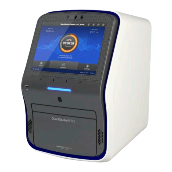
- Page 1 ™ QuantStudio 6 Pro and 7 Pro Real-Time PCR Systems USER GUIDE Publication Number MAN0018045 Revision E.0 For Research Use Only. Not for use in diagnostic procedures.
- Page 2 Life Technologies Holdings Pte Ltd | Block 33 | Marsiling Industrial Estate Road 3 | #07-06, Singapore 739256 For descriptions of symbols on product labels or product documents, go to thermofisher.com/symbols-definition. The information in this guide is subject to change without notice. DISCLAIMER: TO THE EXTENT ALLOWED BY LAW, THERMO FISHER SCIENTIFIC INC.
- Page 3 Revision Date Description 22 August 2019 v1.1.0 • Corrected the text on the buttons for the following items: – Add facial authentication to an existing instrument profile. – View the license agreement. – Reset the instrument (restore factory default). • Added the following items: –...
-
Page 4: Table Of Contents
Contents ■ CHAPTER 1 Product information ..........13 Network and password security requirements . - Page 5 Contents System template file names ........... . . 33 System template file names for the 96-well 0.2-mL block .
- Page 6 Contents Set up or remove the Auto Delta feature ........58 Configure ramp rates .
- Page 7 Contents ■ CHAPTER 7 Calibrate and verify instrument performance ..... 79 Instrument and block calibration ..........79 Calibration and verification schedule .
- Page 8 Contents If you link when you are signed in to the instrument ....... 115 If you link when you are not signed in to the instrument .
- Page 9 Contents View audit records ............140 Use the instrument when the SAE server is offline .
- Page 10 Contents Configure maintenance and service settings ........159 Request technical support with Smart Help .
- Page 11 Contents Download and install the desktop software ........179 Computer requirements for the desktop software .
- Page 12 Contents ■ APPENDIX E Documentation and support ........206 Related documentation .
-
Page 13: Chapter 1 Product Information
Product information ■ Network and password security requirements ......13 ■ Instrument hardware description ........14 ■... -
Page 14: Instrument Hardware Description
Chapter 1 Product information Instrument hardware description Instrument hardware description Overview of the instrument ™ ™ The Applied Biosystems QuantStudio 6 Pro and 7 Pro Real-Time PCR Systems use fluorescent-based polymerase chain reaction (PCR) reagents to perform the following functions: •... -
Page 15: Features Of Each Instrument
Chapter 1 Product information Instrument hardware description • Smart Help to request technical support or instrument service directly from the instrument • Barcode scanner for tracking plates Features of each instrument Feature ™ ™ QuantStudio 6 Pro System QuantStudio 7 Pro System Decoupled six-by-six color filter Filter set Coupled five-color filter set... - Page 16 Chapter 1 Product information Instrument hardware description (continued) Filter wavelength (nm) Peak Example Color System dyes filter custom dyes Excitation Emission MUSTANG ™ ™ x5-m5 640 ± 10 682 ± 14 PURPLE dye, ® Deep- ® x6-m6 662 ± 10 711 ±...
-
Page 17: Overview Of Data Collection
Chapter 1 Product information Instrument hardware description Overview of data collection The instrument collects raw fluorescence data at different points during the PCR cycle, depending on the type of run performed. When you create a plate file, you can customize the optical filter channels through which the instrument collects data. -
Page 18: Autodelta Settings
Chapter 1 Product information Instrument hardware description ™ Figure 1 Three VeriFlex Zones Figure 2 Six VeriFlex ™ Zones ™ Note: Plate files are not compatible between the QuantStudio 6 Pro System and ™ the QuantStudio 7 Pro System. For more information, see “Compatibility of plate files”... -
Page 19: Parts Of The Instrument
Chapter 1 Product information Instrument hardware description Parts of the instrument Figure 3 Front of the instrument Cameras Proximity sensor Touchscreen Access door for block change Microphones Speakers USB port Drawer Indicator light QuantStudio ™ 6 Pro and 7 Pro Real-Time PCR Systems User Guide... - Page 20 Chapter 1 Product information Instrument hardware description Figure 4 Back of the instrument USB ports RS-232 port (service use only) Wi-Fi dongle port ON/OFF switch Ethernet port Power inlet receptacle Note: The instrument recognizes only one external storage device at a time for data transfer.
-
Page 21: Instrument Status Indicator
Chapter 1 Product information Hands-free features Instrument status indicator Indicator Instrument status Powered off Sleep mode Blue light changing brightness slowly Powering on Blue light changing brightness Standby Blue light moving inwards towards middle Drawer opening of instrument Blue light moving outwards towards side of Drawer closing instrument Blue light moving back and forth... -
Page 22: Indicators For The Hands-Free Features
Chapter 1 Product information Hands-free features Indicators for the hands-free features Indicators for facial authentication Display Status of facial authentication The Sign In screen displays Facial authentication for the instrument is enabled. • Facial authentication for the instrument is disabled. The Sign In screen does not display •... -
Page 23: Software Description
Chapter 1 Product information Software description For more information about linking a local instrument profile to a Connect profile, see “Link the instrument to your Connect account” on page 111 and “If you link when you are signed in to the instrument” on page 115. Software description Parts of the home screen Figure 5 Home screen... - Page 24 Chapter 1 Product information Software description Table 1 Parts of the home screen Element of the home Function screen Instrument name Set by the administrator to identify the instrument. Calendar Schedule time for a run or see runs that are scheduled. Microphone Shows the status of the microphone (see “Indicators for voice commands”...
-
Page 25: Connect And Cloud Definitions
Chapter 1 Product information Software description Table 1 Parts of the home screen (continued) Element of the home Function screen • Edit the file name convention. Instrument settings • View the run history, and transfer or delete data files. • Install, change, or remove the block and the heated cover. •... -
Page 26: Overview Of File Locations And Files
Chapter 1 Product information Software description (continued) Feature Instrument Desktop Connect Send plate files to the instrument run — — queue Access the plate file associated with — — last run on the instrument Load plate in instrument — — Start run —... - Page 27 Chapter 1 Product information Software description (continued) File location Description and function • Plate files can be retrieved from a network drive. Network drive • Data files can be saved to a network drive. • The instrument must be connected to a network or a computer. •...
- Page 28 Chapter 1 Product information Software description (continued) Item Description and function Supported in • A file that has been saved from a system template. Plate File Instrument Desktop • Can be edited and saved. From (Load plate file) Connect • Can be edited and saved as a separate plate file. •...
-
Page 29: Components Of The Files
Chapter 1 Product information Software description Components of the files Component Instrument Desktop Connect • Data file name • Experiment file name Properties • Reagent information • Plate barcode – Name • User name – Type • Instrument type – Lot number •... -
Page 30: Third-Party Software
Chapter 1 Product information Types of runs Third-party software Before installing third-party software on the computer running the desktop software, confirm that the third-party software will not do the following: • Restrict Ethernet communication. • Interfere with instrument or computer operation. Network connection options You can connect an instrument to a network or computer in the configurations listed below. -
Page 31: Relative Standard Curve Run
Chapter 1 Product information Types of runs Relative standard curve run A relative standard curve runs determines the relative target quantity in samples. 1. The software measures amplification of the target of interest and of an endogenous control target in a standard dilution series, in a reference (calibrator) sample, and in test samples. -
Page 32: Genotyping Run
Chapter 1 Product information Types of runs Genotyping run A genotyping runs detects the single nucleotide polymorphism (SNP) variants of a target nucleic acid sequence. ™ Genotyping experiments use preformulated TaqMan SNP Genotyping Assays that include the following components: • Two sequence-specific primers for amplification of sequences containing the SNP of interest •... -
Page 33: System Template File Names
Chapter 1 Product information System template file names System template file names ™ The first part of the file name varies, based on the instrument (QuantStudio 6 Pro ™ System or QuantStudio 7 Pro System). The instrument will display the system templates applicable to the block that is installed. -
Page 34: System Template File Names For The 96-Well 0.1-Ml Block
Chapter 1 Product information System template file names (continued) System template name Run type • Comparative C QS7Pro-96-Well-0-2ml_RQ_Fast.edt • 96-well, 0.2-mL Standard plate • Fast cycling mode • Comparative C QS7Pro-96-Well-0-2ml_RQ_Std.edt • 96-well, 0.2-mL Standard plate • Standard cycling mode •... - Page 35 Chapter 1 Product information System template file names (continued) System template name Run type • Melt curve run (no PCR stage) QS7Pro-96-Well-0-1ml_Melt_Std.edt • 96-well, 0.1-mL Standard plate • Standard cycling mode • Presence/absence run QS7Pro-96-Well-0-1ml_PA_Fast.edt • 96-well, 0.1-mL Standard plate •...
-
Page 36: System Template File Names For The 384-Well Block
Chapter 1 Product information System template file names System template file names for the 384-well block System template name Run type • Genotyping run QS7Pro-384-Well-GT-Fast.edt • 384-well plate • Fast cycling mode • Genotyping run QS7Pro-384-Well-GT-Std.edt • 384-well plate • Standard cycling mode •... - Page 37 Chapter 1 Product information System template file names (continued) System template name Run type • Relative standard curve run QS7Pro-384-Well-RSC-Fast.edt • 384-well plate • Fast cycling mode • Relative standard curve run QS7Pro-384-Well-RSC-Std.edt • 384-well plate • Standard cycling mode •...
-
Page 38: Workflow
Chapter 1 Product information Workflow Workflow Sign in to your instrument profile or your Connect account (PIN or facial authentication) ▼ Open a plate file (System template or saved plate file) ▼ (Optional) Edit the plate file ▼ Load the plate into the instrument ▼... -
Page 39: Chapter 2 Get Started
Get started ■ Precautions for use ........... 39 ■... -
Page 40: Installation And Instrument Verification
Chapter 2 Get started Installation and instrument verification Installation and instrument verification The instrument is installed by a representative from Thermo Fisher Scientific. The following tasks will be performed during the installation process: • Unpack the instrument and the computer •... -
Page 41: Use The Instrument As A Guest
Chapter 2 Get started Overview of guest access Use the instrument as a guest If the Guest button is not visible on the Sign In screen, guest access has been disabled. An administrator must enable guest access (see “Require sign-in” on page 107). -
Page 42: Power On The Instrument
Chapter 2 Get started Power on the instrument Power on the instrument If left unattended, the instrument automatically enters sleep mode to conserve power. The default time that an instrument is inactive before going into sleep mode is 15 minutes. 1. -
Page 43: Sign In
Chapter 2 Get started Sign in Sign in Sign in with a PIN Create an instrument profile before signing into the instrument (see “Create a new local instrument profile” on page 112 and “Link the instrument to your Connect account” on page 111). 1. -
Page 44: Enable Or Disable The Microphone
Chapter 2 Get started Enable or disable the microphone The user is signed into the instrument and the home screen is displayed. Enable or disable the microphone The microphone can be disabled if the voice command function is available. A blue microphone icon indicates that the voice command function is available. -
Page 45: Sign Out
Chapter 2 Get started Sign out (continued) Instrument audio Voice command Instrument action output If yes, the instrument stops the run "Are you sure you want and displays the Plate properties End run to stop the run? Yes or screen. no."... -
Page 46: Chapter 3 Create And Run Plates On The Instrument
Create and run plates on the instrument ■ Options to run a plate ..........46 ■... - Page 47 Chapter 3 Create and run plates on the instrument Options to run a plate 3. Tap the template file name in the right column. The Plate Properties screen is displayed. 4. (Optional) In the Plate Properties screen, edit the Data file name. The default file name is the template name appended with the date and time.
-
Page 48: Repeat The Last Run
Chapter 3 Create and run plates on the instrument Options to run a plate Figure 7 Home screen during a run For options during a run, see Chapter 5, “Options for a run”. Repeat the last run The last run is associated with the profile. It is not the last run for the instrument. 1. -
Page 49: Overview Of Customized Data Export
Chapter 3 Create and run plates on the instrument Overview of customized data export If the connection between the instrument and the location that was selected to save the data file is interrupted, the instrument completes the run. The data file is saved on the instrument. -
Page 50: (Optional) Scan A Barcode Using A Barcode Scanner
Chapter 3 Create and run plates on the instrument (Optional) Scan a barcode using a barcode scanner (Optional) Scan a barcode using a barcode scanner The instrument is compatible with an optional Handheld Barcode Scanner (Cat. No. 4488442, purchased separately). The barcode scanner reads Code 128 (alphanumeric), which supports 128 ASCII character barcodes. -
Page 51: Unload A Plate From The Instrument
Chapter 3 Create and run plates on the instrument Unload a plate from the instrument Unload a plate from the instrument CAUTION! PHYSICAL INJURY HAZARD. During instrument operation, the plate temperature can reach 100°C. Allow it to cool to room temperature before handling. The status dial displays Run complete when the run is finished. -
Page 52: Chapter 4 Edit A Plate Before Starting A Run
Edit a plate before starting a run ■ Overview of a template file with restricted editing ......52 ■... -
Page 53: Options To Edit The Properties Of A Plate File
Chapter 4 Edit a plate before starting a run Options to edit the properties of a plate file Options to edit the properties of a plate file The following files can be edited: • A system template (see “Create and run a plate from a system template or a saved plate file”... -
Page 54: Options To Edit The Method Of A Plate File
Chapter 4 Edit a plate before starting a run Options to edit the method of a plate file Options to edit the method of a plate file The following files can be edited: • A system template (see “Create and run a plate from a system template or a saved plate file”... -
Page 55: Method Elements
Chapter 4 Edit a plate before starting a run Options to edit the method of a plate file Method elements Method tab Number of cycles for the stage Heated cover temperature Temperature for the step Reaction volume Hold time for the step Stage of thermal protocol Data collection point Step within a stage... -
Page 56: Add Or Remove Steps
Chapter 4 Edit a plate before starting a run Options to edit the method of a plate file Add or remove steps Add a PCR step or remove a PCR step. 1. In the Method tab, tap Edit4Advanced4Manage steps. Note: Use to navigate through the method if it is not all displayed. -
Page 57: Set Up Or Remove Veriflex ™ Zones
Chapter 4 Edit a plate before starting a run Options to edit the method of a plate file 2. Tap (Data collection location) to designate a step as a data collection location or to remove data collection from the step. (Data collection location) button functions as an on-off switch. -
Page 58: Set Up Or Remove The Auto Delta Feature
Chapter 4 Edit a plate before starting a run Options to edit the method of a plate file 2. Tap the temperature field in the appropriate VeriFlex ™ Zone. 3. Enter a temperature, then tap Enter. The temperatures in adjacent zones must have a difference of ≤5°C. 4. -
Page 59: Configure Ramp Rates
Chapter 4 Edit a plate before starting a run Options to edit the method of a plate file 8. In the Method tab, tap 4Remove4Done to remove the Auto Delta setting. Note: The Auto Delta setting is removed from the Method tab. Indicates that this is the Method tab where Auto Delta settings can be removed. -
Page 60: Options To Edit The Well Details Of A Plate File
Chapter 4 Edit a plate before starting a run Options to edit the well details of a plate file Options to edit the well details of a plate file The following files can be edited: • A system template (see page 46) A system template that is edited must be saved as a plate file. -
Page 61: View A 384-Well Plate
Chapter 4 Edit a plate before starting a run Options to edit the well details of a plate file Select all button Plate view button Well table view button Color by dropdown list View a 384-well plate The Plate tab displays a 384-well plate if the 384-well block is installed. The plate can be edited in the 384-well view. -
Page 62: Assign Or Edit A Well
Chapter 4 Edit a plate before starting a run Options to edit the well details of a plate file 1. In the region of the 384-well plate that you want to zoom in on, pinch outwards with two fingers. 2. (Optional) To change the region that you are zoomed in on, use two fingers to drag the plate in the appropriate direction. -
Page 63: Add Or Edit The Reagent Details
Chapter 4 Edit a plate before starting a run Options to edit the well details of a plate file Add or edit the reagent details 1. In the Plate tab, tap one of the following items. • A single well •... -
Page 64: Edit A Passive Reference Dye
Chapter 4 Edit a plate before starting a run Options to edit the well details of a plate file 3. (Optional) Tap Clear all. 4. Tap a row in the table, then delete the information in each field. • Reagent name •... -
Page 65: Chapter 5 Options For A Run
Options for a run ■ Screens available during a run ......... 65 ■... -
Page 66: Edit A Plate File During A Run
Chapter 5 Options for a run Edit a plate file during a run Figure 9 Home screen during a run Arrow Actions menu Edit a plate file during a run The targets and samples can be added or edited after a run has started. The method cannot be edited after a run has started. -
Page 67: Pause An Instrument Run
Chapter 5 Options for a run Pause an instrument run Pause an instrument run Pause a run to add reagents to the plate or to edit the number of cycles. 1. In the home screen during a run, tap (Actions). See Figure 9 on page 66. -
Page 68: View The Method During A Run
Chapter 5 Options for a run View the method during a run View the method during a run 1. In the home screen during a run, swipe left once or tap the right arrow ( ) once. Start time Method, including the current stage End time Time remaining 2. -
Page 69: Adjust The Display Of Real-Time Plots During A Run
Chapter 5 Options for a run View the time remaining during a run 2. (Optional) Tap the dropdown list then select the view for the plot. • Linear • Log 10 3. (Optional) Tap Actions4Analyze amp plots. 4. (Optional) Tap Actions4View well details to see the amplification for a specific well. -
Page 70: Unlock The Touchscreen During A Run
Chapter 5 Options for a run Unlock the touchscreen during a run Unlock the touchscreen during a run The touchscreen can be unlocked by the user who locked it or an administrator. The touchscreen automatically unlocks when the run is complete. 1. -
Page 71: Cancel A Scheduled Run
Chapter 5 Options for a run Instrument Schedule Cancel a scheduled run 1. In the home screen, tap (Calendar). 2. Select a view. • Day • Week • Month 3. Tap the reservation. The Edit Reservation screen is displayed. 4. Tap Cancel Reservation, then tap Yes. QuantStudio ™... -
Page 72: Chapter 6 View And Manage Files
View and manage files ■ Manage plate files ........... . 72 ■... -
Page 73: Delete Plate Files
Chapter 6 View and manage files Manage data files Delete plate files System templates cannot be deleted. A plate file that was saved from a system template can be deleted. For descriptions of files, see “Files” on page 27. 1. In the home screen, tap Load plate file or Set up run. - Page 74 Chapter 6 View and manage files Manage data files Figure 10 QC Check passed QC Check Figure 11 Review required for QC Check QC Check 2. See the QC data in the QuantStudio ™ Design and Analysis Software v2 or the ™...
-
Page 75: View An Amplification Plot After A Run
Chapter 6 View and manage files Manage data files View an amplification plot after a run The status dial displays Run complete when a run is complete. The amplification plot can only be viewed immediately after a run. After Done is tapped, the amplification plot can no longer be viewed on the instrument. -
Page 76: Transfer A Data File Immediately After A Run
Chapter 6 View and manage files Manage data files Transfer a data file immediately after a run This section describes the transfer of a data file immediately after a run. To transfer a data file or a set of data files at a later time, see “Transfer data files at a later time” on page 76. -
Page 77: View The List Of Data Files On The Instrument
Chapter 6 View and manage files Manage data files 1. Tap (Settings)4Run history. The Run History screen is displayed. It contains a list of the runs performed on the instrument associated with the profile. Administrators can view all of the runs performed. - Page 78 Chapter 6 View and manage files Manage data files 1. In the home screen, tap (Settings)4Run history. The Run History screen is displayed. It contains a list of the runs performed on the instrument associated with the profile. Administrators can view all of the runs performed.
-
Page 79: Chapter 7 Calibrate And Verify Instrument Performance
Calibrate and verify instrument performance ■ Instrument and block calibration ........79 ■... -
Page 80: Calibration And Verification Schedule
Chapter 7 Calibrate and verify instrument performance Calibration and verification schedule Calibration and verification schedule The instrument and block will be calibrated during the installation. To ensure optimal performance, perform calibrations at the recommended frequency. Note: After instrument calibration, we recommend performing instrument verification using the provided RNase P plate. -
Page 81: Calibration Descriptions
Chapter 7 Calibrate and verify instrument performance Calibration descriptions Note: To prepare custom dye plates and to perform custom calibrations, see “Calibrate custom dyes” on page 98. Calibration descriptions The combination of the instrument and the block is calibrated (see “Instrument and block calibration”... -
Page 82: Set Calibration Frequency And Reminders On The Instrument
Chapter 7 Calibrate and verify instrument performance View the calibration status and set reminders 1. In the home screen, tap (Settings)4Maintenance and service4Calibration4Status and reminders. The Status and Reminders screen is displayed. It shows the following information: • Type of calibration •... -
Page 83: Export A Calibration Report
Chapter 7 Calibrate and verify instrument performance Export a calibration report 4. In the Summary tab: • Tap Calibrations to view the status of each calibration type. • (Optional) Tap Calibration Reminders to set the calibration reminder time table and enter the notification email address or addresses. Note: More than one email address can receive the calibration reminders. -
Page 84: Perform Roi/Uniformity, Background, And Dye Calibrations
Chapter 7 Calibrate and verify instrument performance Perform ROI/uniformity, background, and dye calibrations Perform ROI/uniformity, background, and dye calibrations Calibration workflow Perform an ROI/uniformity calibration You are automatically prompted to perform background calibration. ▼ Perform a background calibration Perform any time that ROI/uniformity calibrations are current. ▼... - Page 85 Chapter 7 Calibrate and verify instrument performance Perform ROI/uniformity, background, and dye calibrations Thaw, vortex, and centrifuge a calibration plate IMPORTANT! Keep calibration plates protected from light until you perform the calibration. Do not remove the plate from its packaging until you are ready to use it. Prolonged exposure to light can diminish the fluorescence of the dyes in the wells of calibration plates.
-
Page 86: Perform Calibrations
Chapter 7 Calibrate and verify instrument performance Perform ROI/uniformity, background, and dye calibrations Perform calibrations 1. In the home screen tap (Settings)4Maintenance and service4Calibration. The Calibration screen is displayed. 2. In the Calibration screen, select a calibration type. Calibration type ROI/uniformity ROI and uniformity Background... -
Page 87: View The Calibration Images
Chapter 7 Calibrate and verify instrument performance Perform ROI/uniformity, background, and dye calibrations 8. (For calibrations that fail) Select an option. Option Description Details View the calibration images. Transfer EDS Transfer the calibration file to Connect, a USB drive, or a network drive (recommended for troubleshooting). - Page 88 Chapter 7 Calibrate and verify instrument performance Perform ROI/uniformity, background, and dye calibrations • Calibration name • The operator • Result • Reagent name, part number, lot number, and expiration date • Date • Comments. • Whether this calibration is current 4.
-
Page 89: Transfer Calibration Results
Chapter 7 Calibrate and verify instrument performance Perform ROI/uniformity, background, and dye calibrations Transfer calibration results 1. In the home screen, tap (Settings)4Maintenance and service4Calibration4Status and reminders. The Status and Reminders screen is displayed. 2. Tap a calibration type in the table. 3. -
Page 90: Identify Contamination
Chapter 7 Calibrate and verify instrument performance Perform ROI/uniformity, background, and dye calibrations Observation Possible cause Recommended action Calibration failed but plate is The incorrect plate was used for Use the plate that matches the calibration undamaged calibration performed. performed. The plate was improperly Repeat the calibration with the plate properly prepared. -
Page 91: Perform Verification Using Rnase P Plates
Chapter 7 Calibrate and verify instrument performance Perform verification using RNase P plates • Safety glasses • Deionized water IMPORTANT! Wear powder-free gloves while creating the background plate. 1. Remove a reaction plate from its box and place it on a clean, dry surface. 2. -
Page 92: Rnase P Instrument Verification Plate
Chapter 7 Calibrate and verify instrument performance Perform verification using RNase P plates RNase P instrument verification plate The RNase P plate contains the reagents necessary for the detection and quantitation of genomic copies of the human RNase P gene (a single-copy gene encoding the RNase moiety of the RNase P enzyme). -
Page 93: Performance Specifications Pass Criteria
Chapter 7 Calibrate and verify instrument performance Perform verification using RNase P plates Figure 13 384-well RNase P plate NTC (no template control) STD 10,000 copies STD 1,250 copies STD 10,000 copies STD 2,500 copies Unknown A (5,000) STD 5,000 copies Unknown B (10,000) Performance specifications pass criteria After the run, the software calculates average copy number values and standard... -
Page 94: Perform Rnase P Verification
Chapter 7 Calibrate and verify instrument performance Perform verification using RNase P plates Thaw, vortex, and centrifuge an RNase P plate IMPORTANT! Expose the RNase P plate to room temperature for no more than 45 minutes, inclusive of thawing and preparation time. After thawing, the RNase P plate cannot be refrozen. - Page 95 Chapter 7 Calibrate and verify instrument performance Perform verification using RNase P plates 5. When the run is complete and the screen displays Complete, tap View results to confirm the status of the run. Verification status Action Passed Instrument is ready for use. Failed See “Troubleshoot verification failure”...
-
Page 96: Troubleshoot Verification Failure
Chapter 7 Calibrate and verify instrument performance Perform verification using RNase P plates Troubleshoot verification failure Observation Possible cause Recommended action Verification failed The plate was improperly Ensure the following: prepared. • The correct plate was used for the verification performed. •... - Page 97 Chapter 7 Calibrate and verify instrument performance Perform verification using RNase P plates Observation Possible cause Recommended action Verification failed but plate is The plate was improperly Repeat the verification with a new properly undamaged prepared. prepared plate. (continued) Note: Each RNase P plate can only be used once.
-
Page 98: Calibrate Custom Dyes
Chapter 7 Calibrate and verify instrument performance Calibrate custom dyes Calibrate custom dyes Overview of custom dyes The instrument can run assays designed with custom dyes. The following items are defined as custom dyes: • Dyes that are not manufactured by Thermo Fisher Scientific. •... - Page 99 Chapter 7 Calibrate and verify instrument performance Calibrate custom dyes • Dilute the dye in buffer compatible with your Master Mix. • (Intercalating dyes only) Add the appropriate amount of amplified PCR product to generate fluorescence. Prepare a custom dye dilution plate IMPORTANT! Wear powder-free gloves throughout the procedure.
- Page 100 Chapter 7 Calibrate and verify instrument performance Calibrate custom dyes IMPORTANT! Keep the bottom of the plate clean. Fluids and other contaminants on the bottom of the plate can contaminate the sample block and cause an abnormally high background signal. Run the dilution plate IMPORTANT! Do not run the dilution plate as a calibration.
-
Page 101: Calibrate The Custom Dye
Chapter 7 Calibrate and verify instrument performance Calibrate custom dyes 2. For each replicate population of dilutions, select the wells in the plate layout to view in the plot. 3. Examine the raw data to identify the wells yielding signals according to the ranges shown in the following table. - Page 102 Chapter 7 Calibrate and verify instrument performance Calibrate custom dyes IMPORTANT! Keep the bottom of the plate clean. Fluids and other contaminants on the bottom of the plate can contaminate the sample block and cause an abnormally high background signal. Add a custom dye to the instrument 1.
- Page 103 Chapter 7 Calibrate and verify instrument performance Calibrate custom dyes 6. Load the plate into the instrument, then tap Start. CAUTION! The instrument should be used by trained operators who have been warned of the moving parts hazard. Calibration complete is displayed when the run is complete. 7.
-
Page 104: Calibrate For A Custom Melt Curve Run
Chapter 7 Calibrate and verify instrument performance Calibrate for a custom melt curve run 9. Select an action depending on whether the custom dye calibration passed or failed. Calibration Action status Passed 1. Tap Accept Results or Reject Results. Note: Accepting the results saves the calibration data to the instrument and overwrites existing data. - Page 105 Chapter 7 Calibrate and verify instrument performance Calibrate for a custom melt curve run 3. Select or add a dye, then select a filter set appropriate for your dye's wavelength (see filter-wavelength table below). Note: See your reagent kit documentation for dye name and wavelength information.
- Page 106 Chapter 7 Calibrate and verify instrument performance Calibrate for a custom melt curve run 9. Select an action depending on whether the custom dye calibration passed or failed. Calibration Action status Passed 1. Tap Accept Results or Reject Results. Note: Accepting the results saves the calibration data to the instrument and overwrites existing data.
-
Page 107: Chapter 8 Manage Profiles
Manage profiles ■ Require sign-in ........... . . 107 ■... -
Page 108: Recommended Order To Set Up Profiles
Chapter 8 Manage profiles Recommended order to set up profiles Recommended order to set up profiles Task Description The first profile on the instrument becomes the instrument administrator. Create a profile for the instrument The first profile is set up during the initial install with a representative administrator. -
Page 109: Connect Instrument Profile Roles And Functions
Chapter 8 Manage profiles Connect instrument profile roles and functions – Smart Help is not available. – Separate profiles are required for each instrument if multiple instruments are used. • Connect profile – Plate files and data files are stored on the instrument. –... - Page 110 Chapter 8 Manage profiles Test the connection to the Connect platform 2. Tap Test connection. If the connection can be established, You are able to connect to the Connect platform will be displayed. If the connection cannot be established, Unable to connect will be displayed. QuantStudio ™...
-
Page 111: Link The Instrument To Your Connect Account
Chapter 8 Manage profiles Link the instrument to your Connect account 3. Tap Close. Link the instrument to your Connect account This section describes using your Connect account when you use the instrument for the first time. The first time you use your Connect account on an instrument, you will be prompted to create a four-digit numerical PIN. -
Page 112: Create A New Local Instrument Profile
Chapter 8 Manage profiles Create a new local instrument profile 3. Tap a connection option. Option Action Mobile Note: Before selecting this option, install and sign in to the devices Connect application on your mobile device. On the instrument: 1. Tap Mobile devices. -
Page 113: Link A Local Profile To A Connect Profile
Chapter 8 Manage profiles Link a local profile to a Connect profile 4. Tap the PIN (4 digits required) field, enter a four-digit numerical PIN, then tap Enter. Tap the Show PIN checkbox to show or hide the PIN. 5. Tap the Confirm PIN field, enter the four-digit numerical PIN again, then tap Enter. -
Page 114: Unlink A Connect Account
Chapter 8 Manage profiles Unlink a Connect account 4. Tap a connection option. Option Action Mobile Note: Before selecting this option, install and sign in to the devices Connect application on your mobile device. On the instrument: 1. Tap Mobile devices. 2. -
Page 115: If You Link When You Are Signed In To The Instrument
Chapter 8 Manage profiles If you link when you are signed in to the instrument If you link when you are signed in to the instrument In this scenario, your local instrument profile name is created manually on the instrument before you link. Your local instrument profile name differs from your Connect instrument profile name. -
Page 116: If You Link When You Are Not Signed In To The Instrument
Chapter 8 Manage profiles If you link when you are not signed in to the instrument If you link when you are not signed in to the instrument In this scenario, your local instrument profile name is created automatically at the time that you link. -
Page 117: Manage Individual Instrument Profiles
Chapter 8 Manage profiles Manage individual instrument profiles Manage individual instrument profiles Create an administrator instrument profile during initial start-up The first instrument profile that is created during installation is assigned the role of an instrument administrator. Administrators can grant administrative privileges to other users (see “Enable or disable administrator privileges”... -
Page 118: Add Facial Authentication To An Existing Instrument Profile
Chapter 8 Manage profiles Manage individual instrument profiles Add facial authentication to an existing instrument profile When a profile is set up for facial authentication, the photographs should reflect how the user appears in the lab. For example, safety glasses should be worn to set up facial authentication if safety glasses will be worn when signing in. -
Page 119: Change The Pin For A Connect Profile
Chapter 8 Manage profiles Manage all instrument profiles as an administrator Change the PIN for a Connect profile This section describes changing a PIN for a Connect profile. To change a PIN for a local instrument profile, see “Change the PIN for an instrument profile” on page 118. 1. -
Page 120: Add A Profile
Chapter 8 Manage profiles Manage all instrument profiles as an administrator The profile must have a new PIN added the next time it is accessed. Add a profile 1. In the home screen, tap (Profile). The My Profile screen is displayed. 2. -
Page 121: Delete A Profile
Chapter 8 Manage profiles Manage all instrument profiles as an administrator Delete a profile 1. In the home screen, tap (Profile). The My Profile screen is displayed. 2. Tap All accounts. 3. Tap a profile. The Manage Account screen is displayed. 4. - Page 122 Use the instrument with the Security, Auditing, and E‑signature (SAE) v2.0 module ■ Overview of the Security, Auditing, and E‑signature (SAE) v2.0 module components ..........123 ■...
-
Page 123: Chapter 9 Use The Instrument With The Security, Auditing, And E-Signature (Sae) V2.0 Module
Chapter 9 Use the instrument with the Security, Auditing, and E‑signature (SAE) v2.0 module ‑ signature (SAE) v2.0 module components Overview of the Security, Auditing, and E Overview of the Security, Auditing, and E‑signature (SAE) v2.0 module components The Security, Auditing, and E‑signature (SAE) v2.0 module includes three components: •... -
Page 124: Security, Auditing, And E-Signature (Sae) V2.0 Module Functions
Chapter 9 Use the instrument with the Security, Auditing, and E‑signature (SAE) v2.0 module ‑ signature (SAE) v2.0 module functions Security, Auditing, and E Security, Auditing, and E‑signature (SAE) v2.0 module functions Functions that are controlled The following functions are controlled, depending on the user role: •... -
Page 125: Functions That Can Be Audited
Chapter 9 Use the instrument with the Security, Auditing, and E‑signature (SAE) v2.0 module ‑ signature (SAE) v2.0 module roles Security, Auditing, and E Functions that can be audited Certain instrument functions can be audited. This depends on how the SAE administrator has configured the audit settings. -
Page 126: Dialog Boxes In The Sae Module
Chapter 9 Use the instrument with the Security, Auditing, and E‑signature (SAE) v2.0 module Dialog boxes in the SAE module Dialog boxes in the SAE module Some of the features and functions described might not be accessible to you. The features and functions that are available depend on the way that the SAE administrator has configured them. -
Page 127: Profiles When The Sae Module Is Enabled
Chapter 9 Use the instrument with the Security, Auditing, and E‑signature (SAE) v2.0 module Profiles when the SAE module is enabled Profiles when the SAE module is enabled After the SAE module is enabled on the instrument, the local instrument profiles and the Connect cloud-based platform profiles will not be available. -
Page 128: Compatibility Between Sae-Enabled And Sae-Disabled Components
Chapter 9 Use the instrument with the Security, Auditing, and E‑signature (SAE) v2.0 module SAE-enabled system components • QuantStudio ™ 7 Pro Real-Time PCR System plate file—SAE-enabled plate files ™ are created in the QuantStudio Design and Analysis Software v2 with SAE enabled. -
Page 129: Enable Sae Functions
Chapter 9 Use the instrument with the Security, Auditing, and E‑signature (SAE) v2.0 module Enable SAE functions (continued) Functionality with an SAE-enabled plate or Functionality with an SAE-disabled plate or Component data file data file • The plate file can be opened and edited. ™... -
Page 130: Enable Sae On The Instrument And Specify The Sae Server (Administrator Only)
Chapter 9 Use the instrument with the Security, Auditing, and E‑signature (SAE) v2.0 module Enable SAE functions Enable SAE on the instrument and specify the SAE server (administrator only) This procedure requires a local administrator profile on the instrument and an SAE administrator account in the SAE Administrator Console. -
Page 131: Connect To The Sae Server
Chapter 9 Use the instrument with the Security, Auditing, and E‑signature (SAE) v2.0 module Enable SAE functions Connect to the SAE server • Install the SAE Administrator Console and the SAE server on a computer with a static IP address. •... -
Page 132: Disable Sae On The Instrument (Administrator Only)
Chapter 9 Use the instrument with the Security, Auditing, and E‑signature (SAE) v2.0 module Disable SAE on the instrument (administrator only) Disable SAE on the instrument (administrator only) This procedure requires a local administrator profile and an SAE administrator account. Sign in with a local administrator account (see “Sign in as a local administrator with SAE enabled”... -
Page 133: Sign In As A Local Administrator With Sae Enabled
Chapter 9 Use the instrument with the Security, Auditing, and E‑signature (SAE) v2.0 module Sign in as a local administrator with SAE enabled Sign in as a local administrator with SAE enabled Sign in as a local administrator to access the instrument settings. Plate files are not accessible if you are signed in as a local administrator. -
Page 134: Sign In With Sae Enabled
Chapter 9 Use the instrument with the Security, Auditing, and E‑signature (SAE) v2.0 module Sign in with SAE enabled Sign in with SAE enabled You must create a profile on the SAE Administrator Console before you sign in when SAE is enabled on the instrument. 1. -
Page 135: Sign Out With Sae Enabled
Chapter 9 Use the instrument with the Security, Auditing, and E‑signature (SAE) v2.0 module Sign out with SAE enabled Figure 17 Home screen Sign out with SAE enabled 1. In the home screen, tap (Profile). The My Profile screen is displayed. The SAE button is selected and the profile that is signed in is listed. -
Page 136: Change Your Sae Account Password On The Instrument
Chapter 9 Use the instrument with the Security, Auditing, and E‑signature (SAE) v2.0 module Change your SAE account password on the instrument Change your SAE account password on the instrument You must be signed in with the instrument in SAE mode (see “Sign in with SAE enabled”... -
Page 137: Sign A Plate Setup
Chapter 9 Use the instrument with the Security, Auditing, and E‑signature (SAE) v2.0 module Sign a plate setup Figure 20 Edit My Profile screen 3. Tap the Old password field, enter the current SAE account password, then tap Enter. 4. Tap the New password field, enter a new SAE account password, then tap Enter. -
Page 138: Enter An Audit Reason
Chapter 9 Use the instrument with the Security, Auditing, and E‑signature (SAE) v2.0 module Enter an audit reason 3. Tap the template file name in the right column. The Plate Properties screen is displayed. 4. In the Plate Properties screen, tap Actions. The Actions screen is displayed. -
Page 139: View Signing Records For A Plate File
Chapter 9 Use the instrument with the Security, Auditing, and E‑signature (SAE) v2.0 module View signing records for a plate file View signing records for a plate file 1. In the home screen, tap one of the following options: • (Load plate file) •... -
Page 140: View Audit Records
Chapter 9 Use the instrument with the Security, Auditing, and E‑signature (SAE) v2.0 module View audit records 6. Tap a row to view the details. 7. Tap Close to return to the Signing records screen. View audit records The audit records cannot be viewed on the instrument touchscreen. The audit ™... -
Page 141: Use The Instrument When The Sae Server Is Offline
Chapter 9 Use the instrument with the Security, Auditing, and E‑signature (SAE) v2.0 module Use the instrument when the SAE server is offline Use the instrument when the SAE server is offline If your SAE administrator has configured your instrument to allow use when the SAE server is offline (Client offline login System setting in the SAE module), you can use the instrument for the period of time specified by the SAE administrator for Client offline login. -
Page 142: Signing In After Automatic Screen Locking
Chapter 9 Use the instrument with the Security, Auditing, and E‑signature (SAE) v2.0 module Signing in after automatic screen locking Signing in after automatic screen locking Depending on the way your SAE administrator has configured your instrument, the instrument touchscreen may automatically lock after a specified duration. An Administrator role or a Scientist role can sign in after automatic screen locking. -
Page 143: Chapter 10 Maintain The Instrument
Maintain the instrument ■ Install a block ............143 ■... -
Page 144: Change The Block
Chapter 10 Maintain the instrument Change the block Change the block CAUTION! PHYSICAL INJURY HAZARD. During instrument operation, the sample block temperature can reach 100°C. Allow it to cool to room temperature before handling. This section describes changing a block and heated cover when there is already a block installed. -
Page 145: Remove The Block
Chapter 10 Maintain the instrument Remove the block The instrument displays one of the following options, depending on the calibration status: • Confirmation that the block was installed successfully and the expiration date of the current calibration. • A warning that the block is not calibrated on the instrument. •... -
Page 146: Decontaminate The Sample Block
Chapter 10 Maintain the instrument Decontaminate the sample block It is recommended to store the block and the heated cover in the provided protective box when they are not installed on an instrument. Decontaminate the sample block Perform this procedure to eliminate fluorescent contaminants from the instrument sample block. -
Page 147: Clean The Sample Block
Chapter 10 Maintain the instrument Decontaminate the sample block Clean the sample block CAUTION! PHYSICAL INJURY HAZARD. During instrument operation, the sample block temperature can reach 100°C. Allow it to cool to room temperature before handling. IMPORTANT! Wear powder‑free gloves when you perform this procedure. IMPORTANT! Always use deionized water to rinse wells after cleaning with bleach or ethanol solution. -
Page 148: Detailed Procedures For Cleaning The Sample Block
Chapter 10 Maintain the instrument Decontaminate the sample block 8. If the contamination remains, clean the contaminated wells with a 10% bleach solution. Repeat step 2 to step 6 with a 10% bleach solution (see “Detailed procedures for cleaning the sample block” on page 148). IMPORTANT! Always use deionized water to rinse wells after cleaning with bleach or ethanol solution. -
Page 149: Replace The Instrument Fuses
Chapter 10 Maintain the instrument Replace the instrument fuses Replace the instrument fuses CAUTION! FIRE HAZARD. For continued protection against the risk of fire, replace fuses only with listed and certified fuses of the same type and rating as those currently in the instrument. -
Page 150: Power On Or Off, Store, And Move
Chapter 10 Maintain the instrument Power on or off, store, and move 6. Align each new fuse in the fuse holder as shown in the figure below. Fuse alignment in the fuse holder 7. Install the fuse holder back into the instrument. 8. -
Page 151: Power On The Instrument
Chapter 10 Maintain the instrument Power on or off, store, and move Power on the instrument If left unattended, the instrument automatically enters sleep mode to conserve power. The default time that an instrument is inactive before going into sleep mode is 15 minutes. -
Page 152: Prepare The Instrument To Store, Move, Or Ship
Chapter 10 Maintain the instrument Power on or off, store, and move Prepare the instrument to store, move, or ship Remove the block and heated cover to store, move, or ship the instrument. It is recommended to store the block and heated cover in the provided protective box when they are not installed on an instrument. -
Page 153: Chapter 11 Configure The Instrument Settings
Configure the instrument settings ■ View the instrument details ......... . . 153 ■... -
Page 154: View The License Agreement
Chapter 11 Configure the instrument settings View the license agreement • Instrument model name • Block type • Wired IP address • Software version • Wired MAC address • Firmware version • Wireless IP address • User interface version • Wireless MAC address •... -
Page 155: Configure The Instrument Settings
Chapter 11 Configure the instrument settings Configure the instrument settings 2. Tap Privacy. The privacy policy is displayed. 3. Tap Close. Configure the instrument settings Enable or disable demonstration mode Note: The instrument restarts when demonstration mode is turned on or off. When the instrument is in demonstration mode, the following features apply: •... -
Page 156: Configure The Heated Cover Settings
Chapter 11 Configure the instrument settings Configure the instrument settings Configure the heated cover settings The heated cover can be heated when the instrument is idle or it can be left without being heated when the instrument is idle. To save power, configure the settings so the heated cover is left without heating. -
Page 157: Select The Region For The Connect Platform
Chapter 11 Configure the instrument settings Configure the instrument settings 3. Enter the information that is needed for a wireless or wired connection. • Tap the Network field to enter network information for a wireless connection. • Tap the IP address field to enter the IP address for a wired connection. 4. -
Page 158: Select A Disk Storage Management Mode
Chapter 11 Configure the instrument settings Configure the instrument settings Select a disk storage management mode This setting determines how the instrument manages data files when the disk space is full. 1. In the home screen, tap (Settings)4Instrument settings4Disk storage management. -
Page 159: Set An Access Key For External Software To Connect To The Instrument
Chapter 11 Configure the instrument settings Configure maintenance and service settings Set an access key for external software to connect to the instrument 1. In the home screen, tap (Settings)4Instrument settings4Instrument access. 2. In the Instrument Access screen, set the Enable access slider to the On position. -
Page 160: Request Instrument Service With Smart Help
Chapter 11 Configure the instrument settings Configure maintenance and service settings 5. Fill out the Email field and the Phone field. 6. Select a country from the dropdown list. 7. Select a preferred contact method from the dropdown list. 8. (Optional) Select the Include instrument log file checkbox. The log file is not required but it is recommended for troubleshooting. -
Page 161: Perform A Self-Verification Test
Chapter 11 Configure the instrument settings Configure maintenance and service settings Perform a self-verification test The self verification test checks the instrument hardware functions. There will be elevated noise levels while the fans are tested. Ensure that there is no obstruction at the front of the instrument. The instrument drawer opens and closes as part of the test. -
Page 162: Export The Instrument Log
Chapter 11 Configure the instrument settings Configure maintenance and service settings • Run • Calibration • Change Block • Self-Test • Error • Update • Power • User 2. (Optional) Tap any of the table headings to sort by that parameter. 3. -
Page 163: Enable Or Disable Remote Monitoring
Chapter 11 Configure the instrument settings Configure maintenance and service settings • Disk Space Remaining (MB) • RNase P Status • Block Cycle Count • Block Serial Number • Block Degree Climbed • Heated Cover Serial Number • LED Usage (hours) •... -
Page 164: Repair The Software
Chapter 11 Configure the instrument settings Configure maintenance and service settings Repair the software If a software update failed, the software can be repaired. The software version installed during a repair is the same version that was previously installed on the instrument, even if a newer version is available. Instrument settings, calibrations, profiles, and data files are preserved during a repair. -
Page 165: Restore A Backup Of The Instrument
Chapter 11 Configure the instrument settings Configure maintenance and service settings 4. Enter a back up file name. 5. Select the elements to back up. • Instrument settings • User profiles • Calibration records 6. Tap Back up. Instrument back up is complete is displayed on the Back Up Instrument screen when the back up is complete. -
Page 166: Reset The Instrument (Restore Factory Default)
Chapter 11 Configure the instrument settings Configure the instrument for the hands-free features • System templates • The last known calibrations, including expired calibrations Reset the instrument (restore factory default) IMPORTANT! Back up the instrument before resetting the instrument (see “Back up the instrument”... -
Page 167: Manage The File Name Convention Of The Data File
Chapter 11 Configure the instrument settings Manage the file name convention of the data file Manage the file name convention of the data file 1. In the home screen, tap (Settings)4File name convention. The Data File Naming Convention screen is displayed. 2. -
Page 168: Enable And Disable Home Screen Notifications
Chapter 11 Configure the instrument settings Enable and disable home screen notifications Enable and disable home screen notifications When home screen notifications are enabled, the number of notifications appears on the Settings button. 1. In the home screen, tap (Settings)4Notifications. The Notifications screen is displayed. -
Page 169: Clear The Notifications
Chapter 11 Configure the instrument settings Clear the notifications Clear the notifications 1. In the home screen, tap (Settings)4Notifications. The Notifications screen is displayed. 2. Clear the notifications. Option Description Clear a single notification Tap a single notification in the table, then tap Clear. Clear all the notifications Tap Clear all. -
Page 170: Appendix A Instrument Specifications And Layout
Instrument specifications and layout ■ Instrument dimensions ..........170 ■... -
Page 171: Instrument And Computer Clearances
Appendix A Instrument specifications and layout Instrument dimensions Depth: 52.5 cm Instrument and computer clearances During instrument installation and maintenance, it is necessary to access the back of the instrument. If the back of the instrument faces a wall, ensure that there is sufficient clearance on the bench to rotate the instrument for access. -
Page 172: Configured System Dimensions
Appendix A Instrument specifications and layout Instrument dimensions Configured system dimensions Allow space for the configured instrument. It is not a requirement to locate the computer next to the instrument. The clearances for the instrument shown in the figures also apply to an instrument without a computer. -
Page 173: Light Guidelines
Appendix A Instrument specifications and layout Electrical requirements Light guidelines Use the following guidelines to ensure that there is proper lighting for facial authentication. • Avoid direct light above or behind the user. • Place the instrument in a position that minimizes backlight. •... -
Page 174: Environmental Requirements
Appendix A Instrument specifications and layout Environmental requirements Environmental requirements Condition Acceptable range Installation site Indoor use only Electromagnetic Do not use this device in close proximity to sources of strong electromagnetic radiation (for interference example, unshielded intentional RF sources). Strong electromagnetic radiation may interfere with the proper operation of the device. -
Page 175: Appendix B Connect The Instrument To A Network
Connect the instrument to a network ■ Connect the computer to the instrument directly or to a LAN ... . . 175 ■ Connect the instrument to a wired network ......176 ■... -
Page 176: Connect The Instrument To A Wired Network
Appendix B Connect the instrument to a network Connect the instrument to a wired network 6. Set the Internet Protocol (TCP/IP) Properties for either DHCP or Static IP communication: Network Action configuration DHCP 1. Select Obtain an IP address automatically. 2. -
Page 177: Connect The Instrument To A Wireless Network
Appendix B Connect the instrument to a network Connect the instrument to a wireless network 4. Select a wired network connection: Wired network Action connection DHCP No further action is required. 1. In the IP Address field, enter the static IP address. 2. -
Page 178: Instrument And Computer Connections
Appendix B Connect the instrument to a network Instrument and computer connections Instrument and computer connections Figure 22 Instrument back panel USB ports Wi-Fi dongle port Ethernet port RS-232 port (service use only) ON/OFF switch Power inlet receptacle QuantStudio ™ 6 Pro and 7 Pro Real-Time PCR Systems User Guide... -
Page 179: Download And Install The Desktop Software
Appendix B Connect the instrument to a network Download and install the desktop software Figure 23 Instrument‑to‑computer connections (minitower configuration) Detachable power supply cord compatible with local power supply receptacle. Connection between the computer and the instrument. Connection between the computer and the monitor, keyboard, and mouse. Connection between the computer and the (optional) handheld barcode scanner. -
Page 180: Install The Desktop Software
Appendix B Connect the instrument to a network Networking Install the desktop software If you ordered a computer supplied by Thermo Fisher Scientific, the Field Service Engineer will configure the computer and install the desktop software during system installation. 1. Use an administrator account to log in to the computer on which you are installing the desktop software. - Page 181 Appendix B Connect the instrument to a network Networking (continued) Connect cloud-based platform connection • Computer‑to‑Connect platform connection (select an option): – Wired connection to the internet using an Ethernet cable – or– – Wireless connection to the internet • Instrument‑to‑Connect platform connection (select an option): –...
-
Page 182: Control And Monitor Networked Instruments
Appendix B Connect the instrument to a network Networking Control and monitor networked instruments The following items apply when the instrument is connected to a network: • Computers on the network that are running the desktop software can control the instrument. -
Page 183: Ethernet Port Overview
Appendix B Connect the instrument to a network Networking Ethernet port overview The Ethernet port of the instrument supports: • Static IP network service with subnet mask, primary and secondary data network service (DNS), and default gateway settings, or dynamic host configuration protocol (DHCP) network service. -
Page 184: Appendix C Parts And Materials
Parts and materials Kits, consumables, accessories, and reagents Unless otherwise indicated, all materials are available through thermofisher.com. Store all calibration and RNase P plates at –20°C. All other items can be stored at 15–30°C. Use all materials by the expiration date on the packaging. 96-well 0.2 mL consumables Consumable Amount... -
Page 185: 384-Well Consumables
Appendix C Parts and materials 384-well consumables 384-well consumables Consumable Contents Cat. no. MicroAmp ™ Optical 384-Well Reaction Plate with 50 plates 4309849 Barcode 500 plates 4326270 1000 plates 4343814 MicroAmp ™ EnduraPlate ™ Optical 384-Well Reaction 20 plates 4483285 Plate with Barcode (clear) 500 plates 4483273... -
Page 186: Accessories
Appendix C Parts and materials Accessories Calibration or instrument verification plate Cat. no. 96-Well Fast Region of Interest (ROI) and Background Plates (2 plates) 4432426 ™ QuantStudio 3 or 5 10-Dye Spectral Calibration Kit, 96-Well 0.1-mL A26342 96-Well 0.1-mL Spectral Calibration Plate 1 A26336 ™... -
Page 187: Appendix D Safety
Safety ■ Symbols on this instrument ......... . 187 ■... -
Page 188: Standard Safety Symbols
Appendix D Safety Symbols on this instrument Standard safety symbols Symbol and description CAUTION! Risk of danger. Consult the manual for further safety information. CAUTION! Risk of electrical shock. CAUTION! Hot surface. CAUTION! Potential biohazard. CAUTION! Ultraviolet light. Symbole et description MISE EN GARDE ! Risque de danger. -
Page 189: Additional Safety Symbols
Appendix D Safety Symbols on this instrument Additional safety symbols Symbol and description CAUTION! Moving parts. Symbole et description MISE EN GARDE ! Parties mobiles. Location of safety labels The instrument contains warnings at the locations shown in the figures below. Figure 24 Labels on the back of the instrument (QuantStudio ™... - Page 190 Appendix D Safety Symbols on this instrument Figure 25 Labels on the back of the instrument (QuantStudio ™ 7 Pro Real-Time PCR System) Electrical rating label RFID label Safety label Figure 26 Labels on the drawer Moving parts label QuantStudio ™...
- Page 191 Appendix D Safety Symbols on this instrument Figure 27 Labels on the top of the block Hot surface label Figure 28 Labels on the bottom of the block QuantStudio ™ 6 Pro and 7 Pro Real-Time PCR Systems User Guide...
- Page 192 Appendix D Safety Symbols on this instrument Figure 29 Labels on drawer and the installed block Hot surface label Moving parts label Figure 30 Labels on the top of the heated cover Hot surface label QuantStudio ™ 6 Pro and 7 Pro Real-Time PCR Systems User Guide...
-
Page 193: Control And Connection Symbols
Appendix D Safety Symbols on this instrument Figure 31 Labels on the bottom of the heated cover Control and connection symbols Symbols and descriptions On (Power) Off (Power) Conformity symbols Conformity mark Description Indicates conformity with safety requirements for Canada and U.S.A. -
Page 194: Safety Information For Instruments Not Manufactured By Thermo Fisher Scientific
Appendix D Safety Safety information for instruments not manufactured by Thermo Fisher Scientific (continued) Conformity mark Description Indicates conformity with the WEEE Directive 2012/19/EU. CAUTION! To minimize negative environmental impact from disposal of electronic waste, do not dispose of electronic waste in unsorted municipal waste. -
Page 195: Physical Injury
Appendix D Safety Instrument safety Physical injury CAUTION! Moving and Lifting Injury. The instrument is to be moved and positioned only by the personnel or vendor specified in the applicable site preparation guide. Improper lifting can cause painful and permanent back injury. Things to consider before lifting or moving the instrument or accessories: ·... -
Page 196: Electrical Safety
Appendix D Safety Instrument safety Electrical safety WARNING! Fuse Installation. Before installing the instrument, verify that the fuses are properly installed and the fuse voltage matches the supply voltage. Replace fuses only with the type and rating specified for the unit. Improper fuses can damage the instrument wiring system and cause a fire. -
Page 197: Laser Safety
Appendix D Safety Instrument safety Laser safety ™ WARNING! LASER HAZARD. The QuantStudio 6 Pro System and the ™ QuantStudio 7 Pro System are compatible with an optional Handheld Barcode Scanner. Lasers can burn the retina, causing permanent blind spots. To ensure safe laser operation: ·... -
Page 198: Cleaning And Decontamination
Appendix D Safety Safety and electromagnetic compatibility (EMC) standards Cleaning and decontamination CAUTION! Cleaning and Decontamination. Use only the cleaning and decontamination methods that are specified in the manufacturer user documentation. It is the responsibility of the operator (or other responsible person) to ensure that the following requirements are met: ·... -
Page 199: Safety Standards
Appendix D Safety Safety and electromagnetic compatibility (EMC) standards Safety standards Reference Description EU Directive 2014/35/EU European Union “Low Voltage Directive” IEC 61010-1 Safety requirements for electrical equipment for measurement, control, and laboratory use – Part 1: General requirements EN 61010-1 UL 61010-1 CAN/CSA C22.2 No. -
Page 200: Environmental Design Standards
Appendix D Safety Safety and electromagnetic compatibility (EMC) standards Environmental design standards Reference Description Directive 2012/19/EU European Union “WEEE Directive”—Waste electrical and electronic equipment Directive 2011/65/EU European Union “RoHS Directive”—Restriction of hazardous substances in electrical and electronic equipment SJ/T 11364-2014 “China RoHS”... - Page 201 Appendix D Safety Safety and electromagnetic compatibility (EMC) standards (continued) Reference Description ICES (Innovation, Science This device contains licence-exempt transmitter(s)/receiver(s) that comply with and Economic Innovation, Science and Economic Development Canada's licence-exempt RSS(s). Development Canada) Operation is subject to the following two conditions: 1.
-
Page 202: Rf Transceiver Specifications
Appendix D Safety Safety and electromagnetic compatibility (EMC) standards RF transceiver specifications RFID readers Description ID ISC.MRM102-A RFID module with asynchronous RS232 interface Frequency 13.56 MHz Modulation Transmit power 54.5 dBuV/m at 10m Antenna 3674.000.00 (ID ISC. ANT40/30 HF PCB Antenna) Dimensions: 40 mm x 30 mm (1.57 inches x 1.18 inches) Antenna: 50 Ohm Supply voltage... -
Page 203: Chemical Safety
Appendix D Safety Chemical safety Chemical safety WARNING! GENERAL CHEMICAL HANDLING. To minimize hazards, ensure laboratory personnel read and practice the general safety guidelines for chemical usage, storage, and waste provided below. Consult the relevant SDS for specific precautions and instructions: ·... - Page 204 Appendix D Safety Chemical safety · Limiter l’inhalation des produits chimiques. Ne pas laisser les récipients de produits chimiques ouverts. Ils ne doivent être utilisés qu’avec une ventilation adéquate (par exemple, sorbonne). · Vérifier régulièrement l’absence de fuite ou d’écoulement des produits chimiques. En cas de fuite ou d’écoulement d’un produit, respecter les directives de nettoyage du fabricant recommandées dans la FDS.
-
Page 205: Biological Hazard Safety
Appendix D Safety Biological hazard safety Biological hazard safety WARNING! Potential Biohazard. Depending on the samples used on this instrument, the surface may be considered a biohazard. Use appropriate decontamination methods when working with biohazards. WARNING! BIOHAZARD. Biological samples such as tissues, body fluids, infectious agents, and blood of humans and other animals have the potential to transmit infectious diseases. -
Page 206: Appendix E Documentation And Support
Documentation and support Related documentation Document Pub. No. ‑ Free Features QuantStudio ™ 6 Pro and 7 Pro Real-Time PCR Systems Hands MAN0018430 Quick Reference ™ ™ TaqMan Array Plates with RFID for use with QuantStudio 6 Pro and 7 Pro Real- MAN0018436 Time PCR Systems Quick Reference Guide ™... -
Page 207: Customer And Technical Support
Appendix E Documentation and support Customer and technical support Customer and technical support Visit thermofisher.com/support for the latest service and support information. • Worldwide contact telephone numbers • Product support information – Product FAQs – Software, patches, and updates – Training for many applications and instruments •... -
Page 208: Index
Index Status 81 When to perform 80 accessories 186 Barcode scan 50 Add assay 62 biohazard safety 205 Add data collection location 56 Block Add facial authentication 118 Change 144 Add pause 59 Clean 147 Add PCR stage 56 Remove 145 Add PCR step 56 Block calibration 79 Add profile 120... - Page 209 Index Clear notifications 169 Custom dyes, Overview 98 Cloud 25 Custom melt curve, Calibrate 104 Comparative Ct run 31 Cycles 55 Comparison 15 computer connection to instrument or LAN 180 Data connections 178 requirements for desktop software 179 View during run 68 set up 175 Zoom 69 Data collection 17...
- Page 210 Index System 15 Overview 40 Edit automatic sign-out 158 Hands-free, Configure 166 Edit guest access 107 Hands-free features Edit method 55–59 Facial authentication 21 Edit passive reference dye 64 Indicators 22 Edit plate file 66 Voice activation 21 Edit plate file during run 66 Home screen, Parts of 23 Edit plate layout 62 Home screen notifications 168...
- Page 211 Index Edit 118 Facial authentication 118 network Instrument profiles, View all 119 configurations supported 180 Instrument service 160 guidelines and best practices 182 instrument verification. See RNase P verification network configuration and security 13 Interchangeable block calibration 79 Network connections 30 Network drive 26 networking 180 No template control (NTC) 62...
- Page 212 Index Plots Remove pause 59 View during run 68 Remove PCR stage 56 Zoom 69 Remove PCR step 56 Post-read 26 Remove VeriFlex Zones 57 Power off instrument 151 Repair software 164 Power on 42, 151 Repeat last run 48 Power-saving options 156 Replace fuses, Materials required 149 Presence/absence run 32...
- Page 213 Index System dyes 15 System template, Create and run a plate 46 System templates 33, 34, 36 dialog boxes 126 diasable 132 enable 131 Enable, Workflow 129 Target enable on instrument 130 Add 62 Functions 124, 125 Edit 62 instrument features 123 Target/SNP 62 overview 123 Technical support 159...
- Page 214 Index List of data files 77 Overview 21 Plate layout 60 Supported 44 View all profiles 119 View audit records (SAE) 140 View calibration images 87 warranty 207 View data during run, Zoom 69 Well View EULA 154 View instrument details 153 Add assay 62 View instrument log 161 Add target 62...
- Page 216 thermofisher.com/support | thermofisher.com/askaquestion thermofisher.com 27 April 2020...
Need help?
Do you have a question about the QuantStudio 6 Pro and is the answer not in the manual?
Questions and answers