Advertisement
Quick Links
ENG
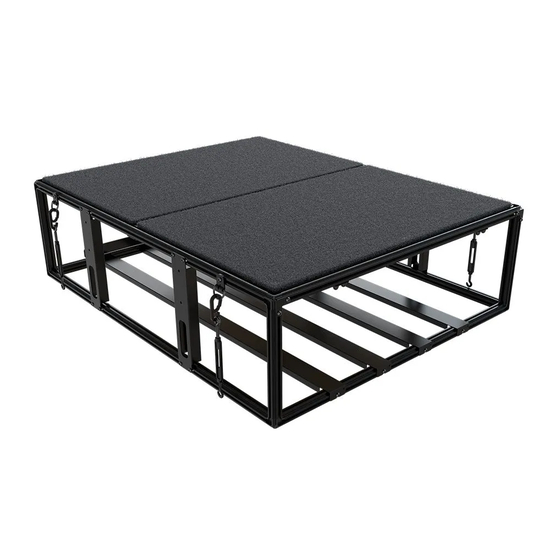
4 wolf pack pro storage
system - NARROW
SSWO012
READ ME !
Thank you for purchasing a Front Runner Modular Storage System.
Before you start, take a moment to familiarize yourself with the Fitting Instructions and the components received.
Refer to Page 2 for a list of all the components, quantities and tools required.
IMPORTANT WARNING!
IT IS CRITICAL THAT ALL FRONT RUNNER PRODUCTS BE PROPERLY AND SECURELY ASSEMBLED AND ATTACHED TO YOUR VEHICLE. IMPROPER ATTACHMENT COULD
RESULT IN AN AUTOMOBILE ACCIDENT, AND COULD CAUSE SERIOUS BODILY INJURY OR DEATH. YOU ARE RESPONSIBLE FOR ASSEMBLING AND SECURING ALL FRONT
RUNNER PRODUCTS TO YOUR VEHICLE. CHECKING THE ATTACHMENTS PRIOR TO USE, AND PERIODICALLY INSPECTING THE PRODUCTS FOR ADJUSTMENT, WEAR AND
DAMAGE. THEREFORE YOU MUST READ AND UNDERSTAND ALL OF THE INSTRUCTIONS AND PRECAUTIONS SUPPLIED WITH YOUR FRONT RUNNER PRODUCT PRIOR TO
INSTALLATION OR USE. IF YOU DO NOT UNDERSTAND ALL OF THE INSTRUCTIONS AND CAUTIONS, OR IF YOU HAVE NO MECHANICAL EXPERIENCE AND ARE NOT THOROUGHLY
FAMILIAR WITH THE INSTALLATION PROCEDURES, YOU SHOULD HAVE THE PRODUCT INSTALLED BY A PROFESSIONAL INSTALLER OR OTHER QUALIFIED PERSONNEL.
SSWO012_REV_A00
1
2024 FRONT RUNNER VEHICLE OUTFITTERS
Advertisement

Related Manuals for Front Runner SSW0012


Summary of Contents for Front Runner SSW0012
- Page 1 IMPORTANT WARNING! IT IS CRITICAL THAT ALL FRONT RUNNER PRODUCTS BE PROPERLY AND SECURELY ASSEMBLED AND ATTACHED TO YOUR VEHICLE. IMPROPER ATTACHMENT COULD RESULT IN AN AUTOMOBILE ACCIDENT, AND COULD CAUSE SERIOUS BODILY INJURY OR DEATH. YOU ARE RESPONSIBLE FOR ASSEMBLING AND SECURING ALL FRONT RUNNER PRODUCTS TO YOUR VEHICLE.
- Page 2 M6 x 10 Button Head Bolt Wood Decking 38 X M6 x 8 Button Head Bolt 46 X M6 Thin Nut NOTE: This Unit is broken down into Sub-Assemblies and is marked accordingly. FIGURE 1.1 SSWO012_REV_A00 2024 FRONT RUNNER VEHICLE OUTFITTERS...
-
Page 3: Sub-Assembly
Extrusion 1025mm Long Corner Rubber Mallet M6 Thin Nut M6 x 12 Hex Bolt FIGURE 2.1 NOTE: Fasteners (Bolts and Nuts) only apply to the Top Frame Assembly. Fasteners to be assembled on both sides. SSWO012_REV_A00 2024 FRONT RUNNER VEHICLE OUTFITTERS... - Page 4 Repeat this process until you have a square of four Extrusions and four Corners. Use the Rubber Mallet to securely fit the corners so they are flush against each Extrusion. This will be the Top Frame. SSWO012_REV_A00 2024 FRONT RUNNER VEHICLE OUTFITTERS...
- Page 5 NOTE: Bottom Frame is Similar to the top frame, but with no pre-loaded fasteners. FIGURE 3.1 Repeat Steps 2.1 - 2.3 to assemble another frame, but leave out the M6 x 12 Hex Bolts and M6 Thin Nuts. This would be the Bottom Frame. SSWO012_REV_A00 2024 FRONT RUNNER VEHICLE OUTFITTERS...
- Page 6 Loosely assemble using M6 x 10 Button Head Bolts (Item 15). Loosely assemble all the Bottom Supports on the opposite side using M6 x 8 Button Head Bolts (Item 17). Tighten all fasteners and put assembly aside. SSWO012_REV_A00 2024 FRONT RUNNER VEHICLE OUTFITTERS...
- Page 7 SUB-ASSEMBLY 3 IN THE BOX TOOLS NEEDED Extrusion 805mm Long Top Frame assembled in Step 2 Joiner Plate M6 x 8 Button Head Bolt M6 Thin Nut M6 X 12 Hex Bolt FIGURE 4.1 SSWO012_REV_A00 2024 FRONT RUNNER VEHICLE OUTFITTERS...
- Page 8 Loosely assemble using two M6 x 8 Button Head Bolts (Item 17). Do this for both sides. Align the centre of the Extrusion with the mark made in 4.1, but do not tighten fasten- ers yet. SSWO012_REV_A00 © 2024 FRONT RUNNER VEHICLE OUTFITTERS...
- Page 9 SUB-ASSEMBLY 4 IN THE BOX TOOLS NEEDED Sub-assembly 3 Corner Bracket Middle Bracket 16 X M6 x 25 Coutersunk Screw Wood Decking FIGURE 5.1 SSWO012_REV_A00 2024 FRONT RUNNER VEHICLE OUTFITTERS...
- Page 10 Repeat Steps 5.1-5.3 to secure the remaining Deck to the frame. NOTE: Do not over tighten - tighten until snug. Fully tighten Joiner from Step 4.3. Tightening Torque: M6 : 8-10Nm / 5.9 ft lb - 7.38 ft lb SSWO012_REV_A00 © 2024 FRONT RUNNER VEHICLE OUTFITTERS...
- Page 11 SUB-ASSEMBLY 5 IN THE BOX TOOLS NEEDED Sub-assembly 4 Spring 12 X M6 Nyloc Nut 10mm 12 X M6 Nut Cap FIGURE 6.1 SSWO012_REV_A00 2024 FRONT RUNNER VEHICLE OUTFITTERS...
- Page 12 Tightening Torque: M6 : 8-10Nm / 5.9 ft lb - 7.38 ft lb Adjust Springs if necessary and tighten all fasteners. Place M6 Nut Caps (Item 24) over each M6 Nyloc Nut. 10mm SSWO012_REV_A00 © 2024 FRONT RUNNER VEHICLE OUTFITTERS...
- Page 13 SUB-ASSEMBLY 6 IN THE BOX TOOLS NEEDED Sub-assembly 5 Turn Buckle Carabiner - Large M6 D-Ring M6 x 10 Button Head Bolt Carabiner - Small FIGURE 7.1 SSWO012_REV_A00 2024 FRONT RUNNER VEHICLE OUTFITTERS...
- Page 14 - and Turn Buckle (Items 11 & 12 or 19) onto the D-Rings for use when installing in the vehicle. Do not tighten fasteners yet, D-Rings should still slide freely in the T-slot. SSWO012_REV_A00 © 2024 FRONT RUNNER VEHICLE OUTFITTERS...
-
Page 15: Main Assembly
MAIN ASSEMBLY IN THE BOX TOOLS NEEDED Sub-assembly 6 Sub-assembly 2 Extrusion 250mm Long Rubber Mallet Side Strut 24 X M6 x 8 Button Head Bolts 28 X M6 Thin Nut Corner Gusset FIGURE 8.1 SSWO012_REV_A00 2024 FRONT RUNNER VEHICLE OUTFITTERS... - Page 16 Load four M6 Thin Nuts (Item 18) into the outer T-Slot on the bottom and top Extrusions parallel to the Bottom Supports, as shown in Fig 8.3. Repeat on the opposite side. SSWO012_REV_A00 © 2024 FRONT RUNNER VEHICLE OUTFITTERS...
- Page 17 Place the Drawer System in the vehicle and center it. Make sure the Turnbuckles will be pulling outward to the existing mounting points in the vehicle to prevent it from moving after it has been secured. SSWO012_REV_A00 © 2024 FRONT RUNNER VEHICLE OUTFITTERS...
- Page 18 Drawer System. Make sure the Drawer System stays in position when doing this. Lock the Turn Buckles with the Nuts supplied with the Turn Buckles. Do this by tightening the Nuts up to the Turn Buckle centre part. SSWO012_REV_A00 © 2024 FRONT RUNNER VEHICLE OUTFITTERS...
- Page 19 Congratulations! You did it. Take a step back and admire your work! Front Runner will not be responsible for any damage caused by the failure to install the product according to these instructions. Please call us if you have any questions about the installation of this product.
Need help?
Do you have a question about the SSW0012 and is the answer not in the manual?
Questions and answers