Advertisement
Quick Links
ENG
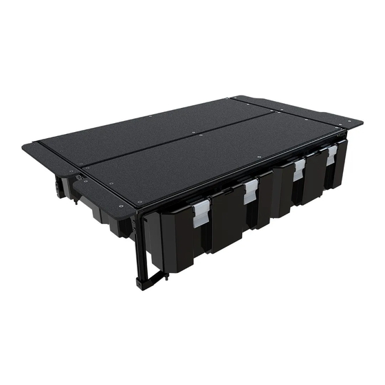
INEOS GRENADIER STORAGE
SYSTEM
SSIG002
READ ME !
Thank you for purchasing a Front Runner Ineos Grenadier Storage System.
Before you start, take a moment to familiarize yourself with the Fitting Instructions and the components received.
Refer to Page 2 for a list of all the components, quantities and tools required.
IMPORTANT WARNING!
IT IS CRITICAL THAT ALL FRONT RUNNER PRODUCTS BE PROPERLY AND SECURELY ASSEMBLED AND ATTACHED TO YOUR VEHICLE. IMPROPER ATTACHMENT COULD
RESULT IN AN AUTOMOBILE ACCIDENT, AND COULD CAUSE SERIOUS BODILY INJURY OR DEATH. YOU ARE RESPONSIBLE FOR ASSEMBLING AND SECURING ALL FRONT
RUNNER PRODUCTS TO YOUR VEHICLE. CHECKING THE ATTACHMENTS PRIOR TO USE, AND PERIODICALLY INSPECTING THE PRODUCTS FOR ADJUSTMENT, WEAR AND
DAMAGE. THEREFORE YOU MUST READ AND UNDERSTAND ALL OF THE INSTRUCTIONS AND PRECAUTIONS SUPPLIED WITH YOUR FRONT RUNNER PRODUCT PRIOR TO
INSTALLATION OR USE. IF YOU DO NOT UNDERSTAND ALL OF THE INSTRUCTIONS AND CAUTIONS, OR IF YOU HAVE NO MECHANICAL EXPERIENCE AND ARE NOT THOROUGHLY
FAMILIAR WITH THE INSTALLATION PROCEDURES, YOU SHOULD HAVE THE PRODUCT INSTALLED BY A PROFESSIONAL INSTALLER OR OTHER QUALIFIED PERSONNEL.
SSIG002_REV_A00
1
2023 FRONT RUNNER VEHICLE OUTFITTERS
Advertisement

Related Manuals for Front Runner INEOS GRENADIER STORAGE SYSTEM SSIG002


Summary of Contents for Front Runner INEOS GRENADIER STORAGE SYSTEM SSIG002
- Page 1 IMPORTANT WARNING! IT IS CRITICAL THAT ALL FRONT RUNNER PRODUCTS BE PROPERLY AND SECURELY ASSEMBLED AND ATTACHED TO YOUR VEHICLE. IMPROPER ATTACHMENT COULD RESULT IN AN AUTOMOBILE ACCIDENT, AND COULD CAUSE SERIOUS BODILY INJURY OR DEATH. YOU ARE RESPONSIBLE FOR ASSEMBLING AND SECURING ALL FRONT RUNNER PRODUCTS TO YOUR VEHICLE.
- Page 2 M8 x 45 Button Head Bolt Completion Deck 01 Completion Deck 02 Completion Deck 03 Back Completion Deck Support (1 LH & 1 RH) NOTE: This Unit is broken down into Sub-Assemblies and is marked accordingly. FIGURE 1.1 SSIG002_REV_A00 2023 FRONT RUNNER VEHICLE OUTFITTERS...
- Page 3 Extrusion 249.3mm Long Rubber Mallet Side Extrusion 724.6mm Long Top Back Extrusion 1129.6mm Long 12 X M6 x 12 Hex Bolt FIGURE 2.1 NOTE: Fasteners (Bolts and Nuts) only apply to the Top Frame Assembly. SSIG002_REV_A00 2023 FRONT RUNNER VEHICLE OUTFITTERS...
- Page 4 Extrusion. This will be the Top Front Frame. The remaining Front Exstrusion (Item 2) and Top Back Extrusion (Item 5) assembled with the Hex Bolts, in Step 2.1 should be kept aside for use in the next steps. SSIG002_REV_A00 2023 FRONT RUNNER VEHICLE OUTFITTERS...
- Page 5 SUB-ASSEMBLY 2 IN THE BOX TOOLS NEEDED Top Front Frame assembled in Step 2 Front Extrusion assembled in Step 2 M6 Thin Nut M6 x 8 Button Head Bolt Joiner Plate FIGURE 3.1 SSIG002_REV_A00 2023 FRONT RUNNER VEHICLE OUTFITTERS...
- Page 6 Head Bolts (Item 16). Do this for both sides. Measure 362mm from the ends of both Side Extrusions and make a mark with a marking pen. Align the centre of the Extrusion with the mark made, but do not tighten fasteners yet. SSIG002_REV_A00 2023 FRONT RUNNER VEHICLE OUTFITTERS...
-
Page 7: M6 Thin Nut 4Mm
Frame assembled in Step 3 Top Back Extrusion assembled in Step 2 10 X M6 Thin Nut 10 X M6 x 8 Button Head Bolt Back Completion Deck Support (1 LH & 1 RH) FIGURE 4.1 SSIG002_REV_A00 2023 FRONT RUNNER VEHICLE OUTFITTERS... - Page 8 15). Do this for both sides. Do not turn the M6 Thin Nut more than once, as a loose assembly is required to slide in the Back Leg Extrusions in the next step. SSIG002_REV_A00 © 2023 FRONT RUNNER VEHICLE OUTFITTERS...
- Page 9 IN THE BOX TOOLS NEEDED Top Front Frame assembled in Step 4 Back Leg Extrusion 224.6mm Long Back Bottom Extrusion 999.6mm Long M6 Thin Nut M6 x 8 Button Head Bolt Joiner Plate FIGURE 5.1 SSIG002_REV_A00 2023 FRONT RUNNER VEHICLE OUTFITTERS...
- Page 10 Top Back Extrusion and the Bottom Back Extrusion (Items 5 & 7), as shown in Fig 5.3. Note the orientation of the Thin Nuts in relation to the frame - placed in the outside T-Slot. SSIG002_REV_A00 © 2023 FRONT RUNNER VEHICLE OUTFITTERS...
- Page 11 Extrusion, but not on the Bottom Back Extrusion. The Bottom Back Extrusion should still slide freely on the Joiner Plate. Tightening Torque: M6 : 8-10Nm / 5.9 ft lb - 7.38 ft lb SSIG002_REV_A00 © 2023 FRONT RUNNER VEHICLE OUTFITTERS...
- Page 12 Frame assembled in Step 5 Front Mounting Bracket Back Mounting Bracket 19 X M6 Thin Nut 19 X M6 x 8 Button Head Bolt Mid Completion Deck Support Front Completion Deck Support FIGURE 6.1 SSIG002_REV_A00 2023 FRONT RUNNER VEHICLE OUTFITTERS...
- Page 13 M6 Thin Nuts in the Front Leg Extrusion (Item 15) as loaded in Step 6.1. Do this for both sides and tighten all fasten- ers. Tightening Torque: M6 : 8-10Nm / 5.9 ft lb - 7.38 ft lb SSIG002_REV_A00 © 2023 FRONT RUNNER VEHICLE OUTFITTERS...
- Page 14 Take note that the Front Mounting Bracket Left and Right are interchange- able to accommodate different Mounting Points of different Models. Tightening Torque: M6 : 8-10Nm / 5.9 ft lb - 7.38 ft lb SSIG002_REV_A00 © 2023 FRONT RUNNER VEHICLE OUTFITTERS...
- Page 15 SUB-ASSEMBLY 6 IN THE BOX TOOLS NEEDED Frame assembled in Step 6 Spring Assembly 12 X M6 Nyloc Nut 10mm 12 X M6 Nut Cap FIGURE 7.1 SSIG002_REV_A00 2023 FRONT RUNNER VEHICLE OUTFITTERS...
- Page 16 269mm measurement. Adjust Springs if necessary and tighten all fasteners. Place M6 Nut Caps (Item 30) over each M6 Nyloc Nut. Tightening Torque: M6 : 8-10Nm / 5.9 ft lb - 7.38 ft lb SSIG002_REV_A00 © 2023 FRONT RUNNER VEHICLE OUTFITTERS...
- Page 17 TOOLS NEEDED Frame assembled in Step 7 Deck Corner Brackets Middle Brackets 16 X M6 x 25 Countersunk Bolts Completion Deck 01 Completion Deck 02 Completion Deck 03 M6 x 20 Countersunk Bolts FIGURE 8.1 SSIG002_REV_A00 2023 FRONT RUNNER VEHICLE OUTFITTERS...
- Page 18 Bolt (Item 11). Repeat for all Middle points of the Deck. Repeat Steps 8.1-8.3 to secure the remaining Deck to the frame. Tightening Torque: M6 : 8-10Nm / 5.9 ft lb - 7.38 ft lb SSIG002_REV_A00 © 2023 FRONT RUNNER VEHICLE OUTFITTERS...
- Page 19 Support Bracket as assembled in Step 6.2. Take Note of the orientation of the Completion Deck in relation to the Frame. Tightening Torque: M6 : 8-10Nm / 5.9 ft lb - 7.38 ft lb FRONT OF FRAME SSIG002_REV_A00 © 2023 FRONT RUNNER VEHICLE OUTFITTERS...
- Page 20 MAIN ASSEMBLY IN THE BOX TOOLS NEEDED Frame assembled in Step 8 Spacer 19 x 22 M8 x 16 x1.6 Flat Washer M8 x 45 Button Head Bolt FIGURE 9.1 FRONT OF VEHICLE SSIG002_REV_A00 2023 FRONT RUNNER VEHICLE OUTFITTERS...
- Page 21 Washer (Item 17) and a M8 x 45 Button Head Bolt (Item 18) on each corner. Tighten all fasteners to the vehicle. Tightening Torque: M8 : 15-20Nm / 11.06 ft lb - 14.75 ft lb SSIG002_REV_A00 © 2023 FRONT RUNNER VEHICLE OUTFITTERS...
- Page 22 Congratulations! You did it. Take a step back and admire your work! Front Runner will not be responsible for any damage caused by the failure to install the product according to these instructions. Please call us if you have any questions about the installation of this product.
Need help?
Do you have a question about the INEOS GRENADIER STORAGE SYSTEM SSIG002 and is the answer not in the manual?
Questions and answers