Advertisement
Quick Links
Depending on the type of installation chosen, not all components supplied will be used. Refer to Page 15 Section
8 on how to set the angle of the Floodlight.
IT IS CRITICAL THAT ALL FRONT RUNNER PRODUCTS BE PROPERLY AND SECURELY ASSEMBLED AND ATTACHED TO YOUR
VEHICLE. IMPROPER ATTACHMENT COULD RESULT IN AN AUTOMOBILE ACCIDENT, AND COULD CAUSE SERIOUS BODILY
INJURY OR DEATH TO YOU OR TO OTHERS. YOU ARE RESPONSIBLE FOR ASSEMBLING AND SECURING ALL FRONT RUNNER
PRODUCTS TO YOUR VEHICLE, CHECKING THE ATTACHMENTS PRIOR TO USE, AND PERIODICALLY INSPECTING THE
PRODUCTS FOR ADJUSTMENT, WEAR, AND DAMAGE. THEREFORE, YOU MUST READ AND UNDERSTAND ALL OF THE
INSTRUCTIONS AND CAUTIONS SUPPLIED WITH YOUR FRONT RUNNER PRODUCT PRIOR TO INSTALLATION OR USE. IF YOU DO
NOT UNDERSTAND ALL OF THE INSTRUCTIONS AND CAUTIONS, OR IF YOU HAVE NO MECHANICAL EXPERIENCE AND ARE NOT
THOROUGHLY FAMILIAR WITH THE INSTALLATION PROCEDURES, YOU SHOULD HAVE THE PRODUCT INSTALLED BY A
PROFESSIONAL INSTALLER OR OTHER QUALIFIED PERSONNEL.
REV_A03
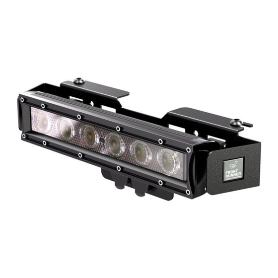
LED 10 FLOODLIGHT unit
"
IMPORTANT WARNING!
1
RRAC054 / RRAC058
INSTALL TIME: 1 Hour
Advertisement

Related Manuals for Front Runner RRAC054


Summary of Contents for Front Runner RRAC054
- Page 1 VEHICLE. IMPROPER ATTACHMENT COULD RESULT IN AN AUTOMOBILE ACCIDENT, AND COULD CAUSE SERIOUS BODILY INJURY OR DEATH TO YOU OR TO OTHERS. YOU ARE RESPONSIBLE FOR ASSEMBLING AND SECURING ALL FRONT RUNNER PRODUCTS TO YOUR VEHICLE, CHECKING THE ATTACHMENTS PRIOR TO USE, AND PERIODICALLY INSPECTING THE PRODUCTS FOR ADJUSTMENT, WEAR, AND DAMAGE.
- Page 2 GET ORGANIZED You will need: Here is what you are looking at: 13 mm Flat Wrench 4 mm Hex Key (Front/Rear Mounting Option) Item # Quantity Description 5 mm Hex Key 10" LED FLOODLIGHT Side Cutter D-SHAPED NUT Wire Stripper M6 NYLOC NUT MOUNTING ARM Crimping Tool...
- Page 3 Hella Plugs found on the front of the Floodlight's mounting bracket (Refer to Pages 8 & 9, Steps 3F & 3G). Should you wish to purchase the Front Runner Extension Cable, the Part Number / Item Code is ECOM076.
- Page 4 Prepare Wiring Suggested Method ... CONT Strip one end of the insulation on the red wire from Step 2C back 5 mm and crimp the Flag Terminal (Item 18) to the wire as shown below. Crimp Crimp Strip insulation back 5 mm Red wire from Step 2D Fit an Insulating Boot (Item 19) over the crimped Flag Terminal as shown below.
- Page 5 Prepare Wiring Suggested Method ... CONT Feed the Floodlight's electrical cable through the the hole in the Rubber Grommet inserted in Step 2F as shown below. ( H ) Following the steps below, strip and twist the red wires together as shown. Strip back the insulation by 10 mm on the Twist together RED wire of lights power cable.
- Page 6 Prepare Wiring Suggested Method ... CONT ( ) I Slide an Insulating Boot (Item 19) over the twisted pair of red wires from Step 2H and crimp a Flag Terminal (Item 18) onto the end of the twisted pair as shown. ( J ) Slide the Insulating Boot over the Flag Terminal from Step 2I as shown.
- Page 7 (Items 3 & 11). The Mounting Arms must face down as shown. DO NOT US THE RUBBER MOUNTS SUPPLIED WHEN USING THE FRONT RUNNER BRACKET Insert the D-Shaped Nut (Item 2) into each end of the light as shown. The domed side of the nut must go to the outside of the light.
- Page 8 Prepare for light install Cut Off Looking at the two Hella Plugs (Item 17), cut off the outer "tab" on each using a pair of side cutters. DO NOT CUT OFF THE MIDDLE TAB Bend the "tab" on the Earth Plate (Item 15) to 90 degrees as shown below. Bend "tab"...
- Page 9 Prepare for light install Connect the Floodlight to the Hella Plugs as shown below. The two red wires go onto the center "tabs" of the Hella Plugs and the black wire goes onto the "tab" on the Earth Plate. Red Wire to "tab" in center of Hella Plug Black wire to "tab"...
- Page 10 Prepare for light install ( i ) The Floodlight Unit may be mounted on the front, rear, left or right hand side of your Rack. When mounting on the side of the rack, the Floodlight Unit may be mounted inline with a slat (recommended) or between two slats as shown below.
- Page 11 Side Mounting Inline with a Slat Decide on which side of the Rack you would like to install the Floodlight Unit. On the chosen side, slide two M8 Nyloc Nuts (Item 10) dome side down into the U-channel through the gap in the corner of the Tray as shown.
- Page 12 Side Mounting Between two Slats Decide on which side of the Rack you would like to install the Floodlight Unit. On the chosen side, slide three M8 Nyloc Nuts (Item 10) dome side down into the U-channel through the gap in the corner of the Rack as shown.
- Page 13 FRONT REAR Mounting When mounting on the front or rear of the Rack, remove one of the appropriate corners by loosening the M6 Button Head Bolt (as indicated by the arrow) and pulling the Corner free from the Rack. Insert two M8 Nyloc Nuts (Item 10) into each of the "U"-channels as shown. 2 x Nyloc Nuts - Dome side facing down 2 x Nyloc Nuts - Dome side facing up Place the Floodlight Unit over the Rack (Hella Plugs facing down) in the desired position.
- Page 14 install Floodlight Slimline Rack Place the Floodlight Bracket over the side of the rack (Hella Plug cut-outs facing down) in the desired position. Mark the position of hole set "A" or "B" onto the side of the Rack. Remove the Floodlight Bracket and drill a 6 mm hole on each of your two markings.
-
Page 15: Adjusting The Angle
Loosen the two M6 Bolts (as indicated by the arrows) enough to allow the Floodlight to rotate and adjust the Floodlight up or down until the desired angle has been achieved. Tighten the two M6 Bolts INSTALL OTHER VEHICLE AND RACK ACCESSORIES Now's the time to visit your favorite Front Runner dealer in person or online. REV_A03...
Need help?
Do you have a question about the RRAC054 and is the answer not in the manual?
Questions and answers