Table of Contents
Advertisement
Quick Links
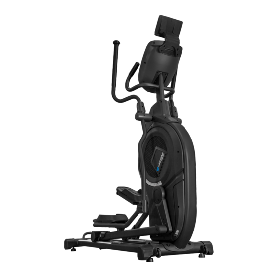
XT-44
Cross Trainer
USER MANUAL
Read all instructions carefully before using this product.
Retain this owner's manual for future reference.
IMPORTANT
All nuts and bolts are to be checked and tightened on a regular basis. This includes pedals and
other moving parts. Failure to do so may cause damage to your threads and void your warranty.
NOTE:
Product may vary slightly from the item pictured due to model upgrades. This manual may be subject to updates or changes.
Up to date manuals are available through our website at www.lifespanfitness.com.au
Advertisement
Table of Contents

Related Manuals for LifeSpan XT-44


Summary of Contents for LifeSpan XT-44
- Page 1 XT-44 Cross Trainer USER MANUAL Read all instructions carefully before using this product. Retain this owner’s manual for future reference. IMPORTANT All nuts and bolts are to be checked and tightened on a regular basis. This includes pedals and other moving parts. Failure to do so may cause damage to your threads and void your warranty.
-
Page 2: Table Of Contents
TABLE OF CONTENTS Important Safety Instructions ....... 03 II. Care Instructions ..........04 III. -
Page 3: Important Safety Instructions
I. IMPORTANT SAFETY INSTRUCTIONS WARNING: Read all instructions before using this machine. It is important your machine receives regular maintenance to prolong its useful life. Failing to regularly maintain your machine may void your warranty. Please keep this manual with you at all times. •... -
Page 4: Care Instructions
• Always keep this instruction manual and assembly tools at hand for reference. • The equipment is not suitable for therapeutic use. • The pulse or heart rate sensors are not medical devices. Various factors, including the user’s movement, may affect the accuracy of heart rate readings. The pulse sensors are intended only as exercise aids in determining heart rate trends in general. -
Page 5: Exploded Diagram
III. EXPLODED DIAGRAM 50 44 18 68 EXPLODED DIAGRAM |... - Page 6 50 20 | EXPLODED DIAGRAM...
-
Page 7: Parts List
IV. PARTS LIST Some items on this list may come pre-installed on your equipment. If you feel like you’re missing anything, please double check your equipment. Description Specs Description Specs Basic frame Tensioning wheel Main frame Belt pulley Console fix frame Wheel Upper swing arm-left Pulley... - Page 8 Description Specs Description Specs Philips C.K.S. M5x15 Brake wire L-450xΦ5x Φ1.2xM5 full thread bolt Φ25x220 Allen pan head M6x12 Crank axle group full thread bolt Communication Wire L-1300mm Allen pan head M6x50x20 Allen half thread bolt M12x75x20 half thread bolt Hand pulse L-650mm Allen pan head...
- Page 9 ASSEMBLY PARTS LIST Description Specs Description Specs Φ10xΦ22x2.0 Basic frame Flat washer Φ10.5xR100xt2.0 2 Main frame Curved washer Φ8.5xR25xt2.0 Console fix frame Curved washer Φ8 Upper swing arm-left Spring washer Φ10 Upper swing arm-right Spring washer Bottom swing arm-left Hex self-locking nut Bottom swing arm-right Philips C.K.S.
- Page 10 1. iPad Holder 2. Console 3. Handlebar 4. Upper Swing Arm 5. Air Outlet 6. Pedal Support 7. Pedal 8. Basic Frame HARDWARE PACK LIST Description Specs Description Specs Allen cylinder head M10x70x20 Allen pan head M8x20 half thread bolt full thread bolt Φ8.5xΦ20xt1.5 Flat washer...
- Page 11 Ø8.5 x Ø20 x t1.5-4 Ø8.2 x Ø25 x t2.0-4 Ø10 x Ø22 x t2.0-4 Ø10.5 x R100 x t2.0-2 Ø8-3 Ø10-6 Ø8.5 x R25 x t2.0-7 M8-10 M5 x 15-12 Ø9.4 x 23.5-M6-2 ST4 x 16-10 M8 x 20-5 M8 x 40 x 20-6 M10 x 70 x 20-4 M8 x 60 x 20-4...
-
Page 12: Assembly Instructions
V. ASSEMBLY INSTRUCTIONS STEP 1 STEP 2 1. Place the main frame (2) on the basic frame 1. Pull out the communication line (88) from (1), secure with 2pcs Allen cylinder head half the hole of console fix group (3). thread screw (95), 2pcs spring washer (52), 2. - Page 13 69 20 STEP 3 STEP 4 1. Add some oil to the axle of the main frame. 1. Add some oil to the axle of the main frame. Assemble the bottom swing arm (6) on the Place the pedal group left (8) on the track, main body, secure with 1pc Allen pan head secure the pedal group left (8) by 1pc flat full thread bolt (68), 1 pc spring washer (51)
- Page 14 STEP 5 STEP 6 1. Install the Roll wheel position stopper (85) 1. Connect the communication line (88), and on Pedal group-left (8) with an Allen Pan hand pulse communication line (90) with head half thread bolt (70) and a hex self- console communication line.
-
Page 15: Computer Operation
VI. COMPUTER OPERATION CONSOLE OPERATION INSTRUCTION BUTTON FUNCTIONS • To test heart rate recovery status. RECOVERY • In STOP mode, press this button to select function or confirm all setting MODE values. • To select workout program. PROGRAM • To test the Body Fat% (5.0%~ 50%) and BMI (0~50). BODY FAT •... - Page 16 DISPLAY FUNCTION • Count up – no preset target, time will count up from 0:00. TIME • Count down – with preset target, time will count down from preset to 0, then system STOP. And system alarm 8s with 4 sounds in every second. •...
- Page 17 OPERATION PROCEDURE 1. POWER ON Connect power (press RESET key for 2s), buzzer sound for 1s and LED will full display 2s (Drawing 1) then display wheel diameter and KM (or ML) in middle window and "E" (or "A") in CALORIE window (Drawing 2).
- Page 18 Drawing 9 Drawing 10 Drawing 11 Drawing 12 Drawing 13 4.1. MANUAL MODE In main menu, press "P" (PROGRAM) key or press "+"/"-" to select MANUAL, press MODE to enter MANUAL mode. Before exercising, user needs to adjust the following values: TIME: is blinking (Drawing 14).
- Page 19 Drawing 14 Drawing 15 Drawing 16 Drawing 17 4.2. PROGRAM MODE Press RESET key to go to main menu. Press "+" or "-" key and press MODE to enter PROGRAM mode. Entering Program mode, there are total 12 program profiles (P1~P12) (Drawing 18~29) for selection. Press "+"...
- Page 20 Drawing 18 Drawing 19 Drawing 20 Drawing 21 Drawing 22 Drawing 23 Drawing 24 Drawing 25 Drawing 26 Drawing 27 Drawing 28 Drawing 29 Drawing 30 Drawing 31 20| COMPUTER OPERATION...
- Page 21 Drawing 32 Drawing 33 4.3. USER (PROGRAM) MODE Press RESET key to go to main menu. Press "+" or "-" key and press MODE to enter USER program. User may create their own profile in this mode. The first blue dot of the profile will start blinking, then press "+"...
- Page 22 4.4. H.R.C. MODE Press RESET key to go to main menu. Press "+" or "-" button and press MODE to enter H.R.C. mode. In H.R.C. mode, press "+" or "-" button to choose: 55%, 75%, 90% or TAG. The LED will be blinking. User may choose different target heart rates, the preset value system self-calculated based on user input AGE will display in PULSE window (Drawing 34~37).
- Page 23 Drawing 42 Drawing 43 5. RECOVERY MODE If there is no pulse signal input to console, it is invalid to press RECOVERY button. When pulse value appears on screen, press RECOVERY button to start test. Keep both hands hold on hand grips (or wear chest belt).
- Page 24 Press BODY FAT button again to go back to previous workout status. ※Error code display during measurement: E-1--- user not hold hand grips correctly (Drawing 49) E-4--- Body Fat% exceed setting range (5.0%~ 50%). (Drawing 50) NOTE: A. When user press RESET button for 2 seconds for TOTAL RESET, console enter to START mode, buzzer alarm 1s, all LED display for 2s, then go to setting mode.
-
Page 25: Exercise Guide
VII. EXERCISE GUIDE PLEASE NOTE: Before beginning any exercise program, consult your physician. This is important especially if you are over the age of 45 or individuals with pre-existing health problems. The pulse sensors are not medical devices. Various factors, including the user’s movement, may affect the accuracy of heart rate readings. - Page 26 WARM-UP/STRETCHING EXERCISES A successful exercise session begins with warming up exercises and ends with exercises for cooling down and relaxing. These warming up exercises prepare your body for the subsequent demands made upon it. The cooling down / relaxation period after the exercise session ensures that you do not experience any muscular problems.
- Page 27 WORKOUT GUIDELINES HEART RATE MAXIMUM TARGET ZONE COOL DOWN 20 25 30 35 40 45 50 55 60 65 70 This is how your pulse should behave during general fitness exercise. Remember to warm up and cool down for a few minutes. EXERCISE GUIDE |...
-
Page 28: Warranty
Any claim against this warranty must be made through your original place of purchase. Proof of purchase is required before a warranty claim may be processed. If you have purchased this product from the Official Lifespan Fitness website, please visit https://lifespanfitness.com.au/warranty-form For support outside of warranty, if you wish to purchase replacement parts or request a repair or service, please visit https://lifespanfitness.com.au/warranty-form and fill in our Repair/Service... -
Page 29: Hand Pulse Technology
IX. HAND PULSE TECHNOLOGY This product comes equipped with hand pulse sensors which are used to pick up tiny EKG/ECG signals that run through the body when your heart beats. These electrical EKG/ECG signals are very small and must be amplified 1000 times to make the signal viable for the computer to display your pulse. To ensure proper operation: •... - Page 32 WWW.LIFESPA NF ITN ES S.COM.AU...
Need help?
Do you have a question about the XT-44 and is the answer not in the manual?
Questions and answers