Table of Contents
Advertisement
Quick Links
Read all instructions carefully before using this product.
Retain this owner's manual for future reference.
IMPORTANT
All nuts and bolts are to be checked and tightened on a regular basis. This includes pedals and
other moving parts. Failure to do so may cause damage to your threads and void your warranty.
NOTE:
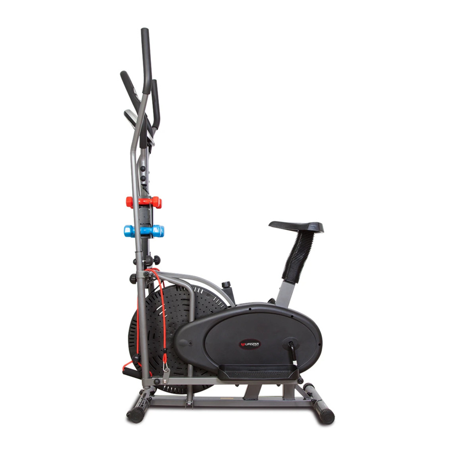
Product may vary slightly from the item pictured due to model upgrades. This manual may be subject to updates or changes.
Up to date manuals are available through our website at www.lifespanfitness.com.au
X-02
Cross Trainer
USER MANUAL
Advertisement
Table of Contents

Related Manuals for LifeSpan X-02


Summary of Contents for LifeSpan X-02
- Page 1 X-02 Cross Trainer USER MANUAL Read all instructions carefully before using this product. Retain this owner’s manual for future reference. IMPORTANT All nuts and bolts are to be checked and tightened on a regular basis. This includes pedals and other moving parts. Failure to do so may cause damage to your threads and void your warranty.
-
Page 2: Table Of Contents
TABLE OF CONTENTS Important Safety Instructions ....... 03 II. Care Instructions ..........04 III. -
Page 3: Important Safety Instructions
I. IMPORTANT SAFETY INSTRUCTIONS WARNING: Read all instructions before using this machine. It is important your machine receives regular maintenance to prolong its useful life. Failing to regularly maintain your machine may void your warranty. Please retain this manual properly for future reference. •... -
Page 4: Care Instructions
• Always keep this instruction manual and assembly tools at hand for reference. • The equipment is not suitable for therapeutic use. • The pulse or heart rate sensors are not medical devices. Various factors, including the user’s movement, may affect the accuracy of heart rate readings. The pulse sensors are intended only as exercise aids in determining heart rate trends in general. -
Page 5: Parts List
III. PARTS LIST Name Name Main Frame Sensor Front stabilizer Crank Connecting tube Rear stabilizer 4L/R Swing bar 1pr. Washer Arc washer 2-Slot nut Φ10x1.5xΦ25xR28 Collar ball Pedal tube 1pr. Collar housing 6L/R 7L/R Handle bar 1pr. Hex nut 8L/R Chain cover 1pr. - Page 6 Name Name Adjusting washer Φ10.5x3xΦ18 Chain wheel Handlebar post Hex bolt M8x2x145 Cross taping screw ST4.8x40 Flat washer Washer Nylon nut M8 D shape washer Arc washer Φ28xΦ16.2x14xB5 d8x1.5x Φ 19xR13 Allen bolt M10x18 Plastic cap S19 Pulse sensor wire 3-Slot Nut Hex bolt M6xL45xL12 Pulse extension wire...
-
Page 7: Exploded Diagram
IV. EXPLODED DIAGRAM EXPLODED DIAGRAM |... -
Page 8: Assembly Instructions
V. ASSEMBLY INSTRUCTIONS STEP 1 Install the Stabilizers 1. Attach the Stabilizer (3) onto the Main frame (1), secure with the Carriage bolts (46), Arc washers (5), and Acorn nuts (47). Repeat the steps for the second stabilizer (2) | ASSEMBLY INSTRUCTIONS... - Page 9 STEP 2 Install the Coupler bars & Pedal arms 1. Remove Adjusting bolt (24), D shape washer (56), Spring washer (52) and Bolts (57) from the Handle bar shaft (12) on one side. 2. Mount one Coupler bar (4R) to the Main section, then attach the other side’s Coupler bar (4L). 3.
- Page 10 STEP 3 Install the Pedals 1. Attach the Pedals (11 R&L) to the Pedal arms (6 R&L) respectively. Secure in place with the Hex bolts (44) and Nuts (45). STEP 4 Install the Handle bars 1. Insert the Handle bars (7L&7R) into the Swing bars (4L/R) accordingly.
- Page 11 STEP 5 Install the Saddle and Saddle post 1. Place the Saddle (65) over the Saddle post (68). Secure in place with the Flat washers (66) and Nylon nuts (67). 2. Slide the Decorative Sleeve (69) onto the Saddle post, then insert the Saddle post (68) into the Main section (1);...
- Page 12 37 26 STEP 6 Install the Computer post 1. Insert the Connecting tubes (28) to the Main section (1). Secure in place with Knobs (17). 2. Attach the Computer post (73) onto the Connecting tubes (28). Secure with Flat washers (41) and Hex bolts (43). Cover the Bolts with Caps (71). 3.
- Page 13 STEP 7 Install the Computer 1. Connect the Pulse sensor Wire (58) and Pulse extension wire (79). Secure the Handlebar (49) to the Handlebar post (73) with the Hex bolt (53), Nylon nut (75) and Arc washer (76). Cover the Cap (71&89) 2.
-
Page 14: Tension Adjustment
VI. TENSION ADJUSTMENT TENSION ADJUSTMENT The assembly of your Elliptical Trainer is now complete. As you try your exercises for the first time, you should adjust the tension to the correct level before you begin your full workout. Turning the adjustment knob allows you to change the tension level and vary the intensity of your workout as you exercise. -
Page 15: Display Manual
VII. DISPLAY MANUAL FUNCTION BUTTONS This key lets you to select and lock on to a desired function. Holding down the mode MODE button will reset all functions to 0. Sets data for "TIME", "DISTANCE", and "CALORIES" when not in scan mode. Push down to reset time, distance and calories values to 0. - Page 16 SPECIFICATIONS Auto Scan Every 4 seconds Running Time 00:00-99:59 Current speed 0.0~999.9 KM FUNCTION Trip Distance 0.0~999.9 KM Total distance(ODO) 0.0~999.9 KM Calories 0.0~999.9 Kcal Pulse Rate 40~240BPM Battery type 2 pcs of size - AA or UM - 3 Operating temperature C~+40 Storage temperature...
-
Page 17: Warranty
Any claim against this warranty must be made through your original place of purchase. Proof of purchase is required before a warranty claim may be processed. If you have purchased this product from the Official Lifespan Fitness website, please visit https://lifespanfitness.com.au/warranty-form For support outside of warranty, if you wish to purchase replacement parts or request a repair or service, please visit https://lifespanfitness.com.au/warranty-form and fill in our Repair/Service... -
Page 18: Hand Pulse Technology
IX. HAND PULSE TECHNOLOGY This product comes equipped with hand pulse sensors which are used to pick up tiny EKG/ECG signals that run through the body when your heart beats. These electrical EKG/ECG signals are very small and must be amplified 1000 times to make the signal viable for the computer to display your pulse. To ensure proper operation: •... - Page 20 WWW.L IF ESPAN F ITNE S S . COM . A U...
Need help?
Do you have a question about the X-02 and is the answer not in the manual?
Questions and answers