Advertisement
Quick Links
HMD
Instruction Manual
( HDA300A )
Thank you for using products.
●
Please read this manual carefully prior to use the sensor.
●
1
OUTLINE
The HD Series sensors directly detect infrared rays radiated from an
object heated to a high temperature and output signals, and a set of
sensors is composed of an amplifier unit and a receiver. Receivers
come in two different types : cord connection (direct reception) and
fiber optic (detachable/fixed fiber optic unit) types. Also the cord
connection (direct reception) type includes high-temperature and low-
temperature detection types. The operation mode can be selectable
between on-delay, off-delay, one-shot and timer disabled with the
operation setting DIP switch. In addition a DIN standard rail of 35mm
in width may be used for securing the socket.
2
DETECTION ABILITY
Part numbers and detection temperature
Optical
Amplifier unit
receiver
HD301A
HD601N
H D A 3 0 0A
HD400
HD502F
3
DETECTION FIELD OF VIEW CHARACTERISTICS (Typical example)
Cable type
●
HD301A : Aboutφ30mm Aboutφ70mm
Model HD301A
HD601N : Aboutφ25mm Aboutφ50mm
Model HD601N
0
0.5m
Fiber type
●
HD400+ fiber optic cable
Model HD400
HD502F
About
Model HD502F
φ8mm
0
20mm
4
SPECIFICATIONS
Specifications (Detector)
Models
H D3 0 1A
HD6 0 1 N
Wiring
Flying lead 20m length
Ambient
−25 to +70℃
temperature
Ambient
35 to 85%RH
humidity
Withstand voltage
Case grounded
Insulation resistance
Protection
IP66
PHOTOSENSOR
Detection temperature
Fiber optic unit
at a coverage ratio of
ε
100% (
370℃ min.
650℃ min.
GT205(0.5m)
430℃ min.
GT21(1m)
440℃ min.
GT22(2m)
460℃ min.
GT23(3m)
490℃ min.
560℃ min.
Aboutφ140mm
Aboutφ210mm
Aboutφ100mm
Aboutφ150mm
1m
2m
3m
HD400+ fiber optic cable + lens unit
(FA51,52)
About
About
About
About
φ21mm
φ43mm
φ52mm
φ87mm
φ17mm
50mm
100mm
300mm
500mm
Fiber optic type
HD4 0 0
HD5 0 2F
Flying lead 20m
Flying lead 2m
−25 to +70℃
Fiber unit −20 to +200℃
Fiber(+70℃)
35 to 85%RH
Fiber unit 95%RH max.(70℃ min. 20%RH max.)
1500VAC for 1 minute
Case grounded
500VDC mega 20MΩ min.
IP40
IP66
T A K E N A K A E L E C T R O N I C
I N D U S T R I A L C O . , L T D .
Head office
Telephone
FAX
(Amplifier)
Model
Power supply
Current consumption
Output mode
Rating
Light reception (for detection of heated material) : Selectable ON/OFF operation
Operation mode
Timer
Time
Response time
Wiring
Protection
5
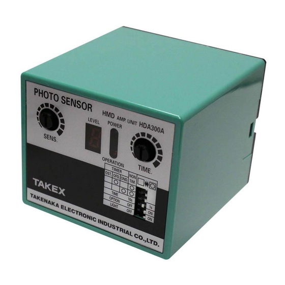
PANEL DESCRIPTION (HDA300A)
①
=0.8 Fe)
②
①
SENS.
Sensitivity adjustment volume
Turning right (clockwise) increases the sensitivity and decreases
the detection temperature.
②
LEVEL
Level indicator : Provides digital indication of the received light
intensity. The preset operation level is approx. 2.5.
"H" is shown for level 9 or higher, indicating saturation.
LEVEL 5 : Double the operation level
LEVEL H : Over quadruple the operation level.
③
POWER
Power indicator : Illuminates while the power is supplied.
④
OPERATION
Operation indicator of light reception : Illuminates for light reception
(detection).
⑤
TIME
Timer adjustment volume : Turning right (clockwise) increases the time.
Operation setting DIP switch :
Used to set the timer mode/operation mode.
TIMER
(Turn the switch left for OFF and right for ON)
NON
OND TIM
OST OFD
← Sw 1, 2 : Timer operation mode setting is made
○
○
by the combination of two switches.
○
○
1s or 10s.
TIME
10s
OPTION
OFF
Ensure that it is always OFF when using.
← Sw 5 :Turn OFF to invert the output logic.
LIGHT
OFF
(The operation DIP switch settings shown above indicate the factory settings.)
6
ADJUSTMENT
For easy adjustment, disable the setting of
the timer mode (NON TIM Sw 1 : ON, Sw 2 : ON).
① Turn the sensitivity adjustment volume on the amplifier unit (SENS.)
right all the way to the maximum sensitivity (clockwise).
② Adjust the sensitivity in the following cases :
1. Sensor activated by the external light.
2. Sensor activated sooner by reflection when high-temperature
detection object approaches. Sensor stays activated due to
reflection even after the heated material has passed.
In any of the cases above, change the location of the receiver or
decrease the sensitivity. When decreasing the sensitivity, adjust so
as to achieve the level indication of "5" or higher at the time of detection.
: 5 - 22 Higashino Kitainoue-cho, Yamashina - ku,
: Kyoto 607 - 8141, Japan
: +81 - 75 - 581 - 7111
: +81 - 75 - 581 - 7118
HDA300A
AC100/110V・AC200/220V ±10%, 50/60Hz
5VA Max.
Relay output/Voltage output
Relay output : 1C AC250V 5A (Max.) (resistive load)
Voltage output : 12VDC 5mA (Max.)
Timer selectable
On-delay, Off-delay, One-shot and None timer selectable
0.1 to 1s /1 to 10s selectable
Relay output : 25ms, Voltage output : 3ms
Terminal block (screw diameter : 3.5mm)
IP20
□
□
Select the timer range between up to
← Sw 3 :
□
1s
Option switch.
□
ON
← Sw 4 :
□
ON
Sens. Down
③
⑤
④
Operation setting DIP switch
Sens. Up
1/4
ABH - HS - 0112 - 2
Advertisement

Related Manuals for Takex HDA300A


Summary of Contents for Takex HDA300A
- Page 1 I N D U S T R I A L C O . , L T D . Instruction Manual : 5 - 22 Higashino Kitainoue-cho, Yamashina - ku, Head office : Kyoto 607 - 8141, Japan ( HDA300A ) : +81 - 75 - 581 - 7111 Telephone : +81 - 75 - 581 - 7118 (Amplifier) Thank you for using products.
- Page 2 OPERATION ■ External gate (external synchronization) ■ Timer operation (one-shot)(OST Sw 1 : OFF Sw 2 : OFF Sw 5 : ON) Terminals No. 12 and 13 are for external gate. When not using external gate, leave the terminals open. Power Short-circuiting terminals No. 12 and 13 disables the light reception Start-up time of approx. 2s max. (the time for stabilization of the internal power supply) is required. operation. Provide contact or open collector for operation. OPEN(H) External gate CLOSE(L) Present DIODE Detection object Not present Output 0V ■ Output circuit t 1 t 1 +V 24V t 1:Response delay time = 25ms max. for relay output, 3ms max. for voltage Light reception output Output transistor:OFF(LIGHT ON Sw5 : ON) 1.5k T:Timer time t :Minimum trigger time = 3ms min. (minimum duration of Output transistor:ON(LIGHT OFF Sw5 : OFF) light reception that enables trigger acceptance) Residual voltage when with the output transistor ON : 1.5V max. ZD12V WIRING (1) Be sure to limit the length of the receiver cable within the length of the cable Voltage output 12VDC Receiver 5mA(MAX)...
- Page 3 INSTALLATION LOCATION Minimum detection object diameter Indicates the thickness (diameter) of the detection heated material ■ Take note of the reflection. against the heated material temperature. For example, when HD301A is If the detection object (heated material) is large and heated to a used as the receiver, the lowest detectable temperature of a steel bar high temperature, the radiation may be reflected on the rollers, of φ20 is approx. 440℃ at a setting distance of 1m. manipulator, side guide of the line, etc. when the material The data only refers to specific setting distance. For other setting approaches and the receiver may be activated even if the material distances, multiply the ratio of each setting distance (ratio with is outside of the detection field of view. reference to the respective setting distance data) by the diameter of the detection heated material in the data. For example, when HD301A is used at a distance of 2m, multiply the diameter of the detection heated material in the data by 2, since the setting distance 2m is double 1m. HD301A HD301A HD601N HD601N The effect of this reflection depends on the state of the reflection Set distance 1m Set distance 1m Set distance 1m Set distance 1m surface, type of the heated material, location of the receiver, etc. however the reflection may become equivalent to the heated material of 500 to 700℃ if it is as large as an ingot or slab, etc. In such a place, install the receiver so as to ensure that the reflection surfaces such as rollers, etc. are out of the detection field of view. Set distance 0.5m Set distance 0.5m Set distance 0.5m Set distance 0.5m ■ External light Visible light rays are completely cut off. However do not install the receiver in a location where rays of sunlight, incandescent lamps, etc., φmm 1000 which have an infrared range, enters the receiver directly or by reflection.
- Page 4 φ 4.2 mounting hole provided) (for M4) 4.2×5.2 long hole (Sensor) model HD502F φ 2.6 φ 1.5 2- φ 2.6 hole Cord 0.3㎜ ×1 core 2m * Do not bend 5 2.8 3 3 3 (max) (Amplifier) model HDA300A 60±2 mounting hole (elongate) DIN rail 6 (max) 35㎜ (Fiber) GT2 series (3) Model Length GT205 0.5m φ 8 φ 8 GT21 1m...
Need help?
Do you have a question about the HDA300A and is the answer not in the manual?
Questions and answers