
Subscribe to Our Youtube Channel
Related Manuals for Dinolift 120T


Summary of Contents for Dinolift 120T
- Page 1 DINO ® OPERATING INSTRUCTIONS ® Raikkolantie 145 FI-32210 LOIMAA T. +358 2 762 5900 F. +358 2 762 7160 dino@dinolift.com www.dinolift.com...
- Page 2 DINO 120T...
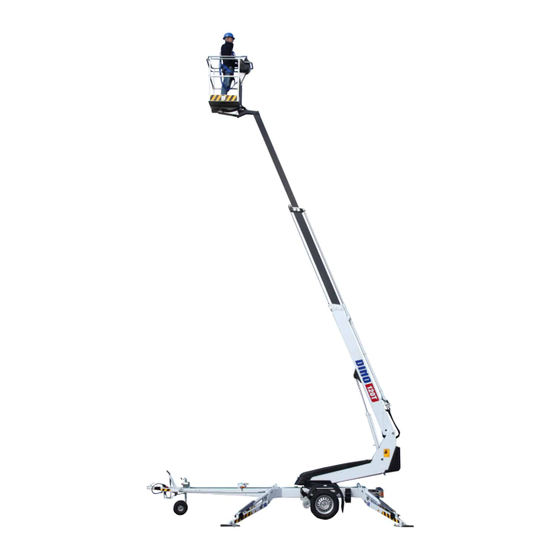
- Page 3 DINO 120T OPERATING INSTRUCTIONS 120003 Valid from serial number...
-
Page 4: Table Of Contents
DINO 120T CONTENTS REACH DIAGRAM........................6 TECHNICAL SPECIFICATION ....................7 GENERAL SAFETY REGULATIONS ..................8 REGULAR INSPECTION ......................10 WORKSITE INSPECTION ......................11 OPERATION OF SAFETY DEVICES ..................12 OPERATING CONTROLS......................14 OPERATING CONTROLS ON CHASSIS CONTROL PANEL..........14 OPERATING CONTROLS ON THE PLATFORM ..............16 MEASURES TO BE TAKEN IF THE LIFT IS AT RISK OF LOSING ITS STABILITY .. - Page 5 CHASSIS CONTROL CENTRE (LCB), OTHER ITEMS............67 PLATFORM CONTROL CENTRE (UCB), OTHER ITEMS ............. 68 LIMIT-SWITCHES........................68 ELECTRIC COMPONENTS 120T 120003 -> ................69 ELECTRIC DIAGRAM 120T 120003 -> ..................71 HYDRAULIC COMPONENTS 120001 -> ................82 HYDRAULIC DIAGRAM 120003-> ..................83...
-
Page 6: Reach Diagram
DINO 120T REACH DIAGRAM 120 kg 265 lb... -
Page 7: Technical Specification
DINO 120T TECHNICAL SPECIFICATION Max. working height 12,0 m Max. platform height 10,0 m Max. outreach 7,9 m Boom rotation continuous Turn area refer to reach diagram Support width 3,60 m / 3,90 m Transport width 1.72 m Transport length... -
Page 8: General Safety Regulations
DINO 120T GENERAL SAFETY REGULATIONS Make yourself familiar with these operation instructions before using the lift! Keep these operating instructions in the place reserved for them. Make sure that all users of the lift are familiar with these instructions. Advice the new users and strictly follow all instructions given by the manufacturer. - Page 9 DINO 120T Do not use ladders, steps or other similar equipment on the platform. Never throw any objects from the platform. The lift must not be used for transferring goods or persons between different floors or working levels. Always make sure before lowering the platform that the area on the underside is clear of any obstructions.
-
Page 10: Regular Inspection
DINO 120T REGULAR INSPECTION A thorough inspection of the lift must be carried out at least once every twelve (12) months. The inspection shall be carried out by a technically trained person who is familiar with the operation and structure of the lift. -
Page 11: Worksite Inspection
DINO 120T WORKSITE INSPECTION 1. General Is the lift suited for the intended job? Is the performance of the lift sufficient for the job? (reach, loadability etc.) Is the position of the lift safe? Is the lighting on the worksite sufficient? 2. -
Page 12: Operation Of Safety Devices
DINO 120T OPERATION OF SAFETY DEVICES 1. Support outriggers The safety limit switch RK3 prevents the operation of the outriggers and the driving device when the boom does not rest on the transport support. The switch is located on the tow-bar at the transport support. - Page 13 DINO 120T 5. As the emergency stop button is depressed all movements stop and the power unit is turned off. The emergency stop pushbutton must be pulled up before the power unit can be restarted (buttons 5 and 20) Check operation of the safety devices.
-
Page 14: Operating Controls
DINO 120T OPERATING CONTROLS OPERATING CONTROLS ON CHASSIS CONTROL PANEL Selector switch 1a - ignition off 1b -outriggers, hydraulic drive and operating the boom from the chassis panel 1c -controlling the boom from the platform panel Start button Stop button... - Page 15 DINO 120T OPERATING CONTROLS OF OUTRIGGERS Rear outrigger, right Rear outrigger, left Front outrigger, left Front outrigger, right Position indicator of chassis...
-
Page 16: Operating Controls On The Platform
DINO 120T OPERATING CONTROLS ON THE PLATFORM Close the cover of the chassis control panel before operating the platform controls. 15. Control lever TELESCOPE IN TELESCOPE OUT 16. Control lever BOOM UP BOOM TO THE LEFT BOOM TO THE RIGHT... -
Page 17: Measures To Be Taken If The Lift Is At Risk Of Losing Its Stability
DINO 120T 17. I/ II - speed (is used simultaneously with the control levers for the boom and the levelling of the platform) 18. Control lever for levelling of the platform 19. Sound signal 20. Emergency stop button 21. Socket outlet 230VAC/ (2 pcs.) -
Page 18: Start-Up
DINO 120T START-UP 1. Ground stability make sure that the ground is even and hard enough to support the lift in a steady level position Soil material Density Max. ground pressure kg/cm² Gravel High density Medium density Loose Sand High density... - Page 19 DINO 120T 3. Connection of power supply to the lift A. Powered by ac-supply. While the mains voltage is plugged in, the12VDC supplied by a separate unit. connect the mains cable to the power supply for maximum out of the electric motor the voltage must 230 VAC (-10 % +6 %), the frequency must be 50 Hz and rating of the fuse 10A (the length of the connecting cable has some effect) 4.
- Page 20 DINO 120T 7. Lower the front support outriggers (on the tow-bar side) 8. Lower the rear support outriggers (do not damage the tow-bar jockey wheel) 9. Level the chassis with the outriggers with the help of the level gauge (26).
-
Page 21: Operating The Lift From The Chassis Panel
DINO 120T OPERATING THE LIFT FROM THE CHASSIS PANEL 10. Turn the selector switch (1) to position 1b − now you can operate the boom using the levers 6, 7, 8 on the chassis panel and the platform using the lever 9 on the chassis panel. -
Page 22: Operating The Lift From The Platform Panel
DINO 120T OPERATING THE LIFT FROM THE PLATFORM PANEL 11. Turn the selector switch (1) to position 1c (operating from the platform) and take away the key (see the point "Operating controls on the chassis control panel") Now you can operate the boom using levers 15 and 16 on the platform control panel. - Page 23 DINO 120T IF THE SAFETY DEVICES OR THE EMERGENCY DESCENT SYSTEM ARE NOT WORKING, HAVE THEM REPAIRED BEFORE OPERATING THE LIFT! 12. Refer to the item "Daily inspections" in the task list for servicing 13. With the boom slightly lifted and the telescope extended, make sure that the platform does not lower of itself while the operating controls are not being used.
- Page 24 DINO 120T 17. When moving the platform, remember the following – be careful of the high voltage power lines – do not exceed the max. allowed lateral force (200N) – do not touch open electric wires – do not throw objects from the platform –...
- Page 25 DINO 120T From the platform (UCB): The position of the platform may be adjusted from the platform control panel in the following way: turn the selector switch (1) to position 1c (operating from the platform) turn the selector switch (17) and simultaneously, using the control lever (18), select the desired...
-
Page 26: Emergency Descent System
DINO 120T EMERGENCY DESCENT SYSTEM Operation: 1. Retracting the telescope Open the emergency descent valve for the telescope by turning the lever 27 clockwise and retract the telescope completely by pumping with hand pump 28. . The crank for the hand pump is located at the side of the chassis control panel (see adjacent picture). -
Page 27: Driving Device
DINO 120T DRIVING DEVICE The hydraulic driving device is intended for moving the lift within the work area if the towing vehicle cannot be used. 1. Do not drive downhill with the driving device if the inclination of the surface is more than 5 per cent, i.e., more than 1/20 (corresponding to a descent of 0.5 m over a distance of 10 m). -
Page 28: Driving Device
DINO 120T DRIVING DEVICE The hydraulic driving device is intended for moving the lift within the work area if the towing vehicle cannot be used. − turn the selector switch 1 to position (1b) − make sure that the platform is in the transport position and the outriggers are in the upper position −... -
Page 29: Special Instructions For Winter Use
DINO 120T − release the parking brake − drive with press buttons: Forward Backward To the right (forward) 10F+10R To the left (forward) 10F+10L To the right (backward) 10B+10R To the left (backward) 10B+10L − while operating the driving device, turn lever 4 simultaneously (I/II - speed) −... -
Page 30: Measures To Be Taken At The End Of The Working Day
DINO 120T MEASURES TO BE TAKEN AT THE END OF THE WORKING DAY 1. Retract the telescope boom completely. 2. Check that the platform is perpendicular to the boom. 3. Lower the boom/platform onto the support on the tow-bar. The limit switch on the transport support prevents operation of the support outriggers if the platform is not down. -
Page 31: Preparing The Lift For Transport
DINO 120T PREPARING THE LIFT FOR TRANSPORT 1. Retract the telescope boom completely. 2. Check that the platform is perpendicular to the boom. 3. Lower the boom/platform onto the support on the tow-bar and turn the platform floor against the transport support. - Page 32 DINO 120T CONNECTION TO THE TOWING VEHICLE 1. Lift up and push forward the ball-coupling handle (in the driving direction). Now the ball- coupling is released. 2. Press the ball-coupling onto the tow-ball using only a little force. The connection and locking take place automatically.
-
Page 33: Instructions For Service And Maintenance
DINO 120T INSTRUCTIONS FOR SERVICE AND MAINTENANCE GENERAL SERVICE INSTRUCTIONS – carry out the servicing and inspection of the lift in accordance with the instructions – when it comes to more demanding repair works turn to a specialist or contact the distributor or the manufacturer of the lift –... -
Page 34: Service And Inspection Instructions
DINO 120T SERVICE AND INSPECTION INSTRUCTIONS 1. The first service after 20 hours of operation – change the pressure filter element – adjust the brakes according to the instructions under point "Wheel brakes and bearings" – check the the wheel bolts for tightness after about 100 km of driving (90 Nm) 2. -
Page 35: Lubrication Plan
DINO 120T LUBRICATION PLAN... - Page 36 DINO 120T EVERY 50 HOURS 1. Bearings of the outrigger cylinders 2. Bearings of the outriggers 3. Bearings of the outrigger foot plates 4. Bearings of the boom 5. Bearings of the platform 6. Bearings of the levelling cylinders (except the bearing on the rod side of the upper levelling cylinder) 7.
-
Page 37: Load Holding And Load Regulation Valves
DINO 120T LOAD HOLDING AND LOAD REGULATION VALVES Check of operation 1. To check the tightness of the outrigger cylinder load holding valves measure the height position of the chassis from the floor separately at each outrigger. After a few minutes, measure the height again. - Page 38 DINO 120T...
-
Page 39: Wheel Brakes And Bearings
DINO 120T WHEEL BRAKES AND BEARINGS Adjustment of the brakes Jack up the lift until the wheels rise off the ground and support it in this position. Make sure that the wheels can rotate freely. The brake rods must be slack (with the handbrake released). - Page 40 DINO 120T Adjust the braking force with the nuts keeping the brake balancer perpendicular to the tow-bar so that both wheels will brake. Tightening the brake system too ADJUSTMENT NUT much causes overheating of the brakes during transportation and increases the required towing force.
-
Page 41: Levelling System Of The Platform
DINO 120T LEVELLING SYSTEM OF THE PLATFORM A so-called Slave Cylinder System is applied for levelling of the platform: – the slave cylinder under the platform is controlled by a master cylinder – the platform keeps its level position only if the valves in the system are tight –... -
Page 42: Regular Servicing
DINO 120T REGULAR SERVICING The lift shall be serviced regularly at intervals of 11 - 12 month. Under demanding conditions where moist, corrosive substances or corrosive climate may speed up the deterioration of the structure and induce malfunctions, the inspection must be performed more often and the influence of corrosion and malfunctions must be reduced by using appropriate protective means. - Page 43 DINO 120T 2. Change the hydraulic oil and replace the filter (protect your skin against the hydraulic oil) – remove the plug and drain the oil tank with the cylinders of the lift completely retracted – clean and rinse the oil tank with suitable agent –...
- Page 44 DINO 120T 4. Inspect joints of the support outrigger – lower the outriggers slightly – swing the outriggers back and forth in the horisontal plane and check the joints for play – check the operation and condition of the limit switch mechanisms on the outriggers –...
- Page 45 DINO 120T 6. Inspection of the boom and the chassis – extend the telescope and inspect the platform and its attachment and the boom – inspect the boom joints and play of the sliding pads, readjust if necessary. Lubricate the sliding surfaces –...
- Page 46 DINO 120T 7. Check the overrun – attachment of the overrun – clearance – condition of the tow-ball-coupling – condition of the locking device – check that the overrun brake mechanism moves freely: stop the lift push in the tow-ball-coupling with its push rod...
- Page 47 DINO 120T 10. Operation of the safety devices while they are controlled from the chassis control panel lift the platform slightly up from the transport position the outriggers must not operate in any position of the selector switch while the support outriggers are in their upper position...
- Page 48 DINO 120T 11. Measuring the pressure connect the pressure gauge to the measuring point – the max. pressure of the warm (40 - 60 °C) oil is 21 -21.5 MPa (210 -215 bar) – the turning pressure is 6 MPa (60 bar)
- Page 49 DINO 120T 12. Check the operating controls on the platform – check the overall condition of the electric appliances inside the box and spray with moisture repellent, if necessary – check the cables – test the sound signal (19) and the emergency descent (20) –...
-
Page 50: Inspection Instructions
DINO 120T INSPECTION INSTRUCTIONS All lifting equipment and lifting gear used at a construction site must always be inspected before use. The lifts and related lifting gear used on a work site shall be subjected to a regular maintenance inspection; if possible once a week. (VNp 629/94, 11§, 12§, 13§ ja 14§) Keep a journal of any notable shortcomings and defects observed and advise the foreman of them. -
Page 51: Daily Inspection (Start-Up Inspection)
DINO 120T DAILY INSPECTION (START-UP INSPECTION) To be always performed at a new work site and in the beginning of every working day. The inspection is performed by the user. In the inspection attention shall be paid to the following issues: –... -
Page 52: Monthly Inspection (Maintenance Inspection)
DINO 120T MONTHLY INSPECTION (MAINTENANCE INSPECTION) The inspection shall be performed by a person who is well familiar with the lift. Task list for inspection: – perform the measures of the A2478daily inspection – check the attachment points of the boom and the platform –... -
Page 53: Annual Inspection (Regular Inspection)
DINO 120T ANNUAL INSPECTION (REGULAR INSPECTION) The inspection shall be performed by a skilled technician or an expert inspection body with documented evidence of competence according to requirements presented under point "Inspections" . In the inspection special attention has to be paid to the condition of the steel structures, the safety devices and the operating system. - Page 54 DINO 120T manually operated directional valves check that the valves of the support outriggers and the driving device work properly and no movements are executed when the spools are in the neutral position electro-hydraulic rotary adaptor check the adaptor for tightness...
- Page 55 DINO 120T check the condition of the boom joint check the bearing and the pin of the boom joint and the locking of the pin check the support outriggers and their footplates check the mechanical structure of the outriggers and the welded seams The structures must not show signs of deformations or cracks No fractures or cracks allowed in the welded seams.
-
Page 56: Extraordinary Inspection
DINO 120T check the condition of the chassis general condition check the attachment of the tow-bar to the chassis check the condition of the overrun and its attachment to the chassis. check the axle and its attachment to the chassis... -
Page 57: Test Loading Instructions For Regular Inspection
DINO 120T TEST LOADING INSTRUCTIONS FOR REGULAR INSPECTION 1. Place the lift on an even surface with good carrying capacity. Drive the outriggers to their lowest position (the minimum support width). 2. Turn the boom to the side from the tow-bar and lower it on the ground. -
Page 58: Fault Finding
DINO 120T FAULT FINDING FAULT REMEDY 1. The electric motor does not start from the start button although the selector switch is in position 1b or 1c Emergency stop button is stuck. Pull up the button and re-start the engine with the start button. - Page 59 DINO 120T FAULT REMEDY 4. The power supply to the lift is not switched on although the selector switch is in position 1b or 1c Activation of power supply not completed. Press the start button to activate the power supply.
- Page 60 DINO 120T FAULT REMEDY 7. Boom cannot be lifted Refer to item 5. Electric valve open. Remedy as instructed above in conjunction with the seizure of the electric valve spool. Lifting of the boom makes the lift turn. Solenoid valve is stuck in turning position.
- Page 61 DINO 120T FAULT REMEDY 9. Telescope slowly retracts Load regulation valve is leaking. For remedy, refer to item 6 (lock valve). 10. Platform drifts backwards Double load regulation valve on the bottom side For remedy, refer to item 6 (lock valve).
- Page 62 DINO 120T FAULT REMEDY 14. Outrigger does not stay in the transport position (see illustration) Load regulation valve on the rod side is leaking. Measures as above. 15. Driving device does not operate though the selector switch is in position 1b Boom does not rest on the transport support.
- Page 63 DINO 120T FAULT REMEDY 21. Wheel brakes overheat Brake system wrongly adjusted. Adjust the brake system (see point "Adjustment of the brakes"). Wheel brakes dirty. Clean the wheel brakes. Overrun brake - force transmission lever jams. Dismantle, clean and lubricate the transmission rod.
-
Page 64: General Information Of Hydraulics
DINO 120T GENERAL INFORMATION OF HYDRAULICS The movements require simultaneous operation of two electric valves, i.e: change-over valve and boom change-over valve and platform change-over valve and telescope change-over valve and turning OUTRIGGERS / BOOM BOOM LEVELLING OF PLATFORM TELESCOPE TURNING Press the pin at the end of the electric valves. - Page 65 DINO 120T Notes...
-
Page 66: Electric Components
DINO 120T ELECTRIC COMPONENTS 120001 -> CHASSIS CONTROL CENTRE (LCB), RELAYS K1: START CONTACTOR (M1) OF THE ENGINE Control circuit fuse F1 10A K2: AUXILIARY RELAY FOR EMERGENCY STOP SWITCH Switches off the mains supply (230VAC). Control circuit fuse F1 10A... -
Page 67: Chassis Control Centre (Lcb), Other Items
DINO 120T S20: PLATFORM LEVELLING FORWARD-BACKWARD Non-locking lever switch (chassis control panel). CHASSIS CONTROL CENTRE (LCB), OTHER ITEMS F1: 10 A FUSE FOR START CIRCUIT AND EMEREGENCY DESCENT CIRCUIT F2: 10A FUSE FOR CONTROLLING THE BOOM MOVEMENTS F3: 10A FUSE FOR CHASSIS AND SELECTOR VALVES... -
Page 68: Platform Control Centre (Ucb), Other Items
DINO 120T PLATFORM CONTROL CENTRE (UCB), OTHER ITEMS PR: SOCKET OUTLET ON THE PLATFORM 230VAC 16A. LIMIT-SWITCHES RK3: LIMIT SWITCH FOR THE BOOM SUPPORT Prevents the operation of the outriggers and the driving device if the boom does not rest on the support in the transport position. -
Page 69: Electric Components 120T 120003
DINO 120T ELECTRIC COMPONENTS 120T 120003 -> POSITION DESCRIPTION DESCRIPTION OF OPERATION Plug 1-phase plug for 230VAC supply voltage Thermorelay 230VAC for electric motor EMC- Interference elimination filter 230VAC for supply voltage 10A Fuse Emergency stop circuit 10A Fuse Automatic fuse for socket outlets on platform... - Page 70 DINO 120T Pushbutton Control of driving device Pushbutton Control of driving device Pushbutton Motor stop, 230VAC Mushroom-shaped button Emergency stop Pushbutton Honda-engine choke Pushbutton Honda-engine choke Turn switch Honda-engine start/stop Turn switch Honda-engine start/stop Joystick Turning and lifting the boom...
-
Page 71: Electric Diagram 120T 120003
DINO 120T ELECTRIC DIAGRAM 120T 120003 ->... - Page 72 DINO 120T...
- Page 73 DINO 120T...
- Page 74 DINO 120T...
- Page 75 DINO 120T...
- Page 76 DINO 120T...
- Page 77 DINO 120T...
- Page 78 DINO 120T...
- Page 79 DINO 120T...
- Page 80 DINO 120T...
- Page 81 DINO 120T Notes...
-
Page 82: Hydraulic Components 120001
DINO 120T HYDRAULIC COMPONENTS 120001 -> Part no. Item no. Description Qty/pcs. 47.171 Pressure filter 47.2397 Power unit 1,5 kW240VAC 47.2273 Hydraulic motor (turn) 47.2953 Driving device valve (option) 47.2659 Flow control valve 47.2987 Solenoid valve 47.2928 Priority valve 47.2720B Manually operated directional valve 47.2398... -
Page 83: Hydraulic Diagram 120003
DINO 120T HYDRAULIC DIAGRAM 120003->... - Page 84 DINO 120T Notes...
Need help?
Do you have a question about the 120T and is the answer not in the manual?
Questions and answers