Dinolift DINO 105TL Operating Instructions Manual
Hide thumbs
Also See for DINO 105TL:
- Operating instructions manual (59 pages) ,
- Operating instructions manual (62 pages)

Related Manuals for Dinolift DINO 105TL


Summary of Contents for Dinolift DINO 105TL
- Page 1 OPERATING INSTRUCTIONS DINO 105TL Manufacturer: Dealer: Dinolift Oy Raikkolantie 145 FI-32210 LOIMAA Tel. + 3 58 20 1772 400 info@dinolift.com www.dinolift.com...
- Page 2 DINO 105TL...
- Page 3 DINO 105TL ORIGINAL OPERATING INSTRUCTIONS 10196 Valid from serial number...
-
Page 4: Table Of Contents
DINO 105TL TABLE OF CONTENTS OPERATING AND SAFETY INSTRUCTIONS ..............7 EU DECLARATION OF CONFORMITY ................7 REACH DIAGRAM ......................8 DIMENSION DRAWING ....................9 TECHNICAL SPECIFICATION ..................10 ’ ..............10 XAMPLE OF THE MACHINE S NAMEPLATE ..............11 ENERAL DESCRIPTION OF THE MACHINE ’... - Page 5 DINO 105TL 18.2 SERVICE AND INSPECTION INSTRUCTIONS ........... 37 18.3 LUBRICATION PLAN ................... 38 18.4 LONG-TERM STORAGE ..................39 18.5 LOAD HOLDING AND LOAD REGULATION VALVES ......... 40 18.6 WHEEL BRAKES AND BEARINGS ..............42 18.7 LEVELLING SYSTEM OF THE PLATFORM ............43 18.8...
- Page 6 DINO 105TL HYDRAULIC DIAGRAM 10189→ ..................81 23.1 NOTES ......................... 82...
-
Page 7: Operating And Safety Instructions
Dinolift Oy Raikkolantie 145 FI-32210 Loimaa, which has authorised the Chief Engineer Mr. Seppo Kopu, Dinolift Oy, Raikkolantie 145, 32210 Loimaa, FINLAND, to draw up the Technical Construction File, declares that DINO 105TL Access Platform no YGC 265RXT X X XXXXX... -
Page 8: Reach Diagram
DINO 105TL 2 REACH DIAGRAM... -
Page 9: Dimension Drawing
DINO 105TL 3 DIMENSION DRAWING... -
Page 10: Technical Specification
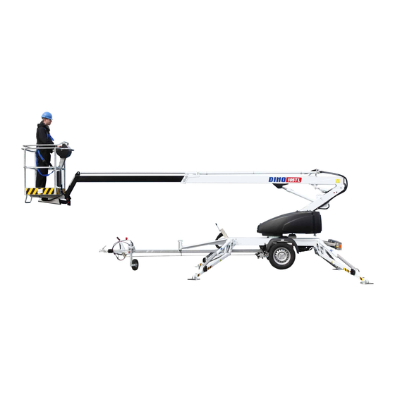
DINO 105TL 4 TECHNICAL SPECIFICATION Max. working height 10.5 m Max. platform height 8.5 m Max. outreach 6.5 m Boom rotation +/- 355° Turn area refer to the reach diagram Support width 3.57 m Transport width 1.5 m Transport length 5.44 m... -
Page 11: General Description Of The Machine
DINO 105TL 4.2 General description of the machine The denominations of the machine’s essential parts and concepts, which are used later in these instructions, are described on this page. drive Platform Telescope cylinder Levelling cylinder of platform, Turning Turning Counter-clockwise (to the... -
Page 12: Escription Of The Machines Intended Use
DINO 105TL 4.3 Description of the machine’s intended use The Access Platform is exclusively intended for transferring people and tools, as well as for acting as a work platform to the limit of its load-bearing capacity and reach (refer to the table of Technical Specifications and Reach Diagram). - Page 13 DINO 105TL USE THE SAFETY HARNESS! Connecting points for the safety harness. Do not use ladders, steps or other similar equipment on the platform. Never throw any objects from the platform. The lift must not be used for transferring goods or persons between different floors or working levels.
- Page 14 DINO 105TL Only skilled persons familiar with servicing and repair instructions are allowed to carry out servicing and repair work. It is strictly prohibited to use a lift which is out of order. The operator must be given instructions and consent from the manufacturer for all such specific work methods or conditions that the manufacturer has not explicitly defined.
-
Page 15: Instructions For Safe Operation
DINO 105TL Instructions for safe operation! Use a safety harness while on the platform. Never load the platform while in the upper position. The lift must not be used when the temperature is below -20°C and the wind speed exceeds 12.5 m/s. -
Page 16: Inspections
DINO 105TL Never use a lift alone. Make sure that there is always someone on the ground, who can call for help in case of an emergency. INSPECTIONS The lift must be subjected to a start-up inspection before it is used for the first time and before starting it up the first time after a major repair or modification work. -
Page 17: Worksite Inspection
DINO 105TL 7 WORKSITE INSPECTION 1. General information Is the lift suited for the intended job? Is the performance of the lift sufficient for the job? (reach, loadability etc.) Is the position of the lift safe? Is the lighting on the worksite sufficient? 2. -
Page 18: Operation Of The Safety Devices
DINO 105TL OPERATION OF THE SAFETY DEVICES 1. Outriggers The safety limit switch RK3 prevents the operation of RK13 the outriggers and the driving device when the RK12 boom does not rest on the transport support. The switch is located on the tow- bar at the transport support. -
Page 19: Operating Controls
DINO 105TL 9 OPERATING CONTROLS 9.1 OPERATING CONTROLS IN THE CHASSIS CONTROL CENTRE Q1.Selector switch S3. High speed selection/start Q1.1 OFF – power off H3.Signal light for the limit switches for outriggers Q1.2 LCB control centre – outriggers S16. Lever for turning the boom system Q1.3 UCB platform control centre... -
Page 20: Operating Controls Of Outriggers
DINO 105TL 9.2 OPERATING CONTROLS OF OUTRIGGERS 1. Rear outrigger, right 2. Rear outrigger, left 3. Front outrigger, left 4. Front outrigger, right 5. Position indicator of chassis (water level) -
Page 21: Operating Controls In The Platform Control Centre Ucb
DINO 105TL OPERATING CONTROLS IN THE PLATFORM CONTROL CENTRE UCB S4. Emergency stop S8. Lever for lifting the boom system S5.Low speed selection/start S9. Lever for telescope movement S6. High speed selection/start S10.Sound signal S7. Lever for turning the boom system S12. -
Page 22: Measures To Be Taken In The Case Of Emergency/If The Lift Is At Risk Of Losing Its Stability
DINO 105TL 10 MEASURES TO BE TAKEN IN THE CASE OF EMERGENCY/IF THE LIFT IS AT RISK OF LOSING ITS STABILITY Reduced stability can be caused by a fault in the lift, the wind or other lateral force, collapse of the standing base or negligence in providing sufficient support. -
Page 23: Starting Up
DINO 105TL 11 STARTING UP 1. Ground stability make sure that the ground is even and hard enough to support the lift in a steady level position. Soil Density Max. material ground pressure kg/cm² Gravel High density Medium density Loose... - Page 24 DINO 105TL 2. Drive the lift to the inspected lifting site apply the parking brake disconnect the lift from the towing vehicle 3. Connection of power supply to the lift connect the mains cable to the power supply for maximum out of the electric motor the voltage must 230 VAC (-10 % +6 %), the...
- Page 25 DINO 105TL 7. Lower the front outriggers 3 and 4 (on the tow-bar side) on the ground 8. Lower the rear outriggers 1 and 2 9. Level the chassis using the outriggers in accordance with the level gauge. DO NOT LOAD THE TOW-BAR JOCKEY WHEEL...
-
Page 26: Driving From The Lcb Centre (Chassis Control Centre)
DINO 105TL 11.1 DRIVING FROM THE LCB CENTRE (CHASSIS CONTROL CENTRE) 10. Turn the selector switch (Q1) to position "LCB control centre" After having levelled the chassis, and brought the outriggers into the support position, you can operate the boom from the control levers S16, S17, S18 and the work platform from the lever S20. -
Page 27: Driving From The Ucb Centre (Platform Control Centre)
DINO 105TL 11.2 DRIVING FROM THE UCB CENTRE (PLATFORM CONTROL CENTRE) 11. Turn the selector switch (Q1) to position UCB (operating from the platform) and take away the key (see point "Operating controls in the chassis control panel LCB"). After having levelled the chassis, and brought all the outriggers correctly into the support position, you can operate the boom from the control levers S7, S8, S9 and the work platform from the lever S12. - Page 28 DINO 105TL 12. Refer to the item “Daily inspections” in the task list for servicing. 13. With the boom slightly lifted and the telescope extended, make sure that the platform does not lower by itself while the operating controls are not being used.
- Page 29 DINO 105TL 18. Adjustment of the platform position From the chassis control panel LCB: Carry out the levelling of the platform while the lift is in the support position (the outriggers on the ground). Adjust the platform position with the boom on a level. No persons allowed on the platform during adjustment.
-
Page 30: Emergency Descent System
DINO 105TL 12 EMERGENCY DESCENT SYSTEM Start by retracting the telescope completely, continue by lowering the boom and finally turn boom system. Operation: 1. Retracting the telescope To retract the telescope, turn the selector lever to the left and pump with the hand pump until the telescope is fully retracted. -
Page 31: Driving Device (Option)
DINO 105TL Shaft for emergency 13 DRIVING DEVICE (option) The hydraulic driving device is intended for moving the lift within the work area if the towing vehicle cannot be used. 1. Do not drive up or down the hill using the driving device if the gradient is greater than 5 per cent, i.e., more than 1/20 (corresponding to a descent of... -
Page 32: Using The Driving Device (Option)
DINO 105TL 13.1 USING THE DRIVING DEVICE (Option) The hydraulic driving device is intended for moving the lift within the work area if the towing vehicle cannot be used. 1. Turn the selector switch (Q1) to position LCB – chassis centre. -
Page 33: Special Instructions For Winter Use
DINO 105TL 14 SPECIAL INSTRUCTIONS FOR WINTER USE – the lowest allowed operating temperature of the lift is -20 °C. – if the temperature is below zero, let the power unit run for a few minutes before starting the movements –... -
Page 34: Connection To The Towing Vehicle
DINO 105TL 4. Close the control centre cover on the work platform. 5. Turn the selector switch Q1 to the position OFF and disconnect the lift from the power supply. 6. Lift the support outriggers. at first the rear support outriggers (do not damage the rear lights) then the front support outriggers (do not damage the jockey wheel) 7. - Page 35 DINO 105TL o that the driving device is disconnected from the wheel...
-
Page 36: Instructions For Service And Maintenance
DINO 105TL INSTRUCTIONS FOR SERVICE AND MAINTENANCE 18 GENERAL SERVICE INSTRUCTIONS – carry out the servicing and inspection of the lift in accordance with the instructions – when it comes to more demanding repair works turn to a specialist or contact the distributor or the manufacturer of the lift –... -
Page 37: Service And Inspection Instructions
DINO 105TL 18.2 SERVICE AND INSPECTION INSTRUCTIONS 1. The first service after 20 hours of operation change the pressure filter element for the hydraulic oil adjust the brakes according to the instructions in point "Wheel brakes and bearings" check the wheel bolts for tightness (90 Nm) after about 100 km of driving 2. -
Page 38: Lubrication Plan
DINO 105TL 18.3 LUBRICATION PLAN... -
Page 39: Long-Term Storage
DINO 105TL EVERY 50 HOURS 1. Bearings of the outrigger cylinders 2. Bearings of the outriggers 3. Bearings of the boom 4. Bearings of the platform 5. Bearings of the levelling cylinders 6. Bearings of the lifting cylinder 7. Sliding surfaces of the telescope 8. -
Page 40: Load Holding And Load Regulation Valves
DINO 105TL 18.5 LOAD HOLDING AND LOAD REGULATION VALVES Check of operation 1. To check the load holding valves of the outrigger cylinders for tightness, measure the height of the chassis from the floor separately at each outrigger, and observe the height in a few minute's time. - Page 41 DINO 105TL...
-
Page 42: Wheel Brakes And Bearings
DINO 105TL 18.6 WHEEL BRAKES AND BEARINGS Adjusting the brakes 1. Raise the lift's wheels off the ground, and support the lift in this position. 2. Make sure that the wheels can rotate freely. 3. The brake rods must be slack (with the handbrake released). -
Page 43: Levelling System Of The Platform
DINO 105TL 18.7 LEVELLING SYSTEM OF THE PLATFORM A so-called slave–master cylinder system is applied for levelling the platform: - The slave cylinder, that is located under the platform, is controlled by a master cylinder. - The platform keeps its level position only if the valves in the system are tight. -
Page 44: Regular Servicing
DINO 105TL 18.8 REGULAR SERVICING The lift shall be serviced regularly at intervals of 11 - 12 month. Under demanding conditions where moist, corrosive substances or corrosive climate may speed up the deterioration of the structure and induce malfunctions, the inspection must be performed more often and the influence of corrosion and malfunctions must be reduced by using appropriate protective means. -
Page 45: Change The Hydraulic Oil And Replace The Filter
DINO 105TL 18.9.2 Change the hydraulic oil and replace the filter (protect your skin against the hydraulic oil) – remove the plug and drain the oil tank with the cylinders of the lift completely retracted (in the transport position) – clean and rinse the oil tank with suitable agent –... -
Page 46: Check The Operation Of The Swing Limiter
DINO 105TL 18.9.4 Check the operation of the swing limiter – check the condition of the hoses and electric wires routed from the turning device to the chassis – check that the hoses and the electric wires are not twisted, while the boom is resting on the support –... -
Page 47: Inspect The Cylinders, And Lubricate The Joint Bearings
DINO 105TL – lubricate the joints (see point "Lubrication plan") 18.9.6 Inspect the cylinders, and lubricate the joint bearings (See point "Lubrication plan") Lower the outriggers into the support position. – from the chassis control centre, drive the lifting cylinder into its upper position, and check the connections for tightness and the condition of the piston rod –... -
Page 48: Check The Overrun
DINO 105TL If you have to turn open or tighten the attachment bolts, do not forget to use bonding adhesive (tighten crosswise) – check the chassis and the welded seams on it; especially around the turning device and attachment points of the outriggers –... -
Page 49: Operation Of The Safety Devices While They Are Controlled From The Chassis Control Panel
DINO 105TL 18.9.11 Operation of the safety devices while they are controlled from the chassis control panel Raise the lift onto the outriggers, and move the platform off the transport position – the outriggers must not operate in any position of the selector switch while the support outriggers are in their upper position –... -
Page 50: Check The Operating Controls On The Platform
DINO 105TL 18.9.13 Check the operating controls on the platform – check the overall condition of the electric appliances inside the box and spray with moisture repellent, if necessary – check the cables – test the sound signal (S10) and the emergency stop (S4)(see point "Operating controls in the platform control panel UCB"). -
Page 51: Test-Run
DINO 105TL 18.9.18 Test-run Perform a test-run with a load of 130 kg following the loading instructions. Check the structures after the test-run. 18.9.19 Draw up an inspection protocol Save your own copy and give an other copy to the customer. -
Page 52: Inspection Instructions
DINO 105TL 19 INSPECTION INSTRUCTIONS All lifting equipment and lifting gear used at a construction site must always be inspected before use. The lifts and related lifting gear used on a work site shall be subjected to a regular maintenance inspection; if possible once a week. (VNA 205/2009, 14§ - 18§) Keep a journal of any notable shortcomings and defects observed and advise the foreman of them. -
Page 53: Sample Of Inspection Protocol For The Access Platform
DINO 105TL 19.1.1 SAMPLE OF INSPECTION PROTOCOL FOR THE ACCESS PLATFORM... - Page 54 DINO 105TL...
-
Page 55: Daily Inspection (Start-Up Inspection)
DINO 105TL 19.2 DAILY INSPECTION (START-UP INSPECTION) To be always performed at a new worksite and in the beginning of every working day. The inspection is performed by the user. In the inspection attention shall be paid to the following issues: –... -
Page 56: Monthly Inspection (Maintenance Inspection)
DINO 105TL 19.3 MONTHLY INSPECTION (MAINTENANCE INSPECTION) The inspection shall be performed by a person who is well familiar with the lift. Task list for the inspection: – perform the measures of the daily inspection – check the attachment points of the boom and the platform –... - Page 57 DINO 105TL This inspection shall be performed by a skilled technician or an expert inspection body with documented evidence of competence according to the requirements presented under point "Inspections" . In the inspection special attention has to be paid to the condition of the steel structures, the safety devices and the operating system.
- Page 58 DINO 105TL load regulation valve of the levelling system • put a load of about 80 kg on the platform • lift and lower the boom 4 - 5 times • make sure that the position of the platform does not change electric directional valves •...
- Page 59 DINO 105TL check the condition of the lifting cylinder bearings and pins and the locking of the pins • check the attachment and condition of the telescope cylinder bearings and pins. • check the condition of the gas springs • check the condition of the master and slave cylinder bearings and pins and the...
-
Page 60: Extraordinary Inspection
DINO 105TL check the condition of the chassis • general condition • check the attachment of the tow-bar to the chassis and the axle • check the condition of the overrun and its attachment to the tow-bar. • check the axle and its attachment to the chassis •... -
Page 61: Test Loading Instructions For Regular Inspection
DINO 105TL 19.6 TEST LOADING INSTRUCTIONS FOR REGULAR INSPECTION 1. Place the lift on an even surface with good carrying capacity. 2. Drive the outriggers to their lowest position (the minimum support width). 3. Turn the boom to the side from the tow-bar and lower it on the ground. -
Page 62: Fault Finding
DINO 105TL FAULT FINDING FAULT REMEDY 1. The electric motor does not start from the start button although the selector switch is in position LCB or UCB Emergency stop button is stuck. Pull up the button and re-start the engine with the start button. - Page 63 DINO 105TL FAULT REMEDY 4. The power supply to the lift is not switched on although the selector switch is in position LCB or UCB Activation of power supply not completed. Press the start button to activate the power supply S2, S3, S5, S6.
- Page 64 DINO 105TL FAULT REMEDY 7. Boom cannot be lifted Refer to item 5. Electric valve open. Remedy as instructed above in conjunction with the seizure of the electric valve spool. The lift turns as the lifting movement is Solenoid valve is stuck in turning position.
- Page 65 DINO 105TL FAULT REMEDY 9. Telescope retracts slowly The load regulation valve leaks. For remedy, refer to item 6 (lock valve). 10. Platform drifts backward Double load regulation valve on the bottom For remedy, refer to item 6 (lock valve).
- Page 66 DINO 105TL FAULT REMEDY 13. Outrigger does not stay in the support position (see illustration) The load regulation valve on the bottom side For remedy, refer to item 6 (lock valve). is leaking. Tightening torque 55 Nm. 14. Outrigger does not stay in the transport position (see illustration) Load regulation valve on the rod side is Measures as above.
- Page 67 DINO 105TL FAULT REMEDY 18. The brakes drag (only one of the wheels brakes) Brake units wrongly adjusted. Readjust the brake units according to instructions. Also refer to point 17 for possible cause. 19. Lift brakes as the engine speed is decreased Shock absorber of the overrun device faulty.
-
Page 68: General Information Of Hydraulics
DINO 105TL 21 GENERAL INFORMATION OF HYDRAULICS The movements require simultaneous operation of two electric valves, i.e.: – change-over valve and telescope cylinder valve – change-over valve and turning of the boom – change-over valve and lifting of the boom –... -
Page 69: Notes
DINO 105TL 21.1 NOTES... -
Page 70: Electric Components 105Tl 10001
DINO 105TL 22 ELECTRIC COMPONENTS 105TL 10001 → 22.1 CHASSIS CONTROL CENTRE (LCB), RELAYS K1: START CONTACTOR (M1) FOR THE ENGINE Control circuit fuse F1 10A K2: AUXILIARY RELAY FOR EMERGENCY STOP SWITCH. Switches off the mains supply (230VAC). Control circuit fuse F1 10A K10: BLOCKING RELAY FOR THE "TELESCOPE OUT"... -
Page 71: Chassis Control Centre (Lcb), Other Items
DINO 105TL S18: TELESCOPE IN-OUT Non-locking lever switch (chassis control panel). S20: PLATFORM LEVELLING FORWARD-BACKWARD Non-locking turn switch (chassis control centre). 22.3 CHASSIS CONTROL CENTRE (LCB), OTHER ITEMS F1: 10 A FUSE FOR START CIRCUIT AND EMEREGENCY DESCENT CIRCUIT F2: 10A FUSE FOR CONTROLLING THE BOOM MOVEMENTS... -
Page 72: Platform Control Centre (Ucb), Other Items
DINO 105TL S10: SOUND SIGNAL SWITCH S12: PLATFORM LEVELLING FORWARD-BACKWARD Control switch, non-locking turn switch. 22.5 PLATFORM CONTROL CENTRE (UCB), OTHER ITEMS PR: SOCKET OUTLET ON THE PLATFORM 230VAC 16A. 22.6 LIMIT SWITCHES RK3: LIMIT SWITCH FOR THE BOOM SUPPORT Prevents the operation of the outriggers and the driving device if the boom does not rest on the support in the transport position. -
Page 73: Electric Diagram 105Tl 10196
DINO 105TL 23 ELECTRIC DIAGRAM 105TL 10196 →... - Page 74 DINO 105TL...
- Page 75 DINO 105TL...
- Page 76 DINO 105TL...
- Page 77 DINO 105TL...
- Page 78 DINO 105TL...
- Page 79 DINO 105TL...
- Page 80 DINO 105TL...
- Page 81 DINO 105TL HYDRAULIC DIAGRAM 10189→...
- Page 82 DINO 105TL 23.1 NOTES...
Need help?
Do you have a question about the DINO 105TL and is the answer not in the manual?
Questions and answers