
Related Manuals for Dinolift DINO 120TB


Summary of Contents for Dinolift DINO 120TB
- Page 1 OPERATING INSTRUCTIONS • 120TB DINO 120T Manufacturer: Dealer: Dinolift Oy Raikkolantie 145 FI-32210 LOIMAA Tel. + 358 20 1772 400 info@dinolift.com www.dinolift.com...
- Page 3 TRANSLATION OF THE ORIGINAL INSTRUCTIONS Valid from serial number 120T 120328, 120330 --> 120TB 60001 -->...
-
Page 4: Table Of Contents
Operating instructions • DINO 120T • 120TB CONTENTS TO THE OPERATOR ....................7 1.1. OVERVIEW OF THE UNIT .................. 8 1.2. INTENDED USE OF THE WORK PLATFORM ........... 8 TECHNICAL SPECIFICATIONS ................. 9 2.1. DIMENSION DRAWING ..................10 2.2. REACH DIAGRAM .................... 11 2.3. - Page 5 5.4. LONG-TERM STORAGE .................. 44 5.5. IN CASE OF EMERGENCY ................46 5.5.1. When at risk of losing the stability ................46 5.5.2. In case of overloading ....................46 5.5.3. In case the power supply is interrupted ............... 46 5.5.4. In case of malfunction, when even the emergency descent system is not operational 47 INSTRUCTIONS FOR FAULT-FINDING ..............
- Page 6 Operating instructions • DINO 120T • 120TB BLAN K...
-
Page 7: To The Operator
Dinolift Oy is constantly developing its products. For this reason, the contents of this manual might not always be in full compliance with the most recent version of the product. Dinolift Oy reserves the right to modify the product without prior notice. Dinolift Oy assumes no liability for any problems caused by changed or missing data or mistakes in this manual. -
Page 8: Overview Of The Unit
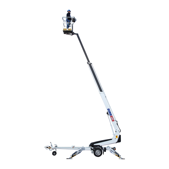
Operating instructions • DINO 120T • 120TB 1.1. OVERVIEW OF THE UNIT This unit is a trailer mounted, towable aerial work platform. It is an aerial work platform, which complies with the EN280 type 1, where travelling is only allowed with the platform in transport configuration. For the operation the lift shall be supported by its hydraulic outriggers, extended so that the wheels of the trailer lift off the ground. -
Page 9: Technical Specifications
TECHNICAL SPECIFICATIONS 120T 120TB Max. working height 12,0 m Max. platform height 10,0 m Max. outreach 7,9 m Boom rotation continuous Platform rotation Turn area refer to the reach diagram Support width 3,15 / 3,55 m Transport width 1,72 m Transport length 5,56 m Transport height... -
Page 10: Dimension Drawing
Operating instructions • DINO 120T • 120TB 2.1. DIMENSION DRAWING... -
Page 11: Reach Diagram
2.2. REACH DIAGRAM... -
Page 12: Example Of The Machine's Nameplate
Operating instructions • DINO 120T • 120TB 2.3. EXAMPLE OF THE MACHINE’S NAMEPLATE The name of the manufacturer, and the production number and serial number of the machine have been marked on the nameplate as shown in the picture below. DINO Type Manufacturer... -
Page 13: Example Of Eu Declaration Of Conformity
In designing the machine, the following harmonised standards have been applied: SFS-EN 280:2013, SFS-EN 60204-1/A1, SFS-EN-ISO 12100 The person, who has compiled the technical construction file: Santtu Siivola Chief Engineer Dinolift Oy, Raikkolantie 145, FI-32210 Loimaa, FINLAND Loimaa 5.2.2016 -----------------------------------------... -
Page 14: Sample Of Inspection Protocol For The Access Platform
Operating instructions • DINO 120T • 120TB 2.5. SAMPLE OF INSPECTION PROTOCOL FOR THE ACCESS PLATFORM TEST CERTIFICATE 28.1.2016 DATE: www.dinolift.com START-UP TESTS: Inspection place: Dinolift Oy Inspector's signature: BASIC KNOWLEDGE Dinolift OY Finland Manufacturer: Place of manufacture: Address: Raikkolantie 145... - Page 15 Raikkolantie 145 FIN-32210 LOIMAA, FINLAND Tel. +358 - 20 - 1772 400, Fax +358 - 2 - 7627 160, e-mail: dino@dinolift.com The initial inspection and test loading of the Dino aerial work platforms is performed by the manufacturer. A protocol, drawn up during the inspection, will accompany the lift.
-
Page 16: Safety
Operating instructions • DINO 120T • 120TB SAFETY All the essential safety instructions and warnings, relevant to transport, use and maintenance of the lift, are described in this chapter. DANGER Failure to observe these instructions and safety regulations may cause a severe injury or WARNING even death. - Page 17 TRANSFERS Observe the maximum allowed gradient when transferring the lift. During transfer in rough terrain, always try to position yourself higher than the machine. Beware of fixed or moving obstacles in the terrain or near the lift while driving. Make sure that you have a clear view of the driving path.
- Page 18 Operating instructions • DINO 120T • 120TB LIFTING AND WORKING ON THE PLATFORM Never exceed the maximum number of persons, maximal loading or lateral force, allowed for the lift. Never add load onto the platform while in the upper position. Before operating, always ensure that the safety devices and the emergency descent system are in working order.
- Page 19 OPERATING CONDITIONS The weather conditions, such as wind, visibility and rain, must always be taken into account so that these will not adversely affect the safe performance of the lifting operations. The use of the lift is prohibited, if the temperature drops under -20 °C or the wind speed exceeds 12.5 m/s Wind speed ( m/s) Conditions on land...
-
Page 20: Safety-Related Notifications
Operating instructions • DINO 120T • 120TB 3.2. SAFETY-RELATED NOTIFICATIONS The following safety alert symbols and safety signal words are used in this manual and in safety labels. Observe all the safety instructions that follow these symbols, in order to avoid dangerous situations and personal injuries. -
Page 21: Safety Devices
3.3. SAFETY DEVICES 1. Supervision of transport position of the boom The safety limit switch RK3 prevents the operation of the outriggers and the driving device when the boom is not resting on the transport support. The switch is located on the tow-bar at the transport support. - Page 22 Operating instructions • DINO 120T • 120TB 4. Supervision of the telescope chain The extension chains for the telescope are doubled. If the load-bearing chain slackens or breaks, the doubling chain prevents the movements of the telescope, and the safety switch RK7 breaks the emergency stop circuit.
- Page 23 6. Safety devices for hose rupture All the load-bearing cylinders are equipped with valves for rupture or leak in the hydraulic system, which prevent the load from falling. Prevent the inching of the Outrigger cylinders Lock valves outriggers in either direction. Prevents the load from falling Lifting cylinder of the boom Load regulation valve...
-
Page 24: Structure And Functions Of The Work Platform
Operating instructions • DINO 120T • 120TB STRUCTURE AND FUNCTIONS OF THE WORK PLATFORM The denominations of the machine’s essential parts and concepts, which are used later in these instructions, are described on the following pages. 4.1. STRUCTURE OF THE WORK PLATFORM 120TB Platform control panel Batteries... -
Page 25: Functions Of The Work Platform
4.2. FUNCTIONS OF THE WORK PLATFORM Turn counter- clockwise Left Drive direction Right Turn clockwise Levelling the platform Lifting/lowering the boom Turning the boom... -
Page 26: Operating Controls For The Functions
Operating instructions • DINO 120T • 120TB 4.3. OPERATING CONTROLS FOR THE FUNCTIONS 4.3.1. 120T Operating controls in the chassis control centre Selector switch Speed selector switch and activation switch for the movements (is used Ignition off Kpl/kone VILAKONE OY simultaneously with the control levers for Operating controls in the chassis Piirustuksen numero... -
Page 27: 120Tb Operating Controls In The Chassis Control Centre
4.3.2. 120TB Operating controls in the chassis control centre Selector switch Speed selector switch and activation switch for the movements (is used Ignition off Kpl/kone VILAKONE OY simultaneously with the control levers for Operating controls in the chassis Piirustuksen numero Revisio Ohjetarra, joystick 41603606... -
Page 28: Operating Controls For The Outriggers
Operating instructions • DINO 120T • 120TB 4.3.3. Operating controls for the outriggers Rear outrigger, right Rear outrigger, left Front outrigger, left Front outrigger, right Position indicator of chassis 120TB Start button for outrigger operation... -
Page 29: Operating Controls In The Platform Control Centre
4.3.4. Operating controls in the platform control centre Close the cover of the chassis control centre before operating the controls on the platform. The cover must not be locked while the lift is in operation. Emergency stop Speed selector switch and activation switch for the movements (is used Sound signal button simultaneously with the control levers for... -
Page 30: Operating Instructions
DANGER Operating instructions • DINO 120T • 120TB WARNING OPERATING INSTRUCTIONS CAUTION 5.1. START-UP NOTICE Before operating the lift, perform all daily maintenance measures listed in the maintenance schedule. The operator must do a worksite inspection and daily maintenance: • at the beginning of each workday •... -
Page 31: Positioning The Lift
5.1.2. Positioning the lift 1. make sure that the ground is even and hard enough to support the lift in a steady, level position. Max. ground pressure Soil material Density kg/cm² (N/cm²) Gravel High density 6 (59) Medium density 4 (39) Loose 2 (20) Sand... -
Page 32: Starting Up
Operating instructions • DINO 120T • 120TB 5.1.3. Starting up POWERED BY AC-SUPPLY 120T While the mains voltage is plugged in, the operating voltage of 12 VDC is supplied by a power source. • connect the mains cable to the power supply •... - Page 33 POWERED BY POWER PACK (OPTIONAL IN 120T) Starting the power pack: 1. Open the engine's petrol cock HA. 2. Activate the key switch in the chassis control centre of the lift. DANGER 3. Depress the choke button S40 in the electric centre of the power pack, and start the engine by turning the start switch S6.
-
Page 34: Supporting The Lift
Operating instructions • DINO 120T • 120TB 5.1.4. Supporting the lift 1. Lower the front support outriggers (on the tow-bar side). 2. Lower the support outriggers in the rear. (do not damage the tow-bar jockey wheel). 3. Level the chassis with the outriggers with the help of the level gauge (16). The air bubble must be located inside the inner ring. -
Page 35: Operation
DANGER 5.2. OPERATION WARNING Carry out all the daily maintenance routines and inspections in accordance with the CAUTION maintenance instructions before operating the lift. Failure to check the safety devices may cause a serious injury or make the consequences of an accident worse. NOTICE 5.2.1. -
Page 36: Operating The Lift From The Platform Control Centre
Operating instructions • DINO 120T • 120TB 5.2.2. Operating the lift from the platform control centre Kpl/kone VILAKONE OY 1. Turn the selector switch to the position ”Platform control centre Piirustuksen numero Revisio UCB”, and remove the key. Do not lock the protective cover for the Ohjetarra, joystick 41603606 chassis control centre. - Page 37 Working a long time in the same position • There are pushbuttons for both stopping and starting the engine on the chassis control panel. When the weather is warm, and the platform is kept for a longer period in the same position, it is not necessary to let the engine run continuously.
-
Page 38: Special Instructions For Winter Use
Operating instructions • DINO 120T • 120TB 5.2.3. Special instructions for winter use The lowest allowed operating temperature of the lift is -20 °C In cold conditions, carry out the following special actions in addition to the normal start-up procedure: 1. -
Page 39: Transferring The Lift
5.3. TRANSFERRING THE LIFT The lift can be transfered by towing or using its own driving device. The lift may only be moved in the transport position. No persons or load are allowed on the platform during the transportation. 5.3.1. Preparing the lift for transport During transfer, the lift must always be in the transport position. -
Page 40: Using The Driving Device
Operating instructions • DINO 120T • 120TB 5.3.2. Using the driving device The hydraulic driving device is intended for moving the lift within the work area if the towing vehicle cannot be used. During transfer in rough terrain, always try to position yourself higher than the machine. - Page 41 WARNING CAUTION NOTICE Be careful not to damage the jockey wheel tube by extending it too much. When moving the lift using the driving device, a suitable length for the jockey wheel's stem can be achieved by adjusting the gap between the lower surface of the tow-bar/brake rod and the wheel to 1-3 cm.
-
Page 42: Towing The Lift
Operating instructions • DINO 120T • 120TB 5.3.3. Towing the lift Connecting to the towing vehicle 1. Lift up and push forward (in the driving direction) the handle of the ball-coupling. Now the ball-coupling is released. 2. Press the ball-coupling onto the towball using only a little force. The connection and locking take place automatically. -
Page 43: Lifting The Device
5.3.4. Lifting the device The device can be lifted using the lugs shown in the picture. The lifting lugs are located symmetrically on both sides of the lift. During lifting the aerial work platform must be in the transport position. Remove all loose material from the top of the frame structures and the work platform before lifting. -
Page 44: Long-Term Storage
DANGER Operating instructions • DINO 120T • 120TB WARNING 5.4. LONG-TERM STORAGE Clean the machine carefully, lubricate it and apply protective grease to it before putting it into storage for a longer period of time (see point “Lubrication plan”). Repeat the cleaning and CAUTION lubrication procedures when you resume the operation. - Page 45 B LAN K...
-
Page 46: In Case Of Emergency
Operating instructions • DINO 120T • 120TB 5.5. IN CASE OF EMERGENCY 5.5.1. When at risk of losing the stability Reduced stability can be caused by a fault in the lift, the wind or other lateral force, collapse of the standing base or negligence in providing sufficient support. In most cases one sign of reduced stability is the inclination of the lift. -
Page 47: In Case Of Malfunction, When Even The Emergency Descent System Is Not Operational
The emergency descent system can only be operated from the ground. If you are on the platform, call for help to operate the system. Operation: 1. Retracting the telescope Open the emergency descent valve for the telescope by turning the screw 27 clockwise and retract the telescope completely by pumping with the hand pump 28. -
Page 48: Instructions For Fault-Finding
Operating instructions • DINO 120T • 120TB INSTRUCTIONS FOR FAULT-FINDING 120T START FAULT REMEDY 1. The electric motor does not start from its start button although the selector switch 1 is in the position that enables operation from either the chassis or the platform control centre The emergency stop button has jammed in the Pull up the button and re-start the motor from the... - Page 49 FAULT REMEDY 3. None of the boom movements is operational, although the electric motor is running and the selector switch stands in the correct position (operation either from the chassis control centre or the platform control centre) Make sure that the outriggers are steady Green signal light for outriggers is not supported on the ground, and the tyres are off the illuminated.
- Page 50 Operating instructions • DINO 120T • 120TB NOTES...
- Page 51 NOTES...
-
Page 52: Maintenance Schedule
Operating instructions • DINO 120T • 120TB MAINTENANCE SCHEDULE Maint. Schedule Person responsible Reference Operating Daily Operator instructions 1 month / 100 Maintenance Competent person who is familiar with the lift hours* instructions DANGER 6 months / 400 Maintenance Competent person who is familiar with the lift hours* instructions Annually / 800... - Page 53 Maintenance measures 20 Driving device 21 Lights 22 Hydraulic oil 23 Hydraulic hoses, pipes and fittings Condition and attachment of battery, electrical devices and wiring 25 Hydraulic pressure 26 Condition of safety limit switches 27 Operation of safety limit switches 28 Load holding and load regulation valves 29 Platform levelling system 30 Platform control devices...
-
Page 54: Schedule For Inspections Required By The Authorities
Operating instructions • DINO 120T • 120TB 7.1. SCHEDULE FOR INSPECTIONS REQUIRED BY THE AUTHORITIES Inspections must be performed in accordance with local, state or federal regulations, legislation, directives, standards. The manufacturer recommends following inspections, as required by local authorities in platforms country of origin. A pre-use inspection must be done before taking the platform to use for the first time and before first start-up after major repairs and alterations. -
Page 55: Lubrication Plan
7.2. LUBRICATION PLAN... -
Page 56: Routine Maintenance During Operation
Operating instructions • DINO 120T • 120TB ROUTINE MAINTENANCE DURING OPERATION The maintenance operations, that are the responsibility of the operator, are described in this chapter. The more demanding maintenance operations that require special skills, special tools or specific measurements and adjustment values are instructed in the separate Maintenance Instructions. -
Page 57: Instructions For Daily Maintenance And Inspections
8.1. INSTRUCTIONS FOR DAILY MAINTENANCE AND INSPECTIONS 8.1.1. Check the condition of chassis, the boom and the work platform Check visually the condition of the access routes, the work platform, the platform gate and the handrails. Check visually the condition of the boom and the frame structures. 8.1.2. -
Page 58: Check The Operation Of The Safety Limit Switches
Operating instructions • DINO 120T • 120TB 8.1.6. Check the operation of the safety limit switches Test the operation of the safety limit switches that prevent the movements of the boom and the outriggers as follows: 1. The lift is in the transport position with the outriggers in the upper position, and the driving device connected. -
Page 59: Maintenance Of The Batteries
DANGER WARNING 8.2. MAINTENANCE OF THE BATTERIES CAUTION Electrolytic liquid is highly corrosive – always wear protective clothing and eye guards. NOTICE The batteries generate hydrogen gas during charging – naked flame prohibited, danger of explosion DANGER Always keep the batteries well charged •... - Page 60 DANGER Operating instructions • DINO 120T • 120TB WARNING Test the condition of the batteries regularly • Specific weight of the liquid CAUTION 1.277 Battery 100 % charged NOTICE If maintained well, the batteries will last 4-5 years of normal operation. Incorrect use shortens their service life rapidly.
- Page 61 B L A N K...
- Page 62 Operating instructions • DINO 120T • 120TB BLANK...
-
Page 63: Change Of Owner
If you have purchased a used DINO lift from some other than the manufacturer, please post your details to the manufacturer using the form on this page, and send it to: info@dinolift.com This information makes it possible for us to provide you with the safety bulletins and other campaigns relevant to your machine. - Page 64 Operating instructions • DINO 120T • 120TB NOTES...
- Page 65 NOTES...
Need help?
Do you have a question about the DINO 120TB and is the answer not in the manual?
Questions and answers