Dinolift DINO 160XT II Operating Instructions Manual
Hide thumbs
Also See for DINO 160XT II:
- Maintenance instructions manual (82 pages) ,
- Operating instructions manual (65 pages) ,
- Quick manual (2 pages)

Subscribe to Our Youtube Channel
Related Manuals for Dinolift DINO 160XT II


Summary of Contents for Dinolift DINO 160XT II
- Page 1 OPERATING INSTRUCTIONS DINO 160XT II • 180XT II • 210XT II Manufacturer: Dealer: Dinolift Oy Raikkolantie 145 FI-32210 LOIMAA Tel. + 358 20 1772 400 info@dinolift.com www.dinolift.com...
- Page 3 TRANSLATION OF THE ORIGINAL INSTRUCTIONS Valid from serial number 160XT II 17280 - 180XT II 30135 - 210XT II 3484 -...
-
Page 4: Table Of Contents
Operating instructions • DINO 160XT II • 180XT II • 210XT II CONTENTS TO THE OPERATOR ....................7 1.1. OVERVIEW OF THE UNIT .................. 8 1.2. INTENDED USE OF THE WORK PLATFORM ........... 8 TECHNICAL SPECIFICATIONS ................. 9 2.1. DIMENSION DRAWINGS ................. 11 2.1.1. - Page 5 5.1.5. Levelling the lift ......................45 5.2. INSTRUCTIONS FOR WORKING ..............47 5.2.1. Operating the lift from the chassis control centre LCB ..........47 5.2.2. Operating the lift from the platform control centre UCB ..........47 5.2.3. Special instructions for winter use ................50 5.2.4.
- Page 6 Operating instructions • DINO 160XT II • 180XT II • 210XT II BLANK...
-
Page 7: To The Operator
Dinolift Oy is constantly developing its products. For this reason, the contents of this manual might not always be in full compliance with the most recent version of the product. Dinolift Oy reserves the right to modify the product without prior notice. Dinolift Oy assumes no liability for any problems caused by changed or missing data or mistakes in this manual. -
Page 8: Overview Of The Unit
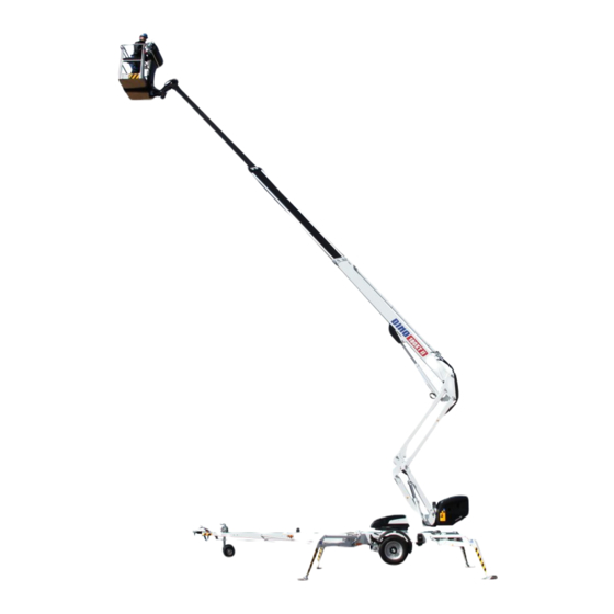
Operating instructions • DINO 160XT II • 180XT II • 210XT II 1.1. OVERVIEW OF THE UNIT This unit is a trailer mounted, towable aerial work platform. It is an aerial work platform, which complies with the EN280 type 1, where travelling is only allowed with the platform in transport configuration. -
Page 9: Technical Specifications
TECHNICAL SPECIFICATIONS 160XT II 180XT II 210XT II Max. working height 16,0 m 18,0 m 21,0 m Max. platform height 14,0 m 16,0 m 19,0 m Max. outreach 9,1 m 11,2 m 11,7 m Boom rotation continuous Platform rotation 180° Turn area refer to the reach diagram Support width... - Page 10 Operating instructions • DINO 160XT II • 180XT II • 210XT II Optional engines Hatz 1B30 EPA / CARB Tier 4 Final Fuel Diesel Net power 4,4 kW (6 hv) / 2800 r/min Oil tank volume 1,1 l Sound pressure level...
-
Page 11: Dimension Drawings
2.1. DIMENSION DRAWINGS 2.1.1. 160 XT II... -
Page 12: 180 Xt Ii
Operating instructions • DINO 160XT II • 180XT II • 210XT II 2.1.2. 180 XT II... -
Page 13: 210 Xt Ii
2.1.3. 210 XT II... -
Page 14: Reach Diagram
Operating instructions • DINO 160XT II • 180XT II • 210XT II 2.2. REACH DIAGRAM 2.2.1. 160 XT II 215 KG 475 LB DINO 160XT II... -
Page 15: 180 Xt Ii
2.2.2. 180 XT II... -
Page 16: 210 Xt Ii
Operating instructions • DINO 160XT II • 180XT II • 210XT II 2.2.3. 210 XT II 215 KG 475 LB 120 KG 265 LB 80 KG 175 LB... -
Page 17: Example Of The Machine's Nameplate
2.3. EXAMPLE OF THE MACHINE’S NAMEPLATE The name of the manufacturer, and the production number and serial number of the machine have been marked on the nameplate as shown in the picture below. DINO Type Manufacturer Raikkolantie 145 Year of manufacture Address of manufacture 32210 Loimaa FINLAND... -
Page 18: Example Of Eu Declaration Of Conformity
Operating instructions • DINO 160XT II • 180XT II • 210XT II 2.4. EXAMPLE OF EU DECLARATION OF CONFORMITY EU declaration of conformity for machine Manufacturer Dinolift Oy Raikkolantie 145 FI-32210 Loimaa, FINLAND declares that DINO 180XT II Aerial Work Platform, no. YGCD180XTE2030011... -
Page 19: Sample Of Inspection Protocol For The Access Platform
2.5. SAMPLE OF INSPECTION PROTOCOL FOR THE ACCESS PLATFORM TEST CERTIFICATE DATE: 16.9.2014 www.dinolift.com START-UP TESTS: Inspection place: Dinolift Oy Inspector's signature: 1074 BASIC KNOWLEDGE Manufacturer: Dinolift OY Place of manufacture: Finland Raikkolantie 145 Address: 32210 LOIMAA Importer: Type of lift:... - Page 20 Raikkolantie 145 FIN-32210 LOIMAA, FINLAND Tel. +358 - 20 - 1772 400, Fax +358 - 2 - 7627 160, e-mail: info@dinolift.com The initial inspection and test loading of the Dino aerial work platforms is performed by the manufacturer. A protocol, drawn up during the inspection, will accompany the lift.
-
Page 21: Safety
SAFETY All the essential safety instructions and warnings, relevant to transport, use and maintenance of the lift, are described in this chapter. DANGER Failure to observe these instructions and safety regulations may cause a severe injury or even death. Familiarise yourself with all the safety regulations, operating instructions and signs affixed to the machine, and follow them. - Page 22 Operating instructions • DINO 160XT II • 180XT II • 210XT II TRANSFERS Observe the maximum allowed gradient when transferring the lift. During transfer in rough terrain, always try to position yourself higher than the machine. Beware of fixed or moving obstacles in the terrain or near the lift while driving. Make sure that you have a clear view of the driving path.
- Page 23 LIFTING AND WORKING ON THE PLATFORM Never exceed the maximum number of persons, maximal loading or lateral force, allowed for the lift. Never add load onto the platform while in the upper position. Before operating, always ensure that the safety devices and the emergency descent system are in working order.
- Page 24 Operating instructions • DINO 160XT II • 180XT II • 210XT II OPERATING CONDITIONS The weather conditions, such as wind, visibility and rain, must always be taken into account so that these will not adversely affect the safe performance of the lifting operations.
-
Page 25: Safety-Related Notifications
3.2. SAFETY-RELATED NOTIFICATIONS The following safety alert symbols and safety signal words are used in this manual. Observe all the safety instructions that follow these symbols, in order to avoid dangerous situations and personal injuries. This is a general safety alert symbol and it is used to alert you about a potential hazard. - Page 26 Operating instructions • DINO 160XT II • 180XT II • 210XT II Crush hazard - moving Crush hazard - moving Crush hazard - falling Harmful exhaust parts parts objects emissions Wind speed Tip over hazard Fall hazard Support load No smoking...
-
Page 27: Safety Labels
3.3. SAFETY LABELS (ANSI/CSA/AS/NZS) The following safety labels must be intact, clean and legible. Replace the labels if necessary. CE Safety labels and all instructional labels are listed in the spare parts list. 160XT: 54.1075 180XT: 54.1371 210XT: 54.1083 AS/NZ US/CAN 54.1660... - Page 28 Operating instructions • DINO 160XT II • 180XT II • 210XT II 160XT II: 54.1075 180XT II: 54.1371 210XT II: 54.1083 160-180XT: 54.1610 CAUTION 210XT: 54.1603...
- Page 29 160-180XT: 54.1610 210XT: 54.1603 160-180XTB II: 54.1610 210XTB II: 54.1603...
-
Page 30: Safety Devices
Operating instructions • DINO 160XT II • 180XT II • 210XT II 3.4. SAFETY DEVICES 1. Supervision of transport position of the boom The safety limit switch RK3 prevents the operation of the outriggers and the driving device when the boom is not resting on the transport support. The switch is located on the tow-bar at the transport support. - Page 31 The green light in the control centre on the platform is lit, when the platform is within the allowed operating range. The reach are limit switch RK4 stops the movements that impair the stability of the lift (extending the telescope and lowering the boom) at a predetermined position. Adjusted values of the limits: 100 mm RK4 - L...
- Page 32 Operating instructions • DINO 160XT II • 180XT II • 210XT II 5. Supervision of the telescope chain The extension chains for the telescope are doubled. If the load-bearing chain slackens or breaks, the doubling chain prevents the movements of the telescope, and the safety switch RK7/RK8 breaks the emergency stop circuit.
- Page 33 7. Safety devices for hose rupture All the load-bearing cylinders are equipped with valves for rupture or leak in the hydraulic system, which prevent the load from falling. Prevent the inching of the Outrigger cylinders Lock valves outriggers in either direction. Lifting cylinder of the boom Load regulation valve Prevents the load from falling...
-
Page 34: Basic Structure And Functions
Operating instructions • DINO 160XT II • 180XT II • 210XT II BASIC STRUCTURE AND FUNCTIONS The denominations of the machine’s essential parts and concepts, which are used later in these instructions, are described on this page. Platform control centre UCB 4.1. -
Page 35: Basic Functions
4.2. BASIC FUNCTIONS Swing counter- clockwise Left Drive direction Right Swing clockwise Platform levelling Boom lift / lowering Articulated arms lifting / lowering Platform Boom rotation turning... -
Page 36: Operating Controls
Operating instructions • DINO 160XT II • 180XT II • 210XT II 4.3. OPERATING CONTROLS 4.3.1. Operating controls in chassis control centre LCB Selector switch Lever switch for turning OFF-power off Q1.1 Lever switch for boom system LCB-control centre – outriggers – hydraulic Q1.2... -
Page 37: Operating Controls Of Drive System
4.3.2. Operating controls of drive system 28A. Forward - backward 28A + 28L drive to the left 28A + 28R drive to the right 4.3.3. Operating controls of outriggers Front outrigger, right Front outrigger, left Rear outrigger, left Rear outrigger, right Position indicator of chassis... -
Page 38: Operating Controls In Platform Control Centre Ucb
Operating instructions • DINO 160XT II • 180XT II • 210XT II 4.3.4. Operating controls in platform control centre UCB Close the cover of the chassis control centre before operating the controls on the platform. The cover must not be locked while the lift is in operation. - Page 39 17. Control lever The functions to be controlled are selected using the ”dead-man-buttons” at the end of the joystick. Always press the button first, and only after that, turn the handle. The safety connection prevents the movements, if the handle is turned before depressing the button. Boom up Boom to the left Boom to the right...
-
Page 40: Setup With Two Control Levers (Option)
Operating instructions • DINO 160XT II • 180XT II • 210XT II 4.3.5. Setup with two control levers (option) Platform contol centre UCB can be fitted with two control levers as an option. Right and left control lever (17 right/left) replace the normal control lever (17). Different functions are selected by turning the joystick in the desired direction of movement. -
Page 41: Automatic Levelling And Electric Control Of Driving Device - Dcb Centre (Option)
AUTOMATIC LEVELLING AND ELECTRIC CONTROL OF DRIVING DEVICE – DCB 4.4. CENTRE (OPTION) 45-48 Lever switch for driving, right (to the Lever switch for automatic levelling front-rear) Lever switch for driving, left (to the front-rear) 50 Emergency stop Depressing the driving device rollers (option) 51 Light for automatic levelling 45-48 Lever switches for outriggers 1-4... -
Page 42: Operating Instructions
Operating instructions • DINO 160XT II • 180XT II • 210XT II OPERATING INSTRUCTIONS 5.1. START-UP NOTICE Before operating the lift, perform all daily maintenance measures listed in the maintenance schedule. The operator must do a worksite inspection and daily maintenance: •... -
Page 43: Positioning The Lift
5.1.2. Positioning the lift 1. make sure that the ground is even and hard enough to support the lift in a steady, level position. Max. ground pressure Soil material Density kg/cm² (N/cm²) Gravel High density 6 (59) Medium density 4 (39) Loose 2 (20) Sand... -
Page 44: Connecting The Power Supply To The Lift
Operating instructions • DINO 160XT II • 180XT II • 210XT II 5.1.3. Connecting the power supply to the lift A. POWERED BY AC-SUPPLY While the mains voltage is plugged in, the operating voltage of 12 VDC is supplied by a power source. -
Page 45: Starting Up
5.1.4. Starting up 1. Turn the selector switch (1) to position ”LCB centre”. 2. Start the engine with start -button The electric timer of the lift automatically disconnects the supply voltage (12 VDC) in about 1 hour after the electric motor or the combustion engine has been turned off. Re-activate the power supply by pressing the start button either in the chassis control centre or in the platform control centre. - Page 46 Operating instructions • DINO 160XT II • 180XT II • 210XT II Before using the lift, check that: • the cassis is level • the wheels are clearly off the ground all outriggers are firmly supported on the ground •...
-
Page 47: Instructions For Working
5.2. INSTRUCTIONS FOR WORKING WARNING Do all daily maintenance tasks and operational inspections stated in the maintenance manual before operating the lift. Failure to check the correct functioning of safety devices may cause serious injury or make the consequences of an accident worse. All malfunctions in safety devices must be repaired before operating the lift 5.2.1. - Page 48 Operating instructions • DINO 160XT II • 180XT II • 210XT II To operate the movements of the boom system, press first the • rocker switch 17 at the end of the control lever, and after that, move the control lever carefully in the desired direction of movement of the boom.
- Page 49 The platform movements can be operated with continually adjustable speed from the platform control centre (not from the chassis control centre). Only one movement can be operated at a time. If several control levers are operated simultaneously, only the movement with the least resistance will operate.
-
Page 50: Special Instructions For Winter Use
Operating instructions • DINO 160XT II • 180XT II • 210XT II When leaving the lift • drive the lift to a safe position, preferably to the transport position • switch off the power unit • prevent unauthorized use of the lift by locking the control centre cover 5.2.3. -
Page 51: Transport
5.3. TRANSPORT The lift can be moved by towing or with the platforms driving device. Moving the lift is only allowed in the transport position. No persons or other additional load is allowed on the platform while transport. 5.3.1. Preparing the lift for transport The lift must be in transport position. -
Page 52: Driving With The Driving Device
Operating instructions • DINO 160XT II • 180XT II • 210XT II 5.3.2. Driving with the driving device The hydraulic driving device is intended for moving the lift within the work area if the towing vehicle cannot be used. During transfer in rough terrain, try to stay above the machine . -
Page 53: Towing The Lift
When driving on a slope: 1. When driving on a slope, the tow-bar must always point towards the descent. Never drive with the driving device with the tow-bar pointing towards the ascent. 2. Place chocks under the wheels before disconnecting the device from the towing vehicle. 3. - Page 54 Operating instructions • DINO 160XT II • 180XT II • 210XT II 3. Connect the emergency stop wires and light plug to the vehicle. Check the cable for chafing and proper operation of the wires. 4. Check the operation of the lights.
-
Page 55: Lifting The Device
5.4. LIFTING THE DEVICE The device can be lifted from the lugs shown in the picture. Lugs are placed symmetrically on both sides. Lifting lugs are also marked in the machine with instructional labels. During lifting the platform must be in transport position. Remove all loose material and other excess load from the platform before lifting. -
Page 56: In Case Of Emergency
Operating instructions • DINO 160XT II • 180XT II • 210XT II 5.6. IN CASE OF EMERGENCY 5.6.1. When at risk of losing the stability Reduced stability can be caused by a fault in the lift, the wind or other lateral force, collapse of the standing base or negligence in providing sufficient support. -
Page 57: In Case Of Malfunction, When Even The Emergency Descent System Is Not Operational
Note! The emergency descent system can also be used for raising the support outriggers to the transport position Always check the condition of the battery for the emergency descent system before putting the lift into operation. (See point “Operation of the safety devices”) Setup of the emergency descent system •... -
Page 58: Instructions For Fault-Finding
Operating instructions • DINO 160XT II • 180XT II • 210XT II INSTRUCTIONS FOR FAULT-FINDING FAULT REMEDY 1. The electric motor does not start from its start button although the selector switch 1 is in the position that enables operation from either the chassis or the platform control... - Page 59 FAULT REMEDY 7. Outriggers do not move The boom is not resting on the transport support. Drive the boom onto the transport support. The selector switch is in the wrong position. Turn the selector switch to the correct position. Limit switch on the boom support has not closed. Drive the boom onto the transport support. 8.
- Page 60 Operating instructions • DINO 160XT II • 180XT II • 210XT II NOTES...
- Page 61 NOTES...
-
Page 62: Servicing And Maintenance
Operating instructions • DINO 160XT II • 180XT II • 210XT II SERVICING AND MAINTENANCE Maint. Schedule Person responsible Reference Operating Daily Operator instructions 1 month / 100 Maintenance Competent person who is familiar with the lift hours* instructions 6 months / 400... - Page 63 Maintenance item Axles and suspension Driving device Lights Hydraulic oil Hydraulic hoses, pipes and fittings Condition and attachment of battery, electrical devices and wiring Hydraulic pressure Condition of safety limit switches Operation of safety limit switches Operation of overload protection device Load holding and load regulation valves Platform levelling system Platform control devices...
-
Page 64: Inspections Required By Authorities
Operating instructions • DINO 160XT II • 180XT II • 210XT II 7.1. INSPECTIONS REQUIRED BY AUTHORITIES Inspections must be performed in accordance with local, state or federal regulations, legislation, directives, standards. The manufacturer recommends following inspections, as required by local authorities in platforms country of origin. -
Page 65: Lubrication Plan
7.2. LUBRICATION PLAN... -
Page 66: Routine Maintenance During Operation
Operating instructions • DINO 160XT II • 180XT II • 210XT II ROUTINE MAINTENANCE DURING OPERATION This chapter describes the service and maintenance operations that the operator of the platform is responsible for. Other maintenance operations require special training, tools and materials or specific measurements and adjustment values. -
Page 67: Daily Maintenance Tasks
8.1. DAILY MAINTENANCE TASKS 8.1.1. Condition of chassis, boom and work platform Inspect visually the condition of access systems, work platform, platform gate and handrails. Check that the chassis and boom have no visible signs of structural damage. 8.1.2. Check the tyres and tyre pressure Inspect the condition of tyres visually and chack that they are not flat. -
Page 68: Check The Emergency Descent, Emergency Stop And Sound Signal
Operating instructions • DINO 160XT II • 180XT II • 210XT II 8.1.7. Check the emergency descent, emergency stop and sound signal Test the correct operation of emergency stop, emergency descent system and the sound signal from the lower controls and platform controls. - Page 69 B L A N K...
- Page 70 Operating instructions • DINO 160XT II • 180XT II • 210XT II BLANK...
-
Page 71: Change Of Owner
If you have purchased a used DINO lift from some other than the manufacturer, please post your details to the manufacturer using the form on this page, and send it to: info@dinolift.com This information makes it possible for us to provide you with the safety bulletins and other campaigns relevant to your machine. - Page 72 Operating instructions • DINO 160XT II • 180XT II • 210XT II NOTES...
- Page 73 NOTES...
Need help?
Do you have a question about the DINO 160XT II and is the answer not in the manual?
Questions and answers