
Related Manuals for Dinolift DINO 105T


Summary of Contents for Dinolift DINO 105T
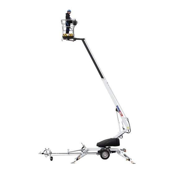
- Page 1 DINO ® OPERATING INSTRUCTIONS ® Raikkolantie 145 FI-32210 LOIMAA T. +358 2 762 5900 F. +358 2 762 7160 dino@dinolift.com www.dinolift.com...
- Page 2 DINO 105T...
- Page 3 DINO 105T OPERATING INSTRUCTIONS...
- Page 4 DINO 105T 5336 Valid from serial number...
-
Page 5: Table Of Contents
DINO 105T CONTENTS TECHNICAL SPECIFICATION ............................7 REACH DIAGRAM................................8 GENERAL SAFETY REGULATIONS ..........................9 REGULAR INSPECTION ..............................11 WORKSITE INSPECTION ..............................12 OPERATION OF THE SAFETY DEVICES........................13 (OK1) NSURE THE OPERATION OF THE SAFETY DEVICES DO NOT LOCK THE CHASSIS PANEL COVER WITH KEY WHILE THE . - Page 6 DINO 105T MAIN CONTROL CENTRE (LCB), OTHER ITEMS.......................63 MAIN CONTROL CENTRE (LCB), SWITCHES......................63 CONTROL CENTRE (UCB), RELAYS ..........................64 CONTROL CENTRE (UCB), SWITCHES........................64 CONTROL CENTRE (OCB), CONTROL OF OUTRIGGERS ..................64 CONTROL CENTRE (PLCB) QUICKSILVER SWITCHES FOR LEVELLING OF THE PLATFORM......64 VALVES, CHASSIS ................................65 VALVES, TURNING DEVICE ............................65...
-
Page 7: Technical Specification
DINO 105T TECHNICAL SPECIFICATION Max. working height 10.5 m Max. platform height 8.5 m Max. outreach to the side 6.0 m Boom rotation continuous Support width 3.20 m Transport width, max 1.48 m Transport width, min 0.78 m Transport length 5.57 m... -
Page 8: Reach Diagram
DINO 105T REACH DIAGRAM 120 kg... -
Page 9: General Safety Regulations
DINO 105T GENERAL SAFETY REGULATIONS Make yourself familiar with these operating instructions before using the lift! Keep these Operating Instructions in the place reserved for them. Make sure that all users of the lift are familiar with these instructions. Advice the new users and strictly follow all instructions given by the manufacturer. - Page 10 DINO 105T Do not use ladders, steps or other similar equipment on the platform. Never throw any objects from the platform. The lift must not be used for transferring goods or persons between different floors or working levels. Never disable the operation of any safety device.
-
Page 11: Regular Inspection
DINO 105T REGULAR INSPECTION A thorough inspection of the lift must be carried out at least once every twelve (12) months. The inspection should only be carried out by a person who is technically trained and familiar with the function, use and construction of the lift. -
Page 12: Worksite Inspection
DINO 105T WORKSITE INSPECTION 1. General Is the lift suited for the intended job? Is the performance of the lift sufficient for the job? (reach, loadability etc.) Is the position of the lift safe? Is the lighting on the worksiite sufficient? 2. -
Page 13: Operation Of The Safety Devices
DINO 105T OPERATION OF THE SAFETY DEVICES RK4-RK7 RK11-RK14 1. Limit switch on the boom support RK3 The safety limit switch prevents the operation of the outriggers if the boom does not rest on the transport support. The switch is located on the parking support of the towbar. -
Page 14: Operating Controls
DINO 105T OPERATING CONTROLS OPERATING CONTROLS ON CHASSIS PANEL Selector switch 0 - ignition off 1 -outrigger circuit 2 -controlling the boom from the platform 3 -controlling the boom from the chassis 2. Start button 3. Emergency stop button 4. Signal light for limit switches on the axle 5. -
Page 15: Control Of The Outriggers And The Water Level
DINO 105T CONTROL OF THE OUTRIGGERS AND THE WATER LEVEL Rear outrigger, right. 2. Rear outrigger, left 3. Front outrigger, left 4. Front outrigger, right. A = Raising of the outrigger B = Lowering of the outrigger Level the chassis with the outriggers with the help of the level position indicator (Water level). -
Page 16: Operating Controls On The Platform
DINO 105T OPERATING CONTROLS ON THE PLATFORM Lock the operating switch in position 2 (controlling the boom with the platform panel) Close the chassis control panel cover before operating the controls on the platform. The cover must not be locked while the lift is in operation. -
Page 17: Measures To Be Taken If The Lift Is At Risk Of Losing Its Stability
DINO 105T MEASURES TO BE TAKEN IF THE LIFT IS AT RISK OF LOSING ITS STABILITY The reason for the reduced stability can be a fault in the lift, the wind or other lateral force, collapse of the standing base or negligence in providing sufficient support. In most cases a sign of the reduced stability is the inclination of the lift. -
Page 18: Start-Up
DINO 105T START-UP 1. Ground stability make sure that the ground is even and hard enough to support the lift in a steady level position (see table). Ground Density Max. ground material pressure kg/cm² Gravel High density Medium density Loose... - Page 19 DINO 105T 2. Drive or push the lift to the inspected lifting site apply the parking brake disconnect the lift from the towing vehicle 3. Turn and lower the outriggers to support position 4. Connection of power supply to the lift...
- Page 20 DINO 105T 5. To access the operating controls open the cover on the chassis. 6. Turn the selector switch (1) to position 1 7. Start the engine with button 2 (green). 8. Lower the front support outriggers (3 and 4, on the towbar side) 9.
-
Page 21: Operating The Lift From The Chassis Panel
DINO 105T OPERATING THE LIFT FROM THE CHASSIS PANEL 11. Turn the operating switch (1) to position 3 now you can operate the boom with levers 5-7 on the chassis control panel. - test the operation of the emergency descent system as follows:... -
Page 22: Operating The Lift From The Platform Panel
DINO 105T OPERATING THE LIFT FROM THE PLATFORM PANEL 12. Turn the operating switch (1) to position 2 and lock it. Do not lock the chassis control panel cover with key. The platform can be operated at two different speeds from the platform control panel. -
Page 23: Starting After The Safety Devices For The Platform Levelling Have Caused Stopping Of The Power Unit
DINO 105T STARTING AFTER THE SAFETY DEVICES FOR THE PLATFORM LEVELLING HAVE CAUSED STOPPING OF THE POWER UNIT Before starting find out the reason why the safety devices have operated push the start button on the chassis or on the platform control panel and at the same time raise the boom as much as is necessary to leave the power unit running lower the boom. - Page 24 DINO 105T Working a long time in the same position there are pushbuttons for both stopping and starting on both the upper and the lower control panels. When the weather is warm and the platform is kept for a longer period in the same position, it is not necessary to let the engine run continuously.
-
Page 25: Emergency Descent System
DINO 105T EMERGENCY DESCENT SYSTEM Operation: 1. Telescope in To retract the telescope open the emergency descent valve 13 for the telescope and operate the hand pump 14 at the side of the turning device (the handle is inside the main centre cover) When the telescope movement is completely retracted close the emergency descent valve. -
Page 26: Special Instructions For Winter Use
DINO 105T SPECIAL INSTRUCTIONS FOR WINTER USE the lowest permissible operating temperature of the lift is -20 °C. if the temperature is below zero, let the power unit run for a few minutes before starting the movements. start with a few movements to warm-up oil in the cylinders and to ensure proper operation of the valves. -
Page 27: Measures To Be Taken At The End Of The Working Day
DINO 105T MEASURES TO BE TAKEN AT THE END OF THE WORKING DAY 1. Retract the telescopic boom completely. 2. Check that the boom is parallel to the towbar. 3. Lower the boom/platform onto the transport support on the towbar, extend the telescope until the boom gets locked in its catch. -
Page 28: Preparing The Lift For Transport
DINO 105T PREPARING THE LIFT FOR TRANSPORT 1. Retract the telescopic boom completely. 2. Check that the boom is parallel to the towbar. 3. Lower the boom/platform onto the transport support on the towbar, extend the telescope until the boom gets locked in its catch. -
Page 29: Connection To The Towing Vehicle
DINO 105T CONNECTION TO THE TOWING VEHICLE 1. Lift up and push forward the ball coupling handle (in the driving direction). Now the ball coupling is released. 2. Press the ball coupling onto the towball using only a little force. The connection and locking take place automatically. -
Page 30: Making The Lift Narrower For Transportation
DINO 105T MAKING THE LIFT NARROWER FOR TRANSPORTATION Raise the lift to support position (lower the outriggers) so that wheels come off the ground. Pull out the locking pin and remove the guards. Pull out the wheels with their shafts of the axle sleeves and put them on the ground. - Page 31 DINO 105T Remove the locking pin of the axle and turn the axle crosspiece 90° counterclockwise. Put the locking pin back in place Push the wheels in place into the shorter sleeve. Check the operation of the brake wires. Lift the support outriggers to transport position.
-
Page 32: Service And Maintenance
DINO 105T SERVICE AND MAINTENANCE GENERAL SERVICE INSTRUCTIONS Carry out the servicing and inspection of the lift in accordance with the prescribed instructions. When it comes to more demanding repair works turn to a specialist or contact the distributor or the manufacturer of the lift. -
Page 33: Service And Inspections
DINO 105T SERVICE AND INSPECTIONS 1. The first service after 20 hours of operation change the pressure filter element adjust the brakes according to the instructions on page. check the the wheel bolts for tightness after about 100 km of driving (90 Nm) 2. -
Page 34: Lubrication Plan
DINO 105T LUBRICATION PLAN... - Page 35 DINO 105T EVERY 50 HOURS OF OPERATION 1. Centre pin of the axle unit 2. Bearings of the parallel arms 3. Bearings of the outriggers 4. Bearings of the outrigger foot plates 5. Bearings of the boom 6. Bearings of the platform 7.
-
Page 36: Load Holding And Load Regulation Valves
DINO 105T LOAD HOLDING AND LOAD REGULATION VALVES Check of operation 1. To check the tightness of the outrigger cylinder load holding valves measure the height position of the chassis from the floor separately at each outrigger. 2. To check the tightness of the load regulation valves on the boom cylinder drive the boom to a position in which its movement can be reliably measured. - Page 37 DINO 105T...
-
Page 38: Wheel Brakes And Bearings
DINO 105T WHEEL BRAKES AND BEARINGS Adjustment of the brakes Turn the wheels in the forward running direction and adjust the brakes with the screw inside the brake unit until the brake-shoes come in contact with the drum and a slight resistance can be felt when turning the wheel. -
Page 39: Adjustment Of The Platform Levelling
DINO 105T ADJUSTMENT OF THE PLATFORM LEVELLING The levelling automatics of the lift, based on quicksilver switches, resumes stepwise the level position of the platform as the boom is raised or lowered. If the levelling automatics does not operate as it should, the fault may be in the quicksilver switches. -
Page 40: Regular Servicing
DINO 105T REGULAR SERVICING The lift shall be serviced regularly at intervals of 11 -12 month. Under demanding conditions where moist, corrosive substances or corrosive climate may speed up the deterioration of the structure and induce malfunctions, the inspection must be performed more often and the influence of corrosion and malfunctions must be reduced by using appropriate protective means. - Page 41 DINO 105T 2. Change the hydraulic oil and replace the filter (protect your skin against the hydraulic oil) Raise the lift to support position (lower the outriggers) so that the axle unit comes off the ground. Drive the upper arm to a horizontal plane from the chassis control panel and support it (with the telescope retracted) Switch off the power unit and turn the key switch to position 0.
- Page 42 DINO 105T 4. Inspect the joints of the support outriggers lower slightly the outriggers swing the outriggers laterally and check the joints for play replace the slide bearing and pin, if necessary lubricate the joints (refer to the lubrication plan)
- Page 43 DINO 105T 5. Inspect the cylinders, and lubricate the spherical bearings (refer to the lubrication plan). drive the lifting cylinder to its upper position from the chassis control panel and check the condition of the piston rod and tightness of the connections.
- Page 44 DINO 105T 6. Inspection of the boom and the chassis extend the telescope and check the platform, its attachment and the boom check the boom joints and slide pads /play and readjust if necessary, lubricate the sliding surfaces check the turning device and...
- Page 45 DINO 105T 7. Check the overrun attachment of the overrun clearance condition of the towball coupling condition of the locking device check that the overrun operates smoothly: stop the carriage by applying the parking brake push in the ball coupling with its push rod the push rod and the ball coupling must return by themselves to their outer initial positions forced by the gas cushion in the hydraulic shock absorber.
- Page 46 DINO 105T 11. Measurement of the pressure connect the pressure gauge to the measuring point the max. pressure for oil at operating temperature (40 - 60 °C) is 21 - 21.5 MPa (210 -215 bar) for turning 8 MPa (80 bar)
- Page 47 DINO 105T 14. Check the wheel bearings and the brakes remove the wheels and the brake drums clean the brake system, check its adjustment and make sure the brakeshoes move and the return springs operate properly replace worn out linings, if necessary,...
-
Page 48: Inspection Instructions
DINO 105T INSPECTION INSTRUCTIONS All lifting equipment and lifting gear used at a construction site must always be inspected before use. The condition of the lifts and related lifting gear should be inspected in a maintenance inspection which is carried out on the works site from time to time, if possible, once a week. -
Page 49: Daily Inspection (Start-Up Inspection)
DINO 105T DAILY INSPECTION (START-UP INSPECTION) To be always performed at a new work site and in the beginning of every working day. The inspection is performed by the user. In the inspection attention shall be paid to the following... -
Page 50: Monthly Inspection (Maintenance Inspection)
DINO 105T MONTHLY INSPECTION (MAINTENANCE INSPECTION) The inspection shall be performed by a person who is well familiar with the lift. Contents of the inspection: perform the measures of the daily inspection. check the attachment points of the boom system and the platform. -
Page 51: Annual Inspection (Regular Inspection)
DINO 105T ANNUAL INSPECTION (REGULAR INSPECTION) The inspection shall be performed by a skilled technician or an expert inspection body with documented evidence of competence according to requirements presented on page 10. In the inspection special attention has to be paid to the condition of the steel structures, the safety devices and the operating system. - Page 52 DINO 105T manually operated directional valves check that the valves of the support outriggers and the driving device work properly and no movements are executed while the spools are in neutral position. rotary adaptor check the adaptor for oil leaks.
- Page 53 DINO 105T check the condition of the boom joint. check the pins at the boom joints, the bearings and the condition of the pin lockings. check the support outriggers and their footplates. check the mechanical structure of the outriggers and the welded seams. The structure must not be deformed or cracked.
-
Page 54: Extraordinary Inspection
DINO 105T check the condition of the chassis. general condition check the attachment of the towbar to the frame. check the condition of the overrun and its attachment to the towbar check the axle unit and its attachment to the chassis. -
Page 55: Test Loading Instruction For Regular Inspection
DINO 105T Test loading instruction for regular inspection 1. Place the lift on an even surface with good carrying capacity. Push the outriggers to their lowest position (the minimum support width) 2. Turn the boom to the side from top of the towbar and lower it on the ground. -
Page 56: Fault Finding
DINO 105T FAULT FINDING FAULT REMEDY 1. The electric motor does not start although the start button is pressed and the selector switch is in position 1, 2 or 3. The emergency stop button is stuck. Pull up the button and re-start the engine with the start button. - Page 57 DINO 105T FAULT REMEDY 5. Disturbances in platform movements - only one of the movements is operational Irregular and indefinite malfunctions Check that both hydraulic oil and filters have been changed. Thoroughly clean the solenoid valve spools and housings. (requires utmost cleanliness - the...
- Page 58 DINO 105T FAULT REMEDY 8. The telescope not operational Refer to item 4. Check that the electric valve of the telescope is not in the open position in the centre. 9. The telescope slowly drifts downwards The load regulation valve leaks.
- Page 59 DINO 105T FAULT REMEDY 13. Too low braking force. Too much play in the brake system. Adjust the brake system (refer to page 38) The brake linings not yet run-in. Pull on the parking brake slightly and drive 2 - 3 kilometres.
- Page 60 DINO 105T FAULT REMEDY 19. The ball coupling is not locked. Inner parts of the ball coupling dirty. Clean and lubricate. The towball of the towing vehicle too large. Measure the towball. According to DIN74058 the diameter of the ball must be max. 50 mm and min.
-
Page 61: General Information Of Hydraulics
DINO 105T GENERAL INFORMATION OF HYDRAULICS The movements require simultaneous operation of two electric valves, i.e: change-over valve and boom 1 and 2 change-over valve and telescope 1 and 4 change-over valve and turning 1 and 3 platform valve and cartridge valve 4 and 6 Press the pin at the end of the electric valves. -
Page 62: Operation Of The Electric Components 3556
DINO 105T OPERATION OF THE ELECTRIC COMPONENTS 3556 PLCB RK4-RK7 RK11-RK14 MAIN CONTROL CENTRE (LCB), RELAYS CONTACTOR Control contactor for the electric motor AUXILIARY RELAY FOR EMERGENCY STOP Switches off the AC-supply as the emergency stop button is pushed. CONTROL RELAY FOR PLATFORM LEVELLING Levelling of the platform backwards, controlled by the quicksilver switch HG1:1. -
Page 63: Main Control Centre (Lcb), Other Items
DINO 105T MAIN CONTROL CENTRE (LCB), OTHER ITEMS THERMORELAY Overload protection of the electric motor FUSE 10A Start circuit fuse FUSE 10A Control lever fuse TURN SWITCH WITH KEY The turn switch for selection of operating location 1 = outriggers... -
Page 64: Control Centre (Ucb), Relays
DINO 105T CONTROL CENTRE (UCB), RELAYS BLOCKING RELAY FOR TURNING AND TELESCOPE The telescope and turning movements are blocked during raising and lowering of the boom. CONTROL CENTRE (UCB), SWITCHES LOCKING EMERGENCY STOP PUSHBUTTON Switches off the control voltage from contactor K1 and relay K2 and turns off the power unit NON-LOCKING STOP BUTTON. -
Page 65: Valves, Chassis
DINO 105T VALVES, CHASSIS MV1: OPERATIONAL VALVE FOR OUTRIGGER 1 (CARTRIDGE VALVE) MV2: OPERATIONAL VALVE FOR OUTRIGGER 2 (CARTRIDGE VALVE) MV3: OPERATIONAL VALVE FOR OUTRIGGER 3 (CARTRIDGE VALVE) MV4: OPERATIONAL VALVE FOR OUTRIGGER 4 (CARTRIDGE VALVE) MV5: OPERATIONAL VALVE FOR RAISING - LOWERING OF OUTRIGGERS (CARTRIDGE VALVE) -
Page 66: Limit Switches
DINO 105T LIMIT SWITCHES RK3: "BOOM ON SUPPORT" LIMIT SWITCH ON TOWBAR Controls the operation of outriggers and relays K8 and K10 RK4: "SUPPORT POSITION " LIMIT SWITCH FOR OUTRIGGER 1 The limit switch closes as the outrigger is turned to support position. -
Page 67: Electric Components 5336
DINO 105T ELECTRIC COMPONENTS 5336 → Diagram Position Spare part no. Designation Description of operation DL8.058 Thermorelay Thermorelay for the electric motor 48.647 Fuse 10A Start circuit fuse 48.647 Fuse 10A Control switch fuse 48.2152 Yellow led signal light Support outrigger circuit signal... - Page 68 DINO 105T 48.2311 + 48.2313 Emergency stop button, NC Emergency stop button, switches + 48.2303 off all operations 48.2309 + 48.2312 Push button, green 2xNO Switches on the electric motor + 48.2302 48.2310 + 48.2313 Stop button, red NC Switches off the electric motor 48.2311 + 48.2313...
-
Page 69: Electric Diagram 5336
DINO 105T ELECTRIC DIAGRAM 5336... - Page 70 DINO 105T...
- Page 71 DINO 105T...
- Page 72 DINO 105T...
- Page 73 DINO 105T...
- Page 74 DINO 105T...
- Page 75 DINO 105T Notes...
-
Page 76: Hydraulic Components
DINO 105T HYDRAULIC COMPONENTS 5336 → Ref. Spare part no. Designation 47.378 Solenoid valve 47.2630 Solenoid valve 47.379 Solenoid valve 47.2737 Solenoid valve 47.2741 Solenoid valve 47.2748 Solenoid valve 47.2738 Solenoid valve 47.2740 Pressure relief valve 47.2896 Throttle valve 47.2749 Pressure relief valve 47.2742... -
Page 77: Hydraulic Diagram
DINO 105T HYDRAULIC DIAGRAM 5336 →... - Page 78 DINO 105T Notes...
Need help?
Do you have a question about the DINO 105T and is the answer not in the manual?
Questions and answers