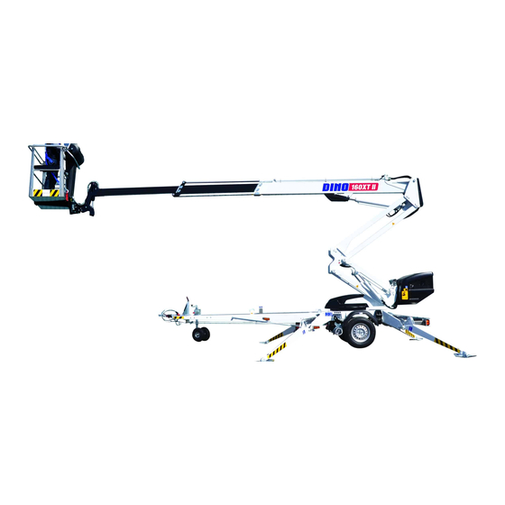
Dinolift 160XT II Operating Instructions Manual
Hide thumbs
Also See for 160XT II:
- Maintenance instructions manual (82 pages) ,
- Operating instructions manual (73 pages) ,
- Quick manual (2 pages)

Subscribe to Our Youtube Channel
Related Manuals for Dinolift 160XT II


Summary of Contents for Dinolift 160XT II
- Page 1 OPERATING INSTRUCTIONS 160XT II 180XT II 210XT II Manufacturer: Dealer: Raikkolantie 145 FI-32210 LOIMAA Tel. +358 20 1772 400 info@dinolift.com www.dinolift.com...
- Page 3 DINO XT II TRANSLATION OF ORIGINAL OPERATING INSTRUCTIONS Valid from serial number: 160XT II 17156 -> 180XT II 20001, 30002 -> 210XT II 3370 ->...
-
Page 4: Table Of Contents
DINO XT II TABLE OF CONTENTS TO THE OPERATOR ....................7 1.1. OVERVIEW OF THE UNIT .................. 8 1.2. INTENDED USE OF THE WORK PLATFORM ........... 8 TECHNICAL SPECIFICATION ..................9 2.1. DIMENSIONAL DRAWINGS ................10 2.1.1. 160 XT II ....................10 2.1.2. - Page 5 DINO XT II 5.2. INSTRUCTIONS FOR WORKING ..............39 5.2.1. Operating the lift from the chassis control centre LCB ......39 5.2.2. Operating the lift from the platform control centre UCB ......39 5.2.3. Special instructions for winter use ............42 5.2.4.
- Page 6 DINO XT II...
-
Page 7: To The Operator
Dinolift Oy is constantly developing its products. For this reason, the contents of this manual might not always be in full compliance with the most recent version of the product. Dinolift Oy reserves the right to modify the product without prior notice. Dinolift Oy assumes no liability for any problems caused by changed or missing data or mistakes in this manual. -
Page 8: Overview Of The Unit
DINO XT II 1.1. OVERVIEW OF THE UNIT This unit is a trailer mounted, towable aerial work platform. It is an aerial work platform, which complies with the EN280 type 1, where travelling is only allowed with the platform in transport configuration. For the operation the lift shall be supported by its hydraulic outriggers, extended so that the unit’s wheels lift off the ground. -
Page 9: Technical Specification
DINO XT II TECHNICAL SPECIFICATION 160XT II 180XT II 210XT II Max. working height 16,0 m 18,0 m 21,0 m Max. platform height 14,0 m 16,0 m 19,0 m Max. outreach 9,1 m 11,2 m 11,7 m Boom rotation continuous Platform rotation 180°... -
Page 10: Dimensional Drawings
DINO XT II 2.1. DIMENSIONAL DRAWINGS 2.1.1. 160 XT II... -
Page 11: 180 Xt Ii
DINO XT II 2.1.2. 180 XT II... -
Page 12: 210 Xt Ii
DINO XT II 2.1.3. 210 XT II... -
Page 13: Reach Diagram
DINO XT II 2.2. REACH DIAGRAM 2.2.1. 160 XT II 215 KG 475 LB DINO 160XT II... -
Page 14: 180 Xt Ii
DINO XT II 2.2.2. 180 XT II... -
Page 15: 210 Xt Ii
DINO XT II 2.2.3. 210 XT II 215 KG 475 LB 120 KG 265 LB 80 KG 175 LB... -
Page 16: Example Of Machine's Nameplate
DINO XT II 2.3. EXAMPLE OF MACHINE’S NAMEPLATE Every machine has a nameplate shown in the picture below. In the nameplate are marked the name and address of machine manufacturer, serial number of the machine and other relevant machine information. DINO Type Manufacturer... -
Page 17: Model Of Ec-Declaration Of Conformity
Following harmonized standards have been applied in designing the machine: SFS-EN 280:2013; SFS-EN 60204-1/A1; SFS-EN-ISO 12100 Person authorized to draw up the Technical File: Santtu Siivola Chief Engineer Dinolift Oy, Raikkolantie 145, 32210 Loimaa, FINLAND Loimaa 05.02.2015 ----------------------------------------- Antti Tuura... -
Page 18: Model Of Inspection Protocol For The Access Platform
DINO XT II 2.5. MODEL OF INSPECTION PROTOCOL FOR THE ACCESS PLATFORM TEST CERTIFICATE DATE: 16.9.2014 www.dinolift.com START-UP TESTS: Inspection place: Dinolift Oy Inspector's signature: 1074 BASIC KNOWLEDGE Manufacturer: Dinolift OY Place of manufacture: Finland Address: Raikkolantie 145 32210 LOIMAA... - Page 19 Raikkolantie 145 FIN-32210 LOIMAA, FINLAND Tel. +358 - 20 - 1772 400, Fax +358 - 2 - 7627 160, e-mail: info@dinolift.com Dino access platforms are subjected to an overload test and structural and functional inspection for the first time at the factory by the manufacturers authorized inspector. This is a model of a test certificate that is drawn up based on the inspection and delivered with the platform.
-
Page 20: Safety
DINO XT II SAFETY This part describes all relevant warnings and safety rules and instructions regarding transport, operation and maintenance of the access platform. DANGER Failure to obey the operation, maintenance or safety instructions in this manual will result in death or serious injury. Read and understand all safety rules, operating instructions and machine labels and obey them. - Page 21 DINO XT II Beware of fixed or moving obstacles in the terrain or near the lift while driving. Make sure that you have a clear view of the driving path. WORK AREA AND PREPARATION FOR LIFTING When working in busy areas the operating range of the lift must be clearly marked either by using warning lights or fencing.
- Page 22 DINO XT II The lift must not be used for transferring goods or persons between different floors or working levels. Stepping on or off the platform in motion is prohibited. When the boom is in its lowest positions, make sure it cannot clash during rotation with structures that do not turn with the boom.
-
Page 23: Safety Messages
DINO XT II 3.2. SAFETY MESSAGES The following safety alert symbols and safety signal words are used in this manual. Obey all safety instructions that follow these symbols, in order to avoid dangerous situations and personal injuries. This is a general safety alert symbol and it is used to alert you to a potential hazard. Obey all safety messages that follow this symbol. -
Page 24: Safety Devices
DINO XT II 3.3. SAFETY DEVICES 1. Support outriggers (Fig. A) The safety limit switch RK3 prevents the operation of the outriggers and the driving device when the boom is not resting on the transport support. The switch is located on the tow-bar at the transport support. - Page 25 DINO XT II RK7, RK8 RK4, RK5 RK11, RK12, RK13, RK14...
-
Page 26: Basic Structure And Functions
DINO XT II BASIC STRUCTURE AND FUNCTIONS The denominations of the machine’s essential parts and concepts, which are used later in these instructions, are described on this page. Platform control centre UCB 4.1. STRUCTURE Work platform Levelling cylinder (slave) Boom extension 3 Boom extension 2 Boom extension 1 Telescope cylinder... -
Page 27: Basic Functions
DINO XT II 4.2. BASIC FUNCTIONS Swing counter- clockwise Left Drive direction Right Swing clockwise Platform levelling Boom lift / lowering Articulated arms lifting / lowering Platform Boom rotation turning... -
Page 28: Operating Controls
DINO XT II 4.3. OPERATING CONTROLS 4.3.1. Operating controls in chassis control centre LCB Selector switch Lever switch for turning power off Q1.1 OFF- Lever switch for boom system LCB- control centre – outriggers – hydraulic Q1.2 Lever switch for telescope drive platform control centre Q1.3... -
Page 29: Operating Controls Of Drive System
DINO XT II 4.3.2. Operating controls of drive system 28A. Forward - backward 28A + 28L drive to the left 28A + 28R drive to the right 4.3.3. Operating controls of outriggers Front outrigger, right Front outrigger, left Rear outrigger, left Rear outrigger, right Position indicator of chassis... -
Page 30: Operating Controls In Platform Control Centre Ucb
DINO XT II 4.3.4. Operating controls in platform control centre UCB Close the cover of the chassis control centre before operating the controls on the platform. The cover must not be locked while the lift is in operation. Stop button for the engine Signal lights Start button for the engine Green –... - Page 31 DINO XT II 17. Control lever The functions to be controlled are selected using the ”dead-man-buttons” at the end of the joystick. Always press the button first, and only after that, turn the handle. The safety connection prevents the movements, if the handle is turned before depressing the button. Boom up Boom to the left Boom to the right...
-
Page 32: Setup With Two Control Levers (Option)
DINO XT II 4.3.5. Setup with two control levers (option) Platform contol centre UCB can be fitted with two control levers as an option. Right and left control lever (17 right/left) replace the normal control lever (17). Different functions are selected by turning the joystick in the desired direction of movement. Always press the button first, and only after that, turn the handle. -
Page 33: Automatic Levelling And Electric Control Of Driving Device - Dcb Centre (Option)
DINO XT II 4.4. AUTOMATIC LEVELLING AND ELECTRIC CONTROL OF DRIVING DEVICE – DCB CENTRE (OPTION) 45-48 Lever switch for driving, right (to the front-rear) Lever switch for automatic levelling Lever switch for driving, left (to the front-rear) Emergency stop Depressing the driving device rollers (option) Light for automatic levelling Lever switches for outriggers 1-4... -
Page 34: Operating Instructions
DINO XT II OPERATING INSTRUCTIONS 5.1. START-UP Before operating the lift, perform all daily maintenance measures listed in the maintenance schedule. The operator must do a worksite inspection and daily maintenance: • at the beginning of each workday • before operating the lift at a new worksite •... -
Page 35: Positioning The Lift
DINO XT II 5.1.2. Positioning the lift 1. make sure that the ground is even and hard enough to support the lift in a steady, level position. Soil material Density Max. ground pressure kg/cm² Gravel High density Medium density Loose Sand High density Medium density... -
Page 36: Connecting The Power Supply To The Lift
DINO XT II 5.1.3. Connecting the power supply to the lift A. POWERED BY AC-SUPPLY While the mains voltage is plugged in, the operating voltage of 12 VDC is supplied by a power source. • connect the mains cable to the power supply •... -
Page 37: Starting Up
DINO XT II 5.1.4. Starting up 1. Turn the selector switch (1) to position ”LCB centre”. 2. Start the engine by depressing the button 2 (green). The electric timer of the lift automatically disconnects the supply voltage (12 VDC) in about 1 hour after the electric motor or the combustion engine has been turned off. - Page 38 DINO XT II...
-
Page 39: Instructions For Working
DINO XT II 5.2. INSTRUCTIONS FOR WORKING Do all daily maintenance tasks and operational inspections stated in the maintenance manual before operating the lift. Failure to check the correct functioning of safety devices may cause serious injury or make the consequences of an accident worse. All malfunctions in safety devices must be repaired before operating the lift 5.2.1. - Page 40 DINO XT II • Moving the platform via the lever switches 30 and 36 requires that the dead-man- button 35 be depressed simultaneously. • The engine is switched off via the pushbutton 25. (See point “Operating controls in platform control centre UCB”) Do not add load (e.g.
- Page 41 DINO XT II Observe when lifting the platform the operating range of the platform depends on the load (see “Technical Data”) and • is monitored by the safety limit switches RK4 and RK5, which are located under the protecting cover The limit switches must not be adjusted or modified.
-
Page 42: Special Instructions For Winter Use
DINO XT II 5.2.3. Special instructions for winter use The lowest allowed operating temperature of the lift is -20 °C In cold conditions do the following special actions in addition to normal start-up procedure. 1. if the temperature is below zero, let the power unit run for a few minutes before starting the movements 2. -
Page 43: Transport
DINO XT II 5.3. TRANSPORT The lift can be moved by towing or with the platforms driving device. Moving the lift is only allowed in the transport position. No persons or other additional load is allowed on the platform while transport. 5.3.1. - Page 44 DINO XT II 4. Turn the selector switch (1) to position ”chassis control centre LCB”. 5. Start the electric motor (With combustion engine, start the engine and set the engine revolutions at 3/4 of the maximum speed. The running speed of the power unit affects the speed of driving. 6.
-
Page 45: Towing The Lift
DINO XT II Do not drive downhill with the driving device, if the inclination of the surface is more than 5 per cent, i.e., more than 1/20 (corresponding to a descent of 0.5 m over a distance of 10 m). If the gradient of the surface is greater than this, you may lose control of the device. - Page 46 DINO XT II While towing, in addition to the instructions in this manual, the user must also observe the road traffic legislation, regulations valid at the work site and towing instructions of the towing vehicle. Always ensure before towing: • transport position of the outriggers •...
-
Page 47: Lifting The Device
DINO XT II 5.4. LIFTING THE DEVICE The device can be lifted from the lugs shown in the picture. Lugs are placed symmetrically on both sides. Lifting lugs are also marked in the machine with instructional labels. During lifting the platform must be in transport position. Remove all loose material and other excess load from the platform before lifting. -
Page 48: In Case Of Emergency
DINO XT II 5.6. IN CASE OF EMERGENCY 5.6.1. When at risk of losing stability Reduced stability can be caused by a fault in the lift, the wind or other lateral force, collapse of the standing base or negligence in providing sufficient support. In most cases one sign of reduced stability is the inclination of the lift. -
Page 49: In Case The Power Supply Is Interrupted
DINO XT II 5.6.3. In case the power supply is interrupted (power unit / combustion engine) As a precaution against possible power failure, the lift is equipped with a battery operated emergency descent system. Lower the boom using the emergency descent system 1. -
Page 50: Fault Finding
DINO XT II FAULT FINDING FAULT REMEDY 1. Electric motor cannot be started by depressing the start button, although the selector switch 1 is in position LCB or UCB The emergency stop button has jammed in the lower position. Fuse F1 has blown. Replace the fuse (10A). - Page 51 DINO XT II FAULT REMEDY 6. Outriggers do not move Boom is not resting on the transport support. Drive the boom onto the transport support. The selector switch is in the wrong position. Turn the selector switch to position LCB. Drive the boom onto the transport support Limit switch on the boom support has not and check the operation of the limit switch...
- Page 52 DINO XT II...
- Page 53 DINO XT II NOTES...
-
Page 54: Servicing And Maintenance
DINO XT II SERVICING AND MAINTENANCE Maint. Schedule Person responsible Reference Operating Daily Operator instructions Maintenance 1 month / 100 hours* Competent person who is familiar with the lift instructions 6 months / 500 Maintenance Competent person who is familiar with the lift hours* instructions Annually / 1000... - Page 55 DINO XT II Maintenance item Axles and suspension Driving device Lights Hydraulic oil Hydraulic hoses, pipes and fittings Condition and attachment of battery, electrical devices and wiring Hydraulic pressure Condition of safety limit switches Operation of safety limit switches Operation of overload protection device Load holding and load regulation valves Platform levelling system Platform control devices...
-
Page 56: Inspections Required By Authorities
DINO XT II 7.1. INSPECTIONS REQUIRED BY AUTHORITIES Inspections must be performed in accordance with local, state or federal regulations, legislation, directives, standards. The manufacturer recommends following inspections, as required by local authorities in platforms country of origin. A pre-use inspection must be done before taking the platform to use for the first time and before first start-up after major repairs and alterations. -
Page 57: Lubrication Plan
DINO XT II 7.2. LUBRICATION PLAN... -
Page 58: Routine Maintenance During Operation
DINO XT II ROUTINE MAINTENANCE DURING OPERATION This chapter describes the service and maintenance operations that the operator of the platform is responsible for. Other maintenance operations require special training, tools and materials or specific measurements and adjustment values. They are separately described in maintenance instructions manual. -
Page 59: Daily Maintenance Tasks
DINO XT II 8.1. DAILY MAINTENANCE TASKS 8.1.1. Condition of chassis, boom and work platform Inspect visually the condition of access systems, work platform, platform gate and handrails. Check that the chassis and boom have no visible signs of structural damage. 8.1.2. -
Page 60: Check The Emergency Descent, Emergency Stop And Sound Signal
DINO XT II 8.1.7. Check the emergency descent, emergency stop and sound signal Test the correct operation of emergency stop, emergency descent system and the sound signal from the lower controls and platform controls. • lift the boom up approximately 1-2 meters and drive the telescope out 1-2 meters. While driving the movement, push down the emergency stop button. - Page 61 DINO XT II...
- Page 62 DINO XT II...
-
Page 63: Transfer Of Ownership
If you have purchaced a used DINO lift covered by this manual from somewhere other than the manufacturer, please use this form to provide your information to the manufacturer via e-mail to the address: info@dinolift.com The updated ownership information allowes you yo recieve information like safety bulletins or other campaigns concerning your lift. - Page 64 DINO XT II...
- Page 65 DINO XT II NOTES...
Need help?
Do you have a question about the 160XT II and is the answer not in the manual?
Questions and answers