Table of Contents
Advertisement
Quick Links
Advertisement
Table of Contents

Related Manuals for DFI EC300-CS


Summary of Contents for DFI EC300-CS
- Page 1 EC300-CS Edge AI Embedded System User’s Manual ©July 17, 2024 DFI Inc.
- Page 2 1. The changes or modifications not expressly approved by the party responsible for com- are the properties of the respective owners. pliance could void the user’s authority to operate the equipment. 2. Shielded interface cables must be used in order to comply with the emission limits. User's Manual | EC300-CS...
-
Page 3: Table Of Contents
LPC (J3) .........................29 SATA1 Power (CN38) ....................29 SATA0 Power (CN37) ....................30 Power Pin Define of DC 9-36V ..................30 Chapter 4 - BIOS Settings ......................31 Overview ..........................31 Main ............................32 Advanced ..........................32 RC ACPI Settings ......................33 CPU Configuration ......................33 User's Manual | EC300-CS... - Page 4 The manual is subject to change and update without notice, and may be based on editions that do not resemble your actual products. Please visit our website or contact our sales representa- • 1 EC300-CS System Unit tives for the latest editions. •...
- Page 5 Make sure the system is placed or mounted correctly and stably to prevent the chance of dropping or falling may cause damage. • The openings on the system shall not be blocked and shall be kept in distance from User's Manual | EC300-CS...
-
Page 6: Chapter 1 - Introduction
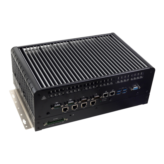
Power Button SIM Sockets COM1 Grounding 2.5” SSD Storage Driver Bay HDMI PoE3 Antenna Hole DP++ LAN2 PoE2 USB2.0 LAN1 Status LED (Orange) PoE1 USB3.0 HDD LED (Red) LAN Power (Red) Line-out PoE Power (Green) Antenna Hole User's Manual | EC300-CS... -
Page 7: Dimensions
AI Accelerated Support up to 150W GPU GPU module Scalability 3 x miniPCIe and 2 x M.2 slots Support 5G Communication Support M.2 B key 3042/3052 5G-NR module Wide-Temperature Up to -20°C~70°C operation without active fan User's Manual | EC300-CS... -
Page 8: Specifications
4 x RJ45 802.3af (15.4w) PoE connectors. Supporting PSE side. NOT support Wake on Lan Ethernet 2 x GbE (RJ-45) support Wake on Lan Serial 2 x High speed full RS-232/422/485 (DB-9) 2 x RS-232/422/485 (pin headers) User's Manual | EC300-CS... - Page 9 Test Axis : X, Y, Z axis Test Time : 30 mins (Each axis), total 90 mins MIL-STD-810G Method 514.6C-3, Category 4 Composite wheeled vehicle Table 514.6C-VI IP Rating IP40 Certification CE, FCC Class A, UKCA, RoHS User's Manual | EC300-CS...
-
Page 10: Power Consumption
Worse Case Load TAT(CPU,GPU load:100%)+Burn-In( I/O load:100%). 3D Mark Load 3Mark+Burn in( I/O load:100%) Select WOL enable & disable mode in BIOS menu, Power off the system. (No external devices attached) 5. Recode the power usage (in watts). User's Manual | EC300-CS... -
Page 11: Chapter 2 - Hardware Installations
2. Disconnect all power cords and cables. Turn over the machine to let the bottom side become the top. Step 1: Remove eight screws circled by red in each corner. The SSD part appears. Step 3: User's Manual | EC300-CS... - Page 12 Step 6: Step 4: cables first. If you want to change/remove/install other components, please remove the Step 5: first layer first. Remove the 4 screws in each corner circled by red. The main body appears. Step 7: User's Manual | EC300-CS...
-
Page 13: Installing An Mxm Card
To locate a MXM card socket, please follow the section and lift the Removing the Chassis Cover cover to open the system. Step 2: Remove the screws/standoffs marked in red circle on the main board. Remove all 10 standoffs User's Manual | EC300-CS... - Page 14 Chapter 2 HARDWARE INSTALLATION Step 4: Gently lift the main board and turn it to the other side. A MXM card socket is on the back side of the main board. MXM Card Socket User's Manual | EC300-CS...
- Page 15 Type Model CUDA Cores Power Support Operating Temperature P1000 -20°C to +70°C P2000 -20°C to +70°C T1000 -20°C to +70°C Quadro RTX3000 1920 -20°C to +55°C -20°C to +55°C RTX5000 3072 150W (external air flow needed) User's Manual | EC300-CS...
-
Page 16: Installing An Antenna
Chassis Wall There are antenna holes reserved on the front and the rear side of the system and covered by rubber plugs. Please remove the plug prior to installing an antenna. Module Connector Cable Antenna Connector Washer User's Manual | EC300-CS... -
Page 17: Inserting A Hdd/Sdd
Close the drive latch to lock the drive in place. Step 2: Pull the silver latch to unlock the door. Important: Excessive force may damage its mechanical parts. If the HDD/SSD is inserted backward into the slot, forcing the device may damage the slot. User's Manual | EC300-CS... -
Page 18: Installing The M.2 Module
Reset Button Header and a stand-off screw until CN37 the gap between the card and Power SYS_FAN Button the stand-off closes up. The 12V_DC1 card should be lying parallel to the board when it’s correctly mounted. User's Manual | EC300-CS... -
Page 19: Installing The So-Dimm Module
Inspect that SATA0(R2) SMBus Reset the clip sits in the notch. If not, please pull the Button Header CN37 clips outward, release and remove the card, and Power mount it again. Button SYS_FAN 12V_DC1 Step 3 User's Manual | EC300-CS... -
Page 20: Mounting Options
Locate the mount- ing holes on the bottom of the system as shown in the photo. Screw on the two brackets onto the system with six screws as illustrated below. Wall Mount Bracket Wall Mount Bracket User's Manual | EC300-CS... -
Page 21: Chapter 3 - System Settings
ESD protection by wearing an antistatic wrist strap and attaching it to a metal part of the system chassis. If a wrist strap is unavailable, establish and maintain contact with the system chassis throughout any procedures requiring ESD protection. User's Manual | EC300-CS... -
Page 22: Jumper Settings
CN37 CN37 Power Power Power Power SYS_FAN SYS_FAN SYS_FAN SYS_FAN Button Button Button Button 12V_DC1 12V_DC1 12V_DC1 12V_DC1 „ 1-2 On: 3V3 (default) „ 2-3 On: 3V3SB „ 1-2 On: 3V3SB (default) „ 2-3 On: 3V3 User's Manual | EC300-CS... -
Page 23: Dio Power (Isjp5)
CN37 Power Power Power Power SYS_FAN SYS_FAN SYS_FAN SYS_FAN Button Button Button Button 12V_DC1 12V_DC1 12V_DC1 12V_DC1 „ 1-2 On: 5VSB (default) „ 2-3 On: 5V „ 1-2 On: DIO PWR (default) „ 2-3 On: GND User's Manual | EC300-CS... -
Page 24: Di 0~3 Power (Isjp4)
CN37 Power Power Power Power SYS_FAN SYS_FAN SYS_FAN SYS_FAN Button Button Button Button 12V_DC1 12V_DC1 12V_DC1 12V_DC1 „ 1-2 On: DIO PWR (default) „ 2-3 On: GND „ 1-2 On: 3V3SB (default) „ 2-3 On: 3V3 User's Manual | EC300-CS... -
Page 25: Mini Pcie2 Power (Mpjp3)
USB2_1/2 CN38 CN38 USB3_1/2 USB3_1/2 12V_DC2 12V_DC2 SATA0(R2) SATA0(R2) SMBus SMBus Reset Reset Button Button Header Header CN37 CN37 Power Power SYS_FAN SYS_FAN Button Button 12V_DC1 12V_DC1 „ 1-2 On: 3V3SB (default) „ 2-3 On: 3V3 User's Manual | EC300-CS... -
Page 26: Pin Assignment
Power Power Button Button SYS_FAN SYS_FAN Button Button SYS_FAN SYS_FAN 12V_DC1 12V_DC1 12V_DC1 12V_DC1 Assignment Assignment Assignment Assignment MSIN4 X_MDCD3- MSIN3 X_MDCD4- MSOUT4 MDTR4- MSOUT3 MDTR3- MDSR4- MDSR3- MRTS3- MCTS3- MRTS4- MCTS4- X_MRI4- ---- X_MRI3- ---- User's Manual | EC300-CS... -
Page 27: Sata3 Power (Cn40)
SMBus SMBus Button Button Header Header Button Button Header Header CN37 CN37 CN37 CN37 Power Power Power Power Button Button SYS_FAN SYS_FAN Button Button SYS_FAN SYS_FAN 12V_DC1 12V_DC1 12V_DC1 12V_DC1 Assignment Assignment +12V_SATA2 +12V_SATA2 5V_SATA2 5V_SATA2 User's Manual | EC300-CS... -
Page 28: Smbus Header (J12)
Button Button Header Header CN37 CN37 Button Button Header Header CN37 CN37 Power Power Power Power SYS_FAN SYS_FAN Button Button Button Button SYS_FAN SYS_FAN 12V_DC1 12V_DC1 12V_DC1 12V_DC1 Function Function Function 3V3SB SMB_CLK_RESUME SMB_DATA_RESUME SMBALERT_PCH- TACH User's Manual | EC300-CS... -
Page 29: Lpc (J3)
Power Power CN37 CN37 SYS_FAN SYS_FAN Button Button Power Power 12V_DC1 12V_DC1 SYS_FAN SYS_FAN Button Button 12V_DC1 12V_DC1 1 1 1 Assignment Assignment LAD1 Assignment RST# LAD0 +12V_SATA1 FRAME# VCC3 LAD3 LAD2 N.C. 5V_SATA1 SERIRQ 5VSB User's Manual | EC300-CS... -
Page 30: Sata0 Power (Cn37)
SATA1(R3) SATA1(R3) USB2_1/2 USB2_1/2 CN38 CN38 USB3_1/2 USB3_1/2 12V_DC2 12V_DC2 SATA0(R2) SATA0(R2) SMBus SMBus Reset Reset Button Button Header Header CN37 CN37 Power Power Button Button SYS_FAN SYS_FAN 12V_DC1 12V_DC1 1 1 1 Assignment +12V_SATA1 5V_SATA1 User's Manual | EC300-CS... -
Page 31: Chapter 4 - Bios Settings
When “X” appears on the left of a particular field, it indicates that a submenu which contains additional options are available for that field. To display the submenu, move the highlight to that field and press <Enter>. User's Manual | EC300-CS... -
Page 32: Main
The time format is <hour>, <minute>, <second>. The time is based on the 24-hour military-time clock. For example, 1 p.m. is 13:00:00. Hour displays hours from 00 to 23. Minute displays min- utes from 00 to 59. Second displays seconds from 00 to 59. User's Manual | EC300-CS... -
Page 33: Rc Acpi Settings
The system enter soft-off state after power failure. Power-on signal input is required to power up the system. Last State The system returns to the last state right before power failure. Virtual Battery Enable or disable virtual battery. User's Manual | EC300-CS... -
Page 34: Power & Performance
Enable or disable CPU Power Management. It allows CPU to enter "C states" when it’s idle and ME Unconfig on RTC Clear nothing is executing. When disabled, ME will not be unconfigured on RTC Clear. Firmware Update Configuration Configure Management Engine Technology Parameters. User's Manual | EC300-CS... -
Page 35: Pch-Fw Configuration ► Amt Configuration
Secure Erase Configuration Menu Pending operation To clear the existing TPM encryption, select "TPM Clear" and restart the system. This field is OEM Flags Settings not available when "Security Device Support" is disabled. Configure OEM Flags. User's Manual | EC300-CS... -
Page 36: Nct6116D Super Io Configuration
Select WatchDog Timer Unit — Second or Minute. SuperIO WatchDog Timer Set SuperIO WatchDog Timer Timeout value. The range is from 0 (disabled) to 255. Serial Port Enable or disable serial port. Electrical Interface Mode Choose mode between RS232 / RS485 / RS422 User's Manual | EC300-CS... -
Page 37: Nct6116D Super Io Configuration Nct6116D Super Io Configuration Nct6116D Hw Monitor
This section displays the system’s health information, i.e. voltage readings, CPU and system temperatures, and fan speed readings Serial Port Enable or disable serial port. Electrical Interface Mode Choose mode between RS232 / RS485 / RS422 User's Manual | EC300-CS... -
Page 38: Nct6126D Hw Monitor ► Smart Fan Function
SYS Smart Fan/CPU Smart Fan Control = [Disabled] • Fix Fan Speed Count Set the fan speed, the value ranging from 1-100%, 100% being full speed. The fans will always operate at the specified speed regardless of gauged temperatures. User's Manual | EC300-CS... -
Page 39: Serial Port Console Redirection ► Console Redirection Settings
Chapter 4 BIOS SETTINGS Advanced Serial Port Console Redirection ► Console Redirection Settings Serial Port Console Redirection ► Console Redirection Settings User's Manual | EC300-CS... -
Page 40: Usb Configuration
Keep USB devices available only for EFI applications. Auto Disable Legacy support if no USB devices are connected. XHCI Hand-off Enable or disable XHCI Hand-off. USB Mass Storage Driver Support Enable or disable USB Mass Storage Driver Support. User's Manual | EC300-CS... -
Page 41: Csm Configuration
Controls the execution of UEFI and Legacy Network OpROM Storage Controls the execution of UEFI and Legacy Storage OpROM Video Controls the execution of UEFI and Legacy Video OpROM Other PCI devices Determines OpROM execution policy for devices otherthan Network, Storage, or Video. User's Manual | EC300-CS... -
Page 42: Network Stack Configuration
Set the wait time in seconds to press ESC key to abort the PXE boot. Use either +/- or numeric keys to set the value. Media detect count Set the number of times the presence of media will be checked. Use either +/- or numeric keys to set the value. User's Manual | EC300-CS... -
Page 43: Chipset
Select which of IGFX/PEG/PCI Graphics device to be the primary display. Internal Graphics Enable/Disable PCIE Resizable BAR Support If disable adjust EnableAbove4GBMmio option accordingly Internal Graphics Keep IGFX "Enabled" or "Disabled" based on the setup options, or select "Auto" for auto-detec- tion. User's Manual | EC300-CS... -
Page 44: Peg Port Configuration
PEG Port Configuration PEG Port Configuration ► PEG Port Feature Configuration Detect Non-Compliance Device Enable Root Port Detect Non-Compliance PCI Express Device in PEG Enable/Disable the Root Port Max Link Speed Configure PEG 0:1:0 Max Speed User's Manual | EC300-CS... -
Page 45: Pch-Io Configuration
Assign the maximum value of Top Of Lower Usable DRAM (TOLUD). Select to specify a fixed value, or select "Dynamic" so that the assignment would adjust TOLUD automatically based on largest MMIO length of installed graphic controller. User's Manual | EC300-CS... -
Page 46: Sata And Rst Configuration
This option allows you to create RAID or Intel Rapid Storage configuration along with Intel® Optane™ system acceleration on Serial ATA devices. Ports and Hot Plug Enable or disable the Serial ATA port and its hot plug function. User's Manual | EC300-CS... -
Page 47: Security
Secure Boot. Press Enter and a prompt will show up for you to confirm. Reset To Setup Mode Clear the database from the NVRAM, including all the keys and signatures installed in the Key Management menu. Press Enter and a prompt will show up for you to confirm. User's Manual | EC300-CS... -
Page 48: Boot
Select this option to save BIOS configuration settings to a USB flash device. ► Restore Setting from file This field will appear only when a USB flash device is detected. Select this field to restore set- ting from the USB flash device. User's Manual | EC300-CS... -
Page 49: Updating The Bios
MAC address should be burned or not. c. After updating unique MAC Address from manufacturing, NVM will be protected immediately after power cycle. Users cannot update NVM or MAC address. User's Manual | EC300-CS...
Need help?
Do you have a question about the EC300-CS and is the answer not in the manual?
Questions and answers