
Related Manuals for DFI BT9A3


Summary of Contents for DFI BT9A3
- Page 1 BT9A3 COM Express Mini Module User’s Manual A31140952 Chapter 1 Introduction www.dfi.com...
-
Page 2: Copyright
2. Shielded interface cables must be used in order to comply with the emission limits. COM Express Specification Reference PICMG ® COM Express Module Base Specification. http://www.picmg.org/ Chapter 1 Introduction www.dfi.com... -
Page 3: Table Of Contents
CPU Fan Connector..................13 COM Express Connector ................13 COM Express Connector Signal Discription ..........15 Cooling Option .................... 21 Installing BT9A3 onto a Carrier Board ..........21 Installing the COM Express Debug Card ..........23 Chapter 1 Introduction www.dfi.com... -
Page 4: About This Manual
To reduce the risk of electric shock: • Unplug the power cord before removing the system chassis cover for installation or servic- ing. After installation or servicing, cover the system chassis before plugging the power cord. Chapter 1 Introduction www.dfi.com... -
Page 5: About The Package
About the Package The package contains the following items. If any of these items are missing or damaged, please contact your dealer or sales representative for assistance. • One BT9A3 board • One QR (Quick Reference) • One Heat sink Optional Items •... -
Page 6: Chapter 1 - Introduction
• Supports I C interface • Supports SMBus interface Note: • Suppotrs 2 serial interfaces (TX/RX) *Optional and is not supported in standard model. Please contact your sales represen- • Supports 8-bit Digital I/O tative for more information. Chapter 1 Introduction www.dfi.com... -
Page 7: Features
USB 1.1 (12Mb/s). USB 3.0 reduces the time required for data transmission, reduces power consumption, and is backward compatible with USB 2.0. It is a marked improvement in device transfer speeds between your computer and a wide range of simultaneously accessible external Plug and Play peripherals. Chapter 1 Introduction www.dfi.com... -
Page 8: Chapter 2 - Concept
Chapter 2 - Concept COM Express Module Standards The figure below shows the dimensions of the different types of COM Express modules. BT9A3 is a COM Express Mini. The dimension is 84mm x 55mm. Common for all Form Factors Extended only... -
Page 9: Specification Comparison Table
Specification Comparison Table The table below shows the COM Express standard specifications and the corresponding specifications supported on the BT9A3 module. COM Express Module Base COM Express Module Base Specification Type 10 Specification Type 6 DFI BT9A3 DFI BT9A3 Connector... -
Page 10: Chapter 3 - Hardware Installation
MMC Bus eMMC SATA 2.0 2x (Optional) PCIe x1 PCIe x1 PCIe x1 PCIe x1 (Opt.) GLAN Intel ® GLAN SMSC I210 USB4604 PCIe x1 eMMC IT8528 Switch (optional) Flash B110 COM Express connector A110 Bottom View Chapter 1 Introduction www.dfi.com... -
Page 11: Mechanical Diagram
Bottom View Mechanical Diagram 6.00 BT9A3 Module BT9A3 Module with Heat Sink 20.00 85.00 55.00 51.00 51.00 Top View 4.00 4.00 0.00 Heatsink Module PCB Bottom View Standoff Side View of the Module with Heat Sink and Carrier Board 6.00 20.00... -
Page 12: System Memory
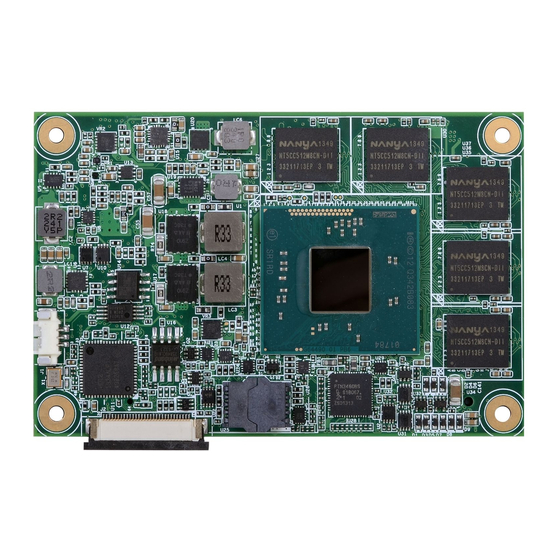
The system board is equipped with nine DDR3L memory chips onboard. • 2GB/4GB DDR3L ECC memory down • Supports DDR3L 1333MHz (-E45/-E27/-J00/-N30/-N07) Supports DDR3L 1066MHz (-E26/-E25/-E15) • Supports single channel memory interface DDR3L Bottom View DDR3L DDR3L Top View Chapter 1 Introduction www.dfi.com... -
Page 13: Connectors
Connectors COM Express Connector The COM Express connector is used to interface the BT9A3 COM Express board to a carrier CPU Fan Connector board. Connect the COM Express connector (located on the solder side of the board) to the COM Express connector on the carrier board. - Page 14 GND (FIXED) GND (FIXED) USB6- USB7- SPI_POWER USB6- DDI0_PAIR5+ USB7- SPI_POWER USB6- DDI0_PAIR5+ USB7- SPI_POWER DDI0_PAIR5+ USB6- USB7- SPI_POWER DDI0_PAIR5+ Chapter 1 Introduction USB6+ USB7+ SPI_MISO USB6+ USB6+ DDI0_PAIR5- USB7+ USB7+ SPI_MISO SPI_MISO USB6+ DDI0_PAIR5- DDI0_PAIR5- USB7+ SPI_MISO DDI0_PAIR5- www.dfi.com...
-
Page 15: Com Express Connector Signal Discription
PCI Express Differential Receive Pairs 2 Slot - Connect to PCIE Conn pin O PCIE AC coupled on Module PCI Express Differential Transmit Pairs 3 (NA for BT9A3) I PCIE AC coupled off Module PCI Express Differential Receive Pairs 3 (NA for BT9A3) - Page 16 PCI Express Differential Receive Pairs 2 Slot - Connect to PCIE Conn pin O PCIE AC coupled on Module PCI Express Differential Transmit Pairs 3 (NA for BT9A3) I PCIE AC coupled off Module PCI Express Differential Receive Pairs 3 (NA for BT9A3)
- Page 17 I PCIE AC coupled off Modul Additional receive signal differential pairs for the SuperSpeed USB data path.(NA for BT9A3) USB_SSRX1- Module USB client may detect the presence of a USB host. A high value(NA for BT9A3) USB_HOST_PRSNT I CMOS 3.3V Suspend/3.3V indicates that a host is present.
- Page 18 AC coupled off Modul Additional receive signal differential pairs for the SuperSpeed USB data path.(NA for BT9A3) Module USB client may detect the presence of a USB host. A high value(NA for BT9A3) indicates that a host is present. LVDS Signals Descriptions...
- Page 19 The module supplies a wide range of power from 4.75V to 20.0V. Standby power input: +5.0V nominal. If VCC5_SBY is used, all Chapter 1 Introduction available VCC_5V_SBY pins on the connector(s) shall be used. Only www.dfi.com used for standby and suspend functions. May be left unconnected if...
- Page 20 Ground - DC power and signal and AC signal return path. A80, A90, A100, A110, B1, Power All available GND connector pins shall be used and tied to Carrier B11, B21 ,B31, B41, B51, Board GND plane. B60, B70, B80, B90, B100, B110 Chapter 1 Introduction www.dfi.com...
-
Page 21: Cooling Option
These illustrations are mainly to guide you on Note: how to install BT9A3 onto the carrier board of your choice. The system board used in the following illustrations may not resemble the actual board. These illustrations are for reference only. - Page 22 3. While supporting the mounting screw at the bottom, from the top side of the board, fasten 6. Grasping BT9A3 by its edges, position it on the top of the carrier board with its mounting a bolt into the screw.
-
Page 23: Installing The Com Express Debug Card
Installing the COM Express Debug Card 8. Use the provided mounting screws to secure BT9A3 with heat sink to the carrier board and then connect the cooling fan’s cable to the fan connector on BT9A3. The photo below shows the locations of the long mounting screws. - Page 24 COM Express Type Display Signal Display COM Express Power/Reset/ Power Display Bolts Sleep/LID control 4. Use the provided bolts to fix the COMe-LINK2 debug card onto the carrier board. Cable COMe-DEBUG COMe-LINK2 Bolts COMe-LINK2 Carrier Board COMe-DEBUG Chapter 1 Introduction www.dfi.com...
- Page 25 6. Then, grasp the heat sink by its edges and position it down firmly on the top of the COM Express Mini module. Cable Carrier Board COM Express Mini Module COMe-LINK2 Side View of the Module, Debug Card and Carrier Board COMe-DEBUG Chapter 1 Introduction www.dfi.com...
-
Page 26: Chapter 4 - Bios Setup
When ““ appears on the left of a particular field, it indicates that a submenu which contains restart the system by pressing the <Ctrl> <Alt> and <Del> keys simultaneously. additional options are available for that field. To display the submenu, move the highlight to that field and press <Enter>. Chapter 1 Introduction www.dfi.com... -
Page 27: Ami Bios Setup Utility
Save & Exit Set the Date. Use Tab BIOS Information to switch between Date American Megatrends BIOS Vendor elements. BT9A3 0.11 x64 Project Version Aptio Setup Utility - Copyright (C) 2013 American Megatrends, Inc. 08/29/2014 11:54:41 Build Date and Time Main Advanced... - Page 28 [Enabled] (Sec). WatchDog1 Timer Select Screen → ←: Select Item ↑↓: Enter: Select +/ -: Change Opt. General Help Previous Values Optimized Defaults Save & Reset ESC: Exit Version 2.16.1242. Copyright (C) 2013 American Megatrends, Inc. Chapter 1 Introduction www.dfi.com...
- Page 29 This field is used to enable or disable the Serial ATA port 0 and 1. Intel Virtualization Technology When this field is set to enabled, the VMM can utilize the additional hardware capabili- ties provided by Vanderpool Technology. Chapter 1 Introduction www.dfi.com...
- Page 30 PXE boot wait time Select Screen → ←: Select Item ↑↓: Enter: Select +/ -: Change Opt. General Help Previous Values Optimized Defaults Save & Reset ESC: Exit Version 2.16.1242. Copyright (C) 2013 American Megatrends, Inc. Chapter 1 Introduction www.dfi.com...
- Page 31 This field controls the execution of UEFI and Legacy Video OpROM. USB Mass Storage Driver Support Other PCI devices Enable or disable the support of the USB Mass Storage Driver. This field determines OpROM execution policy for devices other than network, storage or video. Chapter 1 Introduction www.dfi.com...
- Page 32 Save & Reset ports ESC: Exit USB type in table 2 below. Version 2.16.1242. Copyright (C) 2013 American Megatrends, Inc. Table 2. The Type of USB Ports Model Name BT9A3 USB 3.0 Native USB 0 Native USB 1 Native USB 2...
- Page 33 This field indicates the link status of the network device. Enables the server to be powered on using an in-band magic packet. Virtual MAC Address This field indicates programmatically assignable MAC address for the network port. Chapter 1 Introduction www.dfi.com...
-
Page 34: Chipset
Previous Values General Help Optimized Defaults Previous Values Save & Reset Optimized Defaults ESC: Exit Save & Reset ESC: Exit Version 2.16.1242. Copyright (C) 2013 American Megatrends, Inc. Version 2.16.1242. Copyright (C) 2013 American Megatrends, Inc. Chapter 1 Introduction www.dfi.com... - Page 35 VGA modes will be supported only on primary display. Secondary IGFX Boot Display Select the secondary display device: DDI-0 or DDI-1. DDI-0 is the default setting. Chapter 1 Introduction www.dfi.com...
- Page 36 General Help Version 2.16.1242. Copyright (C) 2013 American Megatrends, Inc. Previous Values Optimized Defaults Save & Reset ESC: Exit Version 2.16.1242. Copyright (C) 2013 American Megatrends, Inc. LVDS Support Enable or disable the onboard LVDS function. Chapter 1 Introduction www.dfi.com...
- Page 37 AC power failure occurs, the system will power-on when power returns. Enable or disable the internal HDMI codec for Azalia. Intel(R) I210 Controller DP/HDMI Port C Enable the Intel(R) I210 ethernet controller. Enable or disable the DP/HDMI Port C. Chapter 1 Introduction www.dfi.com...
-
Page 38: Security
Enable or disable the PCI Express port in the chipset. Set the administrator password. Speed User Password Select the speed for the PCI Express devices. The options are Auto, Gen1 or Gen2. Set the user password. Chapter 1 Introduction www.dfi.com... -
Page 39: Boot
Set the system boot order. <Enter>. A dialog box will appear. Select Yes to restore the default values of all the Hard Drive BBS Priorities setup options. Set the order of the legacy devices in this group. Chapter 1 Introduction www.dfi.com... -
Page 40: Updating The Bios
MAC address should be burned Writing BootBlock ....done or not. Verifying BootBlock ....done C:\AFU\AFUDOS> After finishing BIOS update, please turn off the AC power. Wait about 10 seconds and then turn on the AC power again. Chapter 1 Introduction www.dfi.com... -
Page 41: Chapter 5 - Supported Software
Install drivers, utilities and software applications that are required to facilitate and enhance the performance of the system board. You may acquire the software from your sales representa- tives, from an optional DVD included in the shipment, or from the website download page at https://www.dfi.com/DownloadCenter. For Windows 8.x Note: This step can be ignored if the applications are standalone files�... - Page 42 Next. 2. Read the license agreement then click Yes. 5. Click “Yes, I want to restart this computer now” then click Finish. Restarting the system will allow the new software installation to take effect. Chapter 1 Introduction www.dfi.com...
- Page 43 We recommend that you skip this process by disabling this function then click Next. 2. Read the license agreement then click Yes. 5. Click “Yes, I want to restart this computer now” then click Finish. Restarting the system will allow the new software installation to take effect. Chapter 1 Introduction www.dfi.com...
- Page 44 1. Setup is ready to install the driver. Click Next. 5. After completing installa- tion, click Finish. 2. Click “I accept the terms in the license agreement” then click “Next”. 3. Select the program featuers you want installed then click Next. Chapter 1 Introduction www.dfi.com...
- Page 45 “Next.” 2. The update is installed 2. The step shows the now. components which will be installed. Then, Click Next. 3. Click “Restart Now“ to restart your computer when the installation is complete. Chapter 1 Introduction www.dfi.com...
- Page 46 4. Click “Finish“ when the installation is complete. 3. Click “Yes, I want to restart my computer now” then click Finish. Restarting the system will allow the new software installation to take effect. Chapter 1 Introduction www.dfi.com...
- Page 47 To install the driver, click “Intel Sideband Fabric Device (MBI) Driver” on the main menu. 1. The setup program will be installed. Click “Next“ to continue. 4. Click “Finish“ to restart the computer when the setup is completely installed. 2. Click “Yes“ to accept the License Agreement. Chapter 1 Introduction www.dfi.com...
- Page 48 Next � DFI Utility provides information about the board, HW Health, Watchdog, DIO, and Backlight. To access the utility, click “DFI Utility” on the main menu. Note: If you are using Windows 7, you need to access the operating system as an administrator to be able to install the utility.
- Page 49 The DFI Utility icon will appear on the desktop. Double-click the icon to open the utility. Information WatchDog HW Health Chapter 1 Introduction www.dfi.com...
- Page 50 Intel USB 3.0 Drivers (For Windows 7 Only) To install the driver, click “Intel USB 3.0 Driver” on the main menu. 1. Setup is ready to install the driver. Click Next. Backlight 2� Read the license agreement then click Yes� Chapter 1 Introduction www.dfi.com...
- Page 51 Change Destination Folder to select another folder. 4. Setup is currently installing the driver. After installation has com- pleted, click Next. 2. Click Install to begin installation. 5. After completing installation, click Finish. 3. Click Finish to exit installation. Chapter 1 Introduction www.dfi.com...
-
Page 52: Chapter 6 - Gpio Programming Guide
GPIO Output Process EC_DIO_Write_Output(unsigned char udata) //Pin4-7 Output Mode udata <<= 4; udata |= 0x01; Write_EC_Data(0xBB, udata); return 0; EC_DIO_Read_Output() BYTE Data; //Pin4-7 Output Mode Write_EC_Data(0xBB, 0x02); Delay; Data = Get_EC_Data(0xBB); Data >>= 4; Return Data ; Chapter 1 Introduction www.dfi.com... -
Page 53: Appendix A - Watchdog Sample Code
//-------------------------------------------------------------- void WriteEC(char EC_Addr, int data) //-------------------------------------------------------------- //Select EC Write Type void SetWDTime(int count_H,int count_L) outportb(EC_EnablePort,0x81); delay(5); //Set Count outportb(EC_DataPort,EC_Addr); WriteEC(0xB5,count_H); //High Byte delay(5); WriteEC(0xB6,count_L); //Low Byte outportb(EC_DataPort,data); //Enable Watch Dog Timer delay(5); WriteEC(0xB4,0x01); //-------------------------------------------------------------- //-------------------------------------------------------------- Chapter 1 Introduction www.dfi.com... -
Page 54: Appendix B - System Error Message
0xA3 IDE Enable 0xB6 Clean-up of NVRAM 0xAE Legacy Boot event 0xB7 Configuration Reset (reset of NVRAM settings) 0xB4 USB hot plug DXE Error Codes Chapter 1 Introduction www.dfi.com 0xB6 Clean-up of NVRAM 0xD6 No Console Output Devices are found... - Page 55 No Console Output Devices are found DXE Error Codes DXE Error Codes 0xD7 No Console Input Devices are found 0xD8 0xD6 Invalid password No Console Output Devices are found 0xD7 No Console Input Devices are found 0xD8 Invalid password Chapter 1 Introduction www.dfi.com...
-
Page 56: Appendix C - Troubleshooting
AC outlet. If necessary, try another outlet. 3. Check that the video input cable is properly attached to the monitor and the system’s display adapter. 4. Adjust the brightness of the display by turning the monitor’s brightness control knob � Chapter 1 Introduction www.dfi.com... - Page 57 Nothing happens when a key on the keyboard was pressed. 1. Make sure the keyboard is properly connected. 2. Make sure there are no objects resting on the keyboard and that no keys are pressed dur- ing the booting process. Chapter 1 Introduction www.dfi.com...
Need help?
Do you have a question about the BT9A3 and is the answer not in the manual?
Questions and answers